EP0638273B1 - Küchengerät mit einer Deckelverriegelungsvorrichtung mit Zentrifugalelement - Google Patents
Küchengerät mit einer Deckelverriegelungsvorrichtung mit Zentrifugalelement Download PDFInfo
- Publication number
- EP0638273B1 EP0638273B1 EP94202204A EP94202204A EP0638273B1 EP 0638273 B1 EP0638273 B1 EP 0638273B1 EP 94202204 A EP94202204 A EP 94202204A EP 94202204 A EP94202204 A EP 94202204A EP 0638273 B1 EP0638273 B1 EP 0638273B1
- Authority
- EP
- European Patent Office
- Prior art keywords
- shaft
- lid
- kitchen machine
- centrifugal
- electric motor
- Prior art date
- Legal status (The legal status is an assumption and is not a legal conclusion. Google has not performed a legal analysis and makes no representation as to the accuracy of the status listed.)
- Expired - Lifetime
Links
- 230000008878 coupling Effects 0.000 claims description 17
- 238000010168 coupling process Methods 0.000 claims description 17
- 238000005859 coupling reaction Methods 0.000 claims description 17
- 230000000284 resting effect Effects 0.000 claims description 5
- 230000005484 gravity Effects 0.000 description 8
- 230000005540 biological transmission Effects 0.000 description 5
- 229920003002 synthetic resin Polymers 0.000 description 5
- 239000000057 synthetic resin Substances 0.000 description 5
- 239000002184 metal Substances 0.000 description 4
- 238000006073 displacement reaction Methods 0.000 description 3
- 238000010276 construction Methods 0.000 description 2
- 230000001419 dependent effect Effects 0.000 description 2
- 230000006378 damage Effects 0.000 description 1
- 239000011521 glass Substances 0.000 description 1
- 229920003217 poly(methylsilsesquioxane) Polymers 0.000 description 1
Images


Classifications
-
- A—HUMAN NECESSITIES
- A47—FURNITURE; DOMESTIC ARTICLES OR APPLIANCES; COFFEE MILLS; SPICE MILLS; SUCTION CLEANERS IN GENERAL
- A47J—KITCHEN EQUIPMENT; COFFEE MILLS; SPICE MILLS; APPARATUS FOR MAKING BEVERAGES
- A47J43/00—Implements for preparing or holding food, not provided for in other groups of this subclass
- A47J43/04—Machines for domestic use not covered elsewhere, e.g. for grinding, mixing, stirring, kneading, emulsifying, whipping or beating foodstuffs, e.g. power-driven
- A47J43/046—Machines for domestic use not covered elsewhere, e.g. for grinding, mixing, stirring, kneading, emulsifying, whipping or beating foodstuffs, e.g. power-driven with tools driven from the bottom side
-
- A—HUMAN NECESSITIES
- A47—FURNITURE; DOMESTIC ARTICLES OR APPLIANCES; COFFEE MILLS; SPICE MILLS; SUCTION CLEANERS IN GENERAL
- A47J—KITCHEN EQUIPMENT; COFFEE MILLS; SPICE MILLS; APPARATUS FOR MAKING BEVERAGES
- A47J43/00—Implements for preparing or holding food, not provided for in other groups of this subclass
- A47J43/04—Machines for domestic use not covered elsewhere, e.g. for grinding, mixing, stirring, kneading, emulsifying, whipping or beating foodstuffs, e.g. power-driven
- A47J43/07—Parts or details, e.g. mixing tools, whipping tools
- A47J43/075—Safety devices
- A47J43/0761—Safety devices for machines with tools driven from the lower side
- A47J43/0772—Safety devices for machines with tools driven from the lower side activated by the proper positioning of the cover
Definitions
- a special embodiment of a kitchen machine according to the invention is characterized in that the drivable shaft to which the centrifugal member is coupled is a motor shaft of the electric motor. Since the electric motor usually has a higher speed than the tool, the centrifugal member coupled to the motor shaft experiences a comparatively great centrifugal force, so that the operation of the locking device is very effective.
- the slide which cooperates with the safety member, is forced up along the drivable shaft by the ball during this.
- the ball After the electric motor has been switched off, the ball initially still rests against the stop during the run-out of the electric motor. The ball does not return to the drivable shaft under the influence of gravity until the moment the drivable shaft is substantially stationary, whereupon the slide resting on the ball slides down under the influence of gravity and the lid is released by the safety member.
- a special embodiment of a kitchen machine according to the invention is characterized in that the angle of inclination of the guides is substantially 30°.
- the use of the angle of inclination of substantially 30° achieves that the ball does not return to the first position after switching-off of the electric motor until the moment the drivable shaft is substantially stationary, while at the same time a strong locking force and a sufficient displacement of the slide can be achieved.
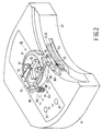
- a coupling bush 19 is journalled in the vertical rim 15 of the base 3.
- the coupling bush 19 is drivable by an electric motor 21 which is arranged in the motor housing 5, which has a motor shaft 23 arranged vertically, and which is coupled to the coupling bush 19 via a transmission 25 present in the base 3 such as, for example, a usual belt or gear transmission.
- the electric motor 21, the motor shaft 23 and the transmission 25 are depicted diagrammatically only in Fig. 1.
- a tool 27 can be placed in the bowl 9, such as, for example, a cutting tool shown in Fig. 1.
- Fig. 1 further shows that the bowl 9 is provided with a spout 49, while the lid 33 is provided with a lip 51 which covers the spout 49 when the lid 33 is locked to the bowl 9 by means of the bayonet closure 39, 41.
- the lip 51 has a vertical rim 53.
- Fig. 2 shows an upper portion of the motor housing 5 in which the slotted recess 55 is present.
- Fig. 2 further shows the lip 51 of the lid 33 with a broken line in a position in which the bowl 9 is locked to the base 3 by means of the bayonet closure 13, 17 and the lid 33 is locked to the bowl 9 by means of the bayonet closure 39,41.
- the vertical rim 53 of the lip 51 activates an electric switch 59 which is fastened in the motor housing 5 near the slotted recess 55 and which forms part of an electric circuit, not shown in Fig. 2 and known per se , for the supply of the electric motor 21.
- a number of electronic contact switches 61 for operating the electric motor 21 form part of the electric circuit.
- the electric circuit is so designed that the electric motor 21 can be switched on with the switches 61 exclusively when the electric switch 59 has been activated, i.e. when the bowl 9 and the lid 33 have been positioned correctly. It is prevented thereby that a user of the kitchen machine can injure himself with the rotating coupling bush 19 when the bowl 9 has not been placed, or with the tool 27 rotating in the bowl 9 when the lid 33 has not been placed on the bowl 9.
- Fig. 2 further shows a locking device 63 for locking the lid 33 during rotation of the tool 27.
- the locking device 63 is also arranged in the upper portion of the motor housing 5 and is provided with a centrifugal member 65 which is coupled to the vertically positioned motor shaft 23 of the electric motor 21.
- the centrifugal member 65 depicted in detail in Figs. 3 and 4 comprises a disc-shaped metal base 67 which has been screwed onto an end 69 of the motor shaft 23 and which extends transversely to the motor shaft 23.
- Three support blocks 71 are present on the disc-shaped base 67, each extending in a radial direction relative to the motor shaft 23, which three radial directions enclose angles of 120° with one another.
- the support blocks 71 each have an upper surface 73 which rises from the motor shaft 23 in the radial direction, the upper surface 73 enclosing a positive angle of inclination ⁇ of approximately 30° with the disc-shaped base 67.
- a metal ball 83 is present in each of the chambers 77 of the slide 75.
- the balls 85 rest on the upper surfaces 73 of the support blocks 71, while the slide 75 rests on the three balls 85 with the upper walls 87 of the chambers 77.
- the centrifugal member 65 is in a first position depicted in Fig. 5a, in which the balls 85 rest against the side walls 89 of the chambers 77 facing the motor shaft 23 under the influence of gravity, and the slide 75 is in a bottom position.
- the locking device 63 further comprises an elongate safety member 105 which extends in a direction transverse to the motor shaft 23 and to the coupling shaft 95 and which is guided with sliding possibility in said direction in the upper portion of the motor housing 5.
- the safety member 105 has a slot 107 which extends parallel to the motor shaft 23 and is in engagement with the pin 103 of the side arm 99.
- the safety member 105 comprises a detent 109 for cooperating with the vertical rim 53 of the lip 51 of the lid 33.
- the centrifugal member 65 Since the centrifugal member 65 is directly coupled to the high-speed motor shaft 23, the action of the locking device 63 is very effective. The speed with which the tool 27 rotates is considerably lower than the speed of the motor shaft 23 owing to the use of the transmission 25. Since the centrifugal member 65 does not return from the second position into the first position until at a comparatively low speed of the motor shaft 23, the lid 33 is only released when the speed of the tool 27 is substantially zero. In addition, the centrifugal force acting on the balls 85 of the centrifugal member 65 is great owing to the comparatively high speed of the motor shaft 23, so that a strong locking force is applied to the detent 109.
- the centrifugal member 65 is of a particularly simple construction.
- the disc-shaped base 67 and the support blocks 71 are manufactured from one piece of metal, while the slide 75 and the chambers 77 are made from one piece of synthetic resin.
- the balls 85 are laid in the chambers 77 and the base 67 is subsequently passed over the lips 79, whereby the slide 75 is locked relative to the base 67 because the rims 83 of the lips 79 hook behind the slots 81 of the base 67.
- the centrifugal member 65 is provided with three balls 85 guided along three support blocks 71 which enclose three mutual angles of substantially 120°, a regular distribution of the centrifugal forces around the motor shaft 23 is provided, so that the rotation of the centrifugal member 65 is substantially vibration-free.
- the three balls 85 exert a strong locking force on the detent 109.
- the effectivity of the locking device 63 is determined inter alia by the value of the angle of inclination ⁇ .
- the critical speed of the motor shaft 23 at which the balls 85 roll from the first into the second or from the second into the first position is very low, but the displacement of the slide 75 and the locking force on the detent 109 are only small.
- the angle of inclination ⁇ is comparatively great, a greater displacement of the slide 75 and a greater locking force on the detent 109 are indeed achieved, but the said critical speed is higher.
- the use of an angle of inclination ⁇ of approximately 30° leads to an optimum combination of critical speed and locking force.
- the lid 33 in that case is not released during the run-out of the tool 27 until the moment the tool 27 is substantially stationary, while the centrifugal member 65 exerts a force of approximately 20 kg on the pivot arm 93 at a speed of the motor shaft 23 of approximately 10000 rpm.
- the locking device 63 comprises only two movable parts besides the centrifugal member 65, i.e. the coupling shaft 95 which is manufactured integrally with the pivot arm 93 and the side arm 99, and the safety member 105 which is also manufactured integrally with the detent 109 and the slot 107.
- the locking device 63 can accordingly be assembled in a simple manner. Owing to the small number of components, moreover, the friction between the components is small, so that the operation of the locking device, part of which takes place exclusively under the influence of gravity, is reliable. The friction between the pivot arm 93 and the slide 75 is negligibly small owing to the use of the support ball 97.
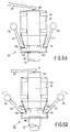
- centrifugal member 111 comprises a hollow shaft 113 which has been screwed onto the end 69 of the vertical motor shaft 23.
- the centrifugal member 111 further comprises two centrifugal weights 115 which are arranged diagonally opposite one another and are each fastened on an angled arm 117 which is pivotable relative to the hollow shaft 113 about a horizontal pivot 119.
- a further shaft 121 can slide in axial direction inside the hollow shaft 113.
- the further shaft 121 rests on the ends 123 of the angled arms 117 remote from the centrifugal weights 115.
- the pivot arm 93 mentioned above rests on a support ball 125 fastened on the further shaft 121.
- the centrifugal weights 115 When the motor shaft 23 is stationary, the centrifugal weights 115 are in a first position near the hollow shaft 113, as shown in Fig. 6a, under the influence of the weight of the further shaft 121 which rests on the angled arms 117 and of the pivot arm 93.
- the centrifugal weights 115 experience a centrifugal force owing to which the centrifugal weights 115 are displaced from the first position into the second position shown in Fig. 6b.
- the further shaft 121 and the pivot arm 93 are moved in vertical direction by the ends 123 of the angled arms 117, so that the safety member 105 (not shown in Figs. 6a and 6b) coupled to the pivot arm 93 is operated.
- a different number of balls 85 for example two or four, may alternatively be used in the centrifugal member 65, and that the angle of inclination ⁇ in the centrifugal member 65 may have a value other than 30°. It is further noted that the locking device 63 cooperating with the centrifugal member 65 may comprise an alternative type of safety member.
- the locking device 63 described above with the centrifugal member 65 operates independently of the means for operating the electric motor 21, so that the locking device 63 is eminently suitable for the use in a kitchen machine provided with electronic contact switches 61 for operating the electric motor 21.
- the locking device according to the invention may also be used in a kitchen machine provided with a mechanical switching button for operating the electric motor such as, for example, the kitchen machine disclosed in the European Patent 0 158 032 mentioned in the preamble.
Landscapes
- Engineering & Computer Science (AREA)
- Mechanical Engineering (AREA)
- Food Science & Technology (AREA)
- Food-Manufacturing Devices (AREA)
- Centrifugal Separators (AREA)
- Disintegrating Or Milling (AREA)
- Formation And Processing Of Food Products (AREA)
Claims (7)
- Küchenmaschine mit einem Gehäuse (1) und einer auf das Gehäuse (1) stellbaren Schüssel (9), die mittels eines Deckels (33) abschließbar ist, wobei in die Schüssel (9) ein drehbares Werkzeug (27) eingeführt werden kann, das mittels eines in dem Gehäuse (1) vorgesehenen Elektromotors (21) antreibbar während die Küchenmaschine mit einer Verriegelungsvorrichtung (63) versehen ist zum Verriegeln des Deckels im Betrieb des Werkzeugs (63), dadurch gekennzeichnet, daß die Verriegelungsvorrichtung (63) mit einem Zentrifugalelement (65) versehen ist, das mit einer von dem Elektromotor (21) antreibbaren Achse (23) drehbar gekuppelt ist und unter dem Einfluß einer Drehung der antreibbaren Achse (23) aus einer ersten in eine zweite Lage verlagerbar ist, sowie mit einem Sicherheitselement (105), das mit dem Deckel (33) und dem Zentrifugalelement (65) zusammenarbeitet, wobei das Sicherheitselement in der ersten Lage des Zentrifugalelementes (65) den Deckel (33) freigibt und in der zweiten lage des Zentrifugalelementes (65) den Deckel (33) verriegelt.
- Küchenmaschine nach Anspruch 1, dadurch gekennzeichnet, daß die antreibbare Achse (23), mit der das Zentrifugalelement (65) gekuppelt ist, eine Motorwelle des Elektromotors (21) ist.
- Küchenmaschine nach Anspruch 1 oder 2, dadurch gekennzeichnet, daß die antreibbare Achse (23) sich in verikaler Richtung erstreckt, während das Zentrifugalelement (65) mit einer Kugel (85) versehen ist, die mittels einer an der antreibbaren Achse (23) vorgesehenen und sich mit einem positiven Neigungswinkel schief an der antreibbaren Achse (23) erstreckenden Führung geführt wird, sowie mit einem Schieber (75), der mit dem Sicherheitselement (105) zusammenarbeitet, das auf der Kugel (85) ruht und parallel zu der antreibbaren Achse verlagerbar ist.
- Küchenmaschine nach Anspruch 3, dadurch gekennzeichnet, daß das Zentriifugalelement drei Kugeln (85) aufweist, die je in einer einzelnen Führung (73) geführt werden, wobei die Führungen zueinander einen Winkel von etwa 120° einschließen.
- Küchenmaschine nach Anspruch 3 oder 4, dadurch gekennzeichnet, daß der neigungswinkel der Führungen (73) nahezu 30° beträgt.
- Küchenmaschine nach Anspruch 3, 4 oder 5, dadurch gekennzeichnet, daß die Verriegelungsvorrichtung (63) mit einem Kipparm (93) versehen ist, der in der Nähe eines der Enden an einer Kupplunsgachse (95) befestigt ist, die sich quer zu der antreibbaren Achse (23) erstreckt und in dem Gehäuse (1) drehbar gelagert ist und in der Nähe des anderen Endes auf dem Schieber (75) ruht, während das Sicherheitselement (105) in einer Richtung quer zu der Antriebsachse (23) und quer zu der Kupplungsachse (95) verlagerbar ist und mit einem sich parallel zu der antreibbaren Achse (23) erstreckenden Schlitz (107) versehen ist, der mit einem auf einem Querarm (99) der Kupplungsachse (95) befestigten Stift (103) im Eingriff ist.
- Küchenmaschine nach Anspruch 6, dadurch gekennzeichnet, daß der Kipparm (93) auf einer Unterstützungskugel (97) des Schiebers ruht.
Applications Claiming Priority (2)
| Application Number | Priority Date | Filing Date | Title |
|---|---|---|---|
| BE9300811 | 1993-08-04 | ||
| BE9300811A BE1007431A3 (nl) | 1993-08-04 | 1993-08-04 | Keukenmachine voorzien van een dekselblokkering met een centrifugaal orgaan. |
Publications (2)
| Publication Number | Publication Date |
|---|---|
| EP0638273A1 EP0638273A1 (de) | 1995-02-15 |
| EP0638273B1 true EP0638273B1 (de) | 1998-05-20 |
Family
ID=3887239
Family Applications (1)
| Application Number | Title | Priority Date | Filing Date |
|---|---|---|---|
| EP94202204A Expired - Lifetime EP0638273B1 (de) | 1993-08-04 | 1994-07-28 | Küchengerät mit einer Deckelverriegelungsvorrichtung mit Zentrifugalelement |
Country Status (7)
| Country | Link |
|---|---|
| US (1) | US5486050A (de) |
| EP (1) | EP0638273B1 (de) |
| JP (1) | JPH0759671A (de) |
| AT (1) | ATE166212T1 (de) |
| BE (1) | BE1007431A3 (de) |
| BR (1) | BR9403146A (de) |
| DE (1) | DE69410365T2 (de) |
Cited By (2)
| Publication number | Priority date | Publication date | Assignee | Title |
|---|---|---|---|---|
| US6609821B2 (en) | 2001-04-13 | 2003-08-26 | Sunbeam Products, Inc. | Blender base with food processor capabilities |
| CN102805571A (zh) * | 2011-05-31 | 2012-12-05 | 德国福维克控股公司 | 用于释放烹调容器盖的方法以及带有煲煮容器的厨房设备 |
Families Citing this family (20)
| Publication number | Priority date | Publication date | Assignee | Title |
|---|---|---|---|---|
| US5833151A (en) * | 1996-06-29 | 1998-11-10 | Doak; Ron | Glass container hammer mill |
| AUPO908797A0 (en) | 1997-09-10 | 1997-10-02 | Lawson, Anthony Charles | Improved food mixer |
| US5921485A (en) * | 1998-04-10 | 1999-07-13 | Hp Intellectual Corp. | Food processor |
| DE19912750A1 (de) * | 1999-03-22 | 2000-09-28 | Braun Gmbh | Sicherheitseinrichtung für einen Bechermixer |
| GB9918356D0 (en) * | 1999-08-05 | 1999-10-06 | Duralit Limited | Electric blender |
| JP2004507303A (ja) * | 2000-08-31 | 2004-03-11 | コーニンクレッカ フィリップス エレクトロニクス エヌ ヴィ | 脱着可能なコンテナと保護手段とを備えたキッチン機器 |
| ATE392170T1 (de) * | 2001-06-29 | 2008-05-15 | Vorwerk Co Interholding | Küchenmaschine |
| US6554466B1 (en) * | 2002-02-22 | 2003-04-29 | Ming Tsung Lee | Blender with safety device |
| DE102013012192A1 (de) | 2012-08-16 | 2014-03-13 | Vorwerk & Co. Interholding Gmbh | Elektrisch betriebene Küchenmaschine |
| US9468339B2 (en) | 2013-03-15 | 2016-10-18 | Whirlpool Corporation | Low profile side drive blending appliance |
| US9555384B2 (en) | 2013-10-25 | 2017-01-31 | Whirlpool Corporation | Blender assembly |
| US9815037B2 (en) | 2013-10-25 | 2017-11-14 | Whirlpook Corporation | Magnetic disc coupler |
| US9763542B2 (en) | 2014-03-13 | 2017-09-19 | Whirlpool Corporation | Anti-rotational latch for a blending appliance |
| USD734637S1 (en) * | 2014-03-14 | 2015-07-21 | Whirlpool Corporation | Appliance base |
| US10092139B2 (en) | 2014-04-28 | 2018-10-09 | Whirlpool Corporation | Low profile motor for portable appliances |
| USD757485S1 (en) * | 2014-09-09 | 2016-05-31 | Whirlpool Corporation | Cook processor assembly |
| USD758126S1 (en) * | 2014-09-09 | 2016-06-07 | Whirlpool Corporation | Cook processor |
| USD759426S1 (en) * | 2014-12-19 | 2016-06-21 | Whirlpool Corporation | Cook processor lid |
| GB2547895B (en) * | 2016-02-25 | 2022-04-06 | Kenwood Ltd | Kitchen appliance, food processor and safety interlock arrangement |
| US10610055B2 (en) * | 2016-09-21 | 2020-04-07 | Whirlpool Corporation | Food processor non-contact interlock |
Family Cites Families (11)
| Publication number | Priority date | Publication date | Assignee | Title |
|---|---|---|---|---|
| FR2447703A1 (fr) * | 1979-02-01 | 1980-08-29 | Seb Sa | Dispositif de securite pour appareil electro-domestique a organe rotatif |
| US4741482A (en) * | 1979-08-29 | 1988-05-03 | Robot-Coupe S.A. | Magnetic safety switch device for food processor |
| JPS5927221B2 (ja) * | 1979-11-24 | 1984-07-04 | 松下電器産業株式会社 | 電動調理器の安全装置 |
| US4629131A (en) * | 1981-02-25 | 1986-12-16 | Cuisinarts, Inc. | Magnetic safety interlock for a food processor utilizing vertically oriented, quadrant coded magnets |
| DE8401972U1 (de) * | 1983-02-04 | 1984-04-26 | I.P.E. Nuova Bialetti S.p.A. Industria Prodotti Elettrodomestici, Crusinallo di Omegna, Novara | Haushaltsgerät für die Vorbehandlung von Lebensmitteln |
| DE3408692A1 (de) * | 1984-03-09 | 1985-09-19 | Robert Krups Stiftung & Co KG, 5650 Solingen | Elektrisch betriebenes geraet fuer die bearbeitung und zubereitung von nahrungsmitteln aller art |
| US4614306A (en) * | 1984-10-10 | 1986-09-30 | Kitchenaid, Inc. | Pivoting protector for food processor feed tube |
| DE3637169C1 (de) * | 1986-10-31 | 1993-01-14 | Braun Ag | Kuechenmaschine zum Zubereiten von Nahrungsmitteln |
| IT1230356B (it) * | 1989-07-14 | 1991-10-18 | Dideco Spa | Dispositivo per il bloccaggio su mandrino di cella per la centrifugazione del sangue. |
| FR2657518B1 (fr) * | 1990-01-26 | 1993-12-03 | Moulinex | Appareils electromenager a fonctions multiples pour le traitement des aliments. |
| NL9100223A (nl) * | 1991-02-08 | 1992-09-01 | Philips Nv | Apparaat ten minste voorzien van een elektromotor en van een schakeling voor het aansturen van de elektromotor. |
-
1993
- 1993-08-04 BE BE9300811A patent/BE1007431A3/nl not_active IP Right Cessation
-
1994
- 1994-07-28 DE DE69410365T patent/DE69410365T2/de not_active Expired - Fee Related
- 1994-07-28 EP EP94202204A patent/EP0638273B1/de not_active Expired - Lifetime
- 1994-07-28 AT AT94202204T patent/ATE166212T1/de not_active IP Right Cessation
- 1994-08-02 JP JP6181539A patent/JPH0759671A/ja active Pending
- 1994-08-02 US US08/284,968 patent/US5486050A/en not_active Expired - Fee Related
- 1994-08-03 BR BR9403146A patent/BR9403146A/pt not_active Application Discontinuation
Cited By (6)
| Publication number | Priority date | Publication date | Assignee | Title |
|---|---|---|---|---|
| US6609821B2 (en) | 2001-04-13 | 2003-08-26 | Sunbeam Products, Inc. | Blender base with food processor capabilities |
| US6758592B2 (en) | 2001-04-13 | 2004-07-06 | Sunbeam Products, Inc. | Blender jar with recipe markings |
| US7520659B2 (en) | 2001-04-13 | 2009-04-21 | Sunbeam Products, Inc. | Blender base with food processor capabilities |
| US7632007B2 (en) | 2001-04-13 | 2009-12-15 | Sunbeam Products, Inc. | Blender base with food processor capabilities |
| CN102805571A (zh) * | 2011-05-31 | 2012-12-05 | 德国福维克控股公司 | 用于释放烹调容器盖的方法以及带有煲煮容器的厨房设备 |
| CN102805571B (zh) * | 2011-05-31 | 2017-03-01 | 德国福维克控股公司 | 用于释放烹调容器盖的方法以及带有煲煮容器的厨房设备 |
Also Published As
| Publication number | Publication date |
|---|---|
| ATE166212T1 (de) | 1998-06-15 |
| EP0638273A1 (de) | 1995-02-15 |
| DE69410365T2 (de) | 1998-11-19 |
| BE1007431A3 (nl) | 1995-06-13 |
| DE69410365D1 (de) | 1998-06-25 |
| US5486050A (en) | 1996-01-23 |
| JPH0759671A (ja) | 1995-03-07 |
| BR9403146A (pt) | 1995-04-11 |
Similar Documents
| Publication | Publication Date | Title |
|---|---|---|
| EP0638273B1 (de) | Küchengerät mit einer Deckelverriegelungsvorrichtung mit Zentrifugalelement | |
| KR100312200B1 (ko) | 상품공급장치및이것을이용한게임기 | |
| US6641298B2 (en) | Processing container for foodstuffs | |
| EP0659456B1 (de) | Kreisel und Antriebsvorrichtung | |
| US4335860A (en) | Electric household blender with motor enabled by lid locking | |
| US4810230A (en) | Coin dispenser | |
| CA2183996A1 (en) | An Apparatus for Cutting Plants | |
| JPS623777A (ja) | 果物及び野菜の皮むき機 | |
| CA2084844A1 (en) | Food processor | |
| US4602543A (en) | Vegetable cutting device | |
| JP2000509665A (ja) | 電動工具のための締付け機構 | |
| US4567997A (en) | Stick delivery mechanism | |
| CA1118408A (en) | Safety lock-switch system for household blenders | |
| JPS61293482A (ja) | トス装置 | |
| GB2116417A (en) | A food mincing and mixing machine | |
| GB1562070A (en) | Food preparing machine | |
| EP0812560B1 (de) | Küchengerät | |
| US4339057A (en) | Filter paper dispenser | |
| GB2152018A (en) | Card dealing device | |
| JPH0112688Y2 (de) | ||
| JP2513040Y2 (ja) | 調理機の安全装置 | |
| CA1116593A (en) | Electric household blender | |
| SU1731478A1 (ru) | Устройство дл срезани изношенных накладок с дисков сцеплени | |
| US4053411A (en) | Automatic centrifuge safety latch system | |
| JPS5926942Y2 (ja) | 食品調理装置 |
Legal Events
| Date | Code | Title | Description |
|---|---|---|---|
| PUAI | Public reference made under article 153(3) epc to a published international application that has entered the european phase |
Free format text: ORIGINAL CODE: 0009012 |
|
| AK | Designated contracting states |
Kind code of ref document: A1 Designated state(s): AT DE FR GB IT |
|
| 17P | Request for examination filed |
Effective date: 19950816 |
|
| GRAG | Despatch of communication of intention to grant |
Free format text: ORIGINAL CODE: EPIDOS AGRA |
|
| 17Q | First examination report despatched |
Effective date: 19970724 |
|
| GRAG | Despatch of communication of intention to grant |
Free format text: ORIGINAL CODE: EPIDOS AGRA |
|
| GRAH | Despatch of communication of intention to grant a patent |
Free format text: ORIGINAL CODE: EPIDOS IGRA |
|
| GRAH | Despatch of communication of intention to grant a patent |
Free format text: ORIGINAL CODE: EPIDOS IGRA |
|
| GRAA | (expected) grant |
Free format text: ORIGINAL CODE: 0009210 |
|
| AK | Designated contracting states |
Kind code of ref document: B1 Designated state(s): AT DE FR GB IT |
|
| PG25 | Lapsed in a contracting state [announced via postgrant information from national office to epo] |
Ref country code: AT Free format text: LAPSE BECAUSE OF FAILURE TO SUBMIT A TRANSLATION OF THE DESCRIPTION OR TO PAY THE FEE WITHIN THE PRESCRIBED TIME-LIMIT Effective date: 19980520 |
|
| REF | Corresponds to: |
Ref document number: 166212 Country of ref document: AT Date of ref document: 19980615 Kind code of ref document: T |
|
| REF | Corresponds to: |
Ref document number: 69410365 Country of ref document: DE Date of ref document: 19980625 |
|
| ITF | It: translation for a ep patent filed | ||
| ET | Fr: translation filed | ||
| REG | Reference to a national code |
Ref country code: FR Ref legal event code: CD |
|
| PLBE | No opposition filed within time limit |
Free format text: ORIGINAL CODE: 0009261 |
|
| STAA | Information on the status of an ep patent application or granted ep patent |
Free format text: STATUS: NO OPPOSITION FILED WITHIN TIME LIMIT |
|
| 26N | No opposition filed | ||
| PGFP | Annual fee paid to national office [announced via postgrant information from national office to epo] |
Ref country code: FR Payment date: 20010725 Year of fee payment: 8 |
|
| PGFP | Annual fee paid to national office [announced via postgrant information from national office to epo] |
Ref country code: GB Payment date: 20010731 Year of fee payment: 8 |
|
| PGFP | Annual fee paid to national office [announced via postgrant information from national office to epo] |
Ref country code: DE Payment date: 20010919 Year of fee payment: 8 |
|
| REG | Reference to a national code |
Ref country code: GB Ref legal event code: IF02 |
|
| PG25 | Lapsed in a contracting state [announced via postgrant information from national office to epo] |
Ref country code: GB Free format text: LAPSE BECAUSE OF NON-PAYMENT OF DUE FEES Effective date: 20020728 |
|
| PG25 | Lapsed in a contracting state [announced via postgrant information from national office to epo] |
Ref country code: DE Free format text: LAPSE BECAUSE OF NON-PAYMENT OF DUE FEES Effective date: 20030201 |
|
| GBPC | Gb: european patent ceased through non-payment of renewal fee |
Effective date: 20020728 |
|
| PG25 | Lapsed in a contracting state [announced via postgrant information from national office to epo] |
Ref country code: FR Free format text: LAPSE BECAUSE OF NON-PAYMENT OF DUE FEES Effective date: 20030331 |
|
| REG | Reference to a national code |
Ref country code: FR Ref legal event code: ST |
|
| PG25 | Lapsed in a contracting state [announced via postgrant information from national office to epo] |
Ref country code: IT Free format text: LAPSE BECAUSE OF NON-PAYMENT OF DUE FEES;WARNING: LAPSES OF ITALIAN PATENTS WITH EFFECTIVE DATE BEFORE 2007 MAY HAVE OCCURRED AT ANY TIME BEFORE 2007. THE CORRECT EFFECTIVE DATE MAY BE DIFFERENT FROM THE ONE RECORDED. Effective date: 20050728 |