EP0637854A2 - Soldering terminal - Google Patents
Soldering terminal Download PDFInfo
- Publication number
- EP0637854A2 EP0637854A2 EP94110947A EP94110947A EP0637854A2 EP 0637854 A2 EP0637854 A2 EP 0637854A2 EP 94110947 A EP94110947 A EP 94110947A EP 94110947 A EP94110947 A EP 94110947A EP 0637854 A2 EP0637854 A2 EP 0637854A2
- Authority
- EP
- European Patent Office
- Prior art keywords
- contact
- housing
- solder
- web
- spring arm
- Prior art date
- Legal status (The legal status is an assumption and is not a legal conclusion. Google has not performed a legal analysis and makes no representation as to the accuracy of the status listed.)
- Granted
Links
Images


Classifications
-
- H—ELECTRICITY
- H01—ELECTRIC ELEMENTS
- H01R—ELECTRICALLY-CONDUCTIVE CONNECTIONS; STRUCTURAL ASSOCIATIONS OF A PLURALITY OF MUTUALLY-INSULATED ELECTRICAL CONNECTING ELEMENTS; COUPLING DEVICES; CURRENT COLLECTORS
- H01R12/00—Structural associations of a plurality of mutually-insulated electrical connecting elements, specially adapted for printed circuits, e.g. printed circuit boards [PCB], flat or ribbon cables, or like generally planar structures, e.g. terminal strips, terminal blocks; Coupling devices specially adapted for printed circuits, flat or ribbon cables, or like generally planar structures; Terminals specially adapted for contact with, or insertion into, printed circuits, flat or ribbon cables, or like generally planar structures
- H01R12/50—Fixed connections
- H01R12/51—Fixed connections for rigid printed circuits or like structures
- H01R12/55—Fixed connections for rigid printed circuits or like structures characterised by the terminals
- H01R12/58—Fixed connections for rigid printed circuits or like structures characterised by the terminals terminals for insertion into holes
Definitions
- the invention relates to a one-piece solder contact made from a stamped sheet metal part according to the preamble of claim 1.
- solder contact is known from DE 41 03 423 C2.
- the contact point is arranged in these contacts so that it is permanently movable, so that relative movements between a contact pin and the contact point of the solder contact can be prevented by the contact point being movable in particular in the direction of the plug axis and transversely thereto, and thereby the movements of a contact pin or the a printed circuit board can follow soldered solder contact.
- solder contact is relatively large in volume because of the special oscillatable suspension of the contact point.
- a similar solder contact is known from DE 41 09 519 A1, which has an approximately cuboid shape, the contact regions being provided centrally on two opposite side faces, each of which is connected to the end edges of the cuboid contact by meandering cut-out strips.
- the contact point is arranged in the center of the cuboid solder contact and provided with a certain flexibility in the direction of the side walls. The path of a contact pin inserted into such a solder contact is thus through the front edges of the solder contact are limited and the two contact areas held by the meandering strips are each independently movable, so that there is no contact point with a precisely defined distance.
- the object of the invention is to provide a solder contact with a small footprint, which has a movable contact point.
- the contact spring arms forming the contact point are connected to an arc spring arm web, which extends from a housing wall over an arc into the housing, a relatively long arc spring arm web can be provided in a small housing, so that the contact point can be moved, which it enables a contact pin inserted into the contact point to move independently of the housing of the solder contact.
- loosening of the solder contact from a printed circuit board due to vibrations of a contact pin inserted in the contact point is avoided, since only slight movement forces are transmitted from the contact pin via the contact point to the housing of the solder contact soldered onto a printed circuit board.
- a first exemplary embodiment of a solder contact according to the invention comprises two side walls 1 and 2 and a top wall 3 (FIGS. 1-5).
- the side walls 1 and 2 are bent at right angles from the top wall 3, so that a kind of downwardly open, cross-sectionally U-shaped housing is formed.
- the top wall 3 has a free, straight trailing edge 4 and a free, semicircular arch leading edge 5.
- a bead 6 running parallel to the rear edge 4 is pressed into the ceiling wall 3, which extends a bit into the side walls 1 and 2, so that the U-shape of the housing is stiffened by the bead 6 against expansion.
- a plug hole 7 of approximately 1.5 mm in diameter is punched out in the top wall 3 for the insertion of an approximately 1 mm thick plug contact pin (not shown).
- a stop tab 8 can be formed in the top wall 3 by a U-shaped free cut 9 facing the hole 7, which is angled at right angles inwards into the housing.
- the side walls 1, 2 have a free straight rear edge 10, 11, a straight front edge 12, 13 and free straight lower edges 14, 15.
- a soldering leg 16 protruding from the edge is connected to each lower edge 14, 15, namely at a short distance from the trailing edge 10 and 11.
- a projecting support tab 17 for supporting the housing on a circuit board 17a is connected at a short distance from each soldering leg 16 , whose function is explained below.
- the side walls 1, 2 can each have a bead 18 running parallel to the rear edge 10, 11 in the region between the soldering leg 16 and the front edge 12 or 13, which respectively extends somewhat into the top wall 3.
- holes 19, 19a are punched out on the longitudinal edges 20 in the transition area between the side walls 1, 2 and the top wall 3, expediently in the area between the beads 6 and 18 and between the bead 18 and the front edge 12 and 13.
- the side wall 2 has a further stop tab 21, which is formed by an incision made parallel to the lower edge 15 at a distance therefrom and made from the front edge 13, the Stop flap 21 is bent at right angles into the housing in such a way that its free longitudinal edge 21a facing the top wall 3 is at a distance below the free longitudinal edge 8a of the stop flap 8.
- stop tabs 8, 21 The function of the stop tabs 8, 21 is explained below.
- a stiffening bead 22 bridging the bend is pressed into the stop flap 21 in the longitudinal extension of the flap; it also has further, laterally spaced support tabs 17 on its lower edge for supporting the stop tab 21 on the printed circuit board 17a.
- the stop tabs 8 and 21 are slightly offset from one another, the stop tab 8 coming closer to the rear edges 10, 11 and the stop tab 21 closer to the front edges 12, 13.
- the function of the relative position of the stop tabs 8, 21 is explained in more detail below.
- the side wall 1 has a rectangular bow spring arm web 23, which is formed by two cuts 24 and 25 made by the rear edge 10 of this side wall and extends approximately centrally between the top wall 3 and the free lower edge 14 of the side wall 1.
- the bow spring arm web 23 is semicircularly curved, and this bow area 26 projects slightly outwards beyond the rear edge 4 of the ceiling wall 3.
- the arch spring arm web 23 runs parallel to the side walls 1 and 2 at a distance therefrom in a plane passing through the ceiling wall 3 closer to the side wall 2.
- a U-shaped spring arm base 28 is connected to the free end of the straight arch spring arm region 27, which has a U-base web 29 which is bent out towards the top wall 3 and has an arc shell line running in the longitudinal direction of the housing and two straight U-legs 30 and 31 running parallel to the side walls 1, 2, which protrude on both sides over the longitudinal edges of the straight bow spring arm region 27 and of which the leg 31 lies in the extension of the straight bow spring arm region 27.
- the spring arm base 28 is equally spaced from the side walls 1, 2 because of the eccentric position of the straight bow spring arm region 27 and lies with its end edges spaced apart from the stop tabs 8, 21.
- In the U-legs 30, 31 and the U-base web 29 there is one continuous, U-shaped Crimp 32 pressed through which the spring arm base 28 is stiffened against expansion.
- Contact spring arms 33 and 34 are connected in one piece to the end edges of the two U-legs 30 and 31 pointing to the front edge 5 of the ceiling wall 3 and define a contact point 35 under the plug hole 7.
- stop lugs 36 to 39 which cooperate with the stop edges 8a and 21a, are angled from the longitudinal edge of the spring arms 33, 34 and extend transversely to the longitudinal extent.
- the spring arm stop flaps 36 to 39 are bent outwards by 90 ° from the spring arms 33, 34 and are spaced with their free transverse edges from the stop edges 8a, 21a, so that the spring arms 33, 34 extend freely through the constriction which passes through the opposite stop tabs 8 and 21 is fixed.
- the incisions defining the stop tabs 36 to 39 are spaced apart in the longitudinal direction of the spring arms 33, 34 in such a way that the spring arm stop tabs 36 to 39 are also at a distance from the stop tabs 8, 21 in this direction.
- the stop tab 8 is closer to the cut free end edges of the U-legs 30, 31 than the tab 21, which in turn is closer to the contact point-side, defined by the incisions of contact areas 40, 41 of the spring arms than the tab 8.
- the mobility of the bow spring arm web 23 is limited upwards and downwards.
- the mobility of the bow spring arm web can be limited laterally by the side wall 1, 2 or by a stop of the rear edges of the contact sections 40, 41 on the stop tabs 21.
- the contact point 35 is defined by the contact areas 40 and 41 of the contact spring arms 33, 34, which connect to the stop tabs 36 to 39 and span the plug hole 7.
- the contact areas 40 and 41 are about the longitudinal center axis of the housing on both sides of this axis to be bent transversely outwards to the side walls 1, 2. This bend stiffens the contact regions 40, 41 and also forms a finding funnel 42 opposite the plug hole 7 and widening towards it. Transverse to their arcuate lines parallel to the longitudinal center axis, the curved contact sections 40, 41 lie opposite each other with a minimal distance and thus form the Contact point 35.
- a rectangular arch spring web 44 is connected to the front edge of the contact area 40, which is narrower than the contact area 40 and which, with its free end 45, engages around the other contact area 41 laterally from the outside, and which lies with its free end edge 43 in a plane which penetrates the center of the hole.
- the section 46, with which the bow spring web 44 rests on the outside of the contact area 41, is to be bent out in a spherical or partially cylindrical manner onto the contact area 41 with a longitudinally extending arc jacket line and forms an abutment, which from outside at the level of the contact point 35 against the contact area 41 presses.
- the arch spring web 44 designed in this way which is connected in one piece to the one contact area 40 and presses externally against the other contact area 41, ensures that when the plug contact pin is inserted into the contact point 35 via the plug hole 7, this pin is held captive in the contact area.
- the soft spring characteristic of the bow spring bar 44 is determined by an elongated hole 47 which extends from its connection area to the contact area 40 to its crowned contact area 45.
- the bow spring bar 44 extends up to close to the front edge 5 of the ceiling wall 3.
- the bow spring bar 44 achieves permanent, fixed contacting of the plug contact pin.
- the Bogenfederarmsteg 23 is also characterized by a soft spring characteristic, which results from its great length and by which the contact point 35 holding the contact pin is permanently movable, so that relative movements between the contact pin and the contact point can be prevented by the contact point being movable in particular in the direction of the plug-in axis and transversely thereto, as a result of which the contact point 35 can follow the movements of the contact pin within the scope of the freedom of movement of the spring arms 33, 34 in the region of their stop tabs 36 to 39 relative to the stop tab 8, 21 fixed to the housing.
- the particularly oscillatable suspension of the contact point 35 is achieved with a small volume of the solder contact due to the long bow spring arm web 23, which, as an alternative to the embodiment described above, can also be extended in that its connection area is inserted even further into the side wall 1 by means of correspondingly deep incisions .
- a second exemplary embodiment of the invention has a bow spring arm web 23 which is formed from two thin bow loops 23a, 23b. These two thin bow loops 23a, 23b significantly increase the resilience and thus the mobility of the contact point defined by the contact spring arms 33, 34 compared to the first embodiment with a strip-shaped bow spring arm web 23.
- This mobility of the contact point 35 makes it possible for a contact pin located in the contact point 35 to move more freely with respect to the housing of the solder contact, in particular to be able to oscillate or vibrate, the electrical contact not being interrupted and the kinetic energy of the contact pin not or only to one very small part is transferred to the housing of the solder contact, so that the solder contact is securely attached to the printed circuit board 17a in the long term.
- the bow region 26 can be bent with a smaller radius, so that when the bow loops are connected with incisions 24 and 25, the bow does not project outward beyond the rear edge 4 of the ceiling wall 3. This ensures lateral protection of the bow loops 23a, 23b and further reduces the overall length of the solder contact.
- FIGS. 6, 7 is identical to the first exemplary embodiment (FIGS. 1 to 5), with the same reference numerals identifying the same parts on the solder contacts.
- a third exemplary embodiment of the invention has a meandering spring arm web 23 (FIG. 12).
- the spring arm web 23 is connected to the side wall 1 with an arch region 50.
- the arch region 50 of the arch spring arm web 23 merges into a meandering area with straight-line regions 51a, 51c and 51e of the arch spring arm web 23, which are connected to each other by narrow arches 51b and 51d.
- This meandering area of the bow spring arm web 23 extends from the area of the connection 50 on the side wall 1 to the rear towards the rear edge 4, the bow spring arm web going into a straight line area 54 which extends perpendicular to the side wall 1 and which is followed by a further bow area 53, which leads approximately into the center of the housing of the solder contact, where the U-shaped spring arm base 28 is connected to the bow spring arm web 23 (FIG. 10).
- the arch spring arm web 23 which runs in such a meandering fashion lies entirely in the region which is delimited by the side walls 1, 2 and the top wall 3.
- the bow spring arm web 23 does not protrude beyond the rear edge 4 of the ceiling wall 3, as is the case with the first embodiment.
- the meandering area of the bow spring arm web 23, which preferably extends from the area of the connection 50 to the bow area 53, gives the bow spring arm web 23 a soft characteristic curve, so that the contact spring point 35 delimited by the two contact spring arms 33, 34 in relation to the housing of the solder contact is almost freely movable, but without the electrical connection made by the contact spring arms 33, 34 via the spring arm base 28, the bow spring arm web 23, the housing with the side walls 1, 2 and the top wall 3 and leads the solder legs 16, is interrupted.
- stop tabs 36 to 39 are formed transversely to the longitudinal direction of the contact spring arms 33, 34.
- These stop flaps 36 to 39 interact with a flap 8 which is cut free by a cutout 9 in the ceiling wall 3 and which limits the movement of the contact spring arms 33, 34 in the direction of the ceiling wall 3 and also cooperate with a web 55 which is connected to the side wall 2 and extends from the side wall 2 to the side wall 1 approximately at right angles to the side walls 1, 2, by means of which the movement of the contact spring arms 33, 34 in the direction away from the top wall 3 is limited.
- the web 55 is preferably located in an incision 57 in the side wall 1, so that its position is fixed, which in this exemplary embodiment is not offset from the tab 8 in the longitudinal direction of the soldering contact.
- the tab 8 and the web 55 are arranged at a distance from the respective stop tabs 36 to 39, so that the contact spring arms 33, 34 have a play up and down.
- the top wall 3 does not extend over the contact point 35, but has a front edge 5 with an arc region 5a, over which the contact spring arms 33, 34 protrude.
- the contact spring arms 33, 34 form contact regions 40 and 41, to which flaps 40a and 41a, which are bent outwards, are connected in order to form a finding funnel for a contact plug pin.
- the contact areas 40, 41 are in turn connected to an arc spring web 44 which is connected to the contact area 41 and presses externally against the other contact area 40.
- a tab 56 is also attached to the contact area 40, which stands obliquely forward in the direction of the opposite contact area 41, so that the contact point 35 is limited at the front.
- the spring characteristic becomes by the formation of the bow spring arm web 23 from bow loops or meandering bow spring arm web 23 Compared to the first embodiment significantly softer, so that the contact point can be moved almost completely independently of the housing of the solder contact and only up and down through the tabs 8, 21 or the tab 8 and the web 55 and laterally through the side walls 1, 2 is limited, against which the tabs 40a, 41a of the contact spring arms 33, 34 abut. Due to the soft characteristic curve, it is also not necessary to reinforce the walls 1, 2 and 3 of the housing by beads or the like, since the forces exerted by a contact pin on the walls via the contact spring arms are very low. This simplifies the manufacturing process and thus reduces the manufacturing costs of the solder contact.
Abstract
Description
Die Erfindung betrifft einen einstückigen Lötkontakt aus einem Blechstanzteil gemäß dem Oberbegriff des Anspruchs 1.The invention relates to a one-piece solder contact made from a stamped sheet metal part according to the preamble of
Ein derartiger Lötkontakt ist aus der DE 41 03 423 C2 bekannt. Die Kontaktstelle ist bei diesen Kontakten so angeordnet, daß sie dauerhaft beweglich ist, so daß Relativbewegungen zwischen einem Kontaktstift und der Kontaktstelle des Lötkontakts verhindert werden können, indem die Kontaktstelle insbesondere in Steckachsrichtung und quer dazu beweglich ist und dadurch den Bewegungen eines Kontaktstifts oder des auf einer Leiterplatte aufgelöteten Lötkontakts folgen kann.Such a solder contact is known from DE 41 03 423 C2. The contact point is arranged in these contacts so that it is permanently movable, so that relative movements between a contact pin and the contact point of the solder contact can be prevented by the contact point being movable in particular in the direction of the plug axis and transversely thereto, and thereby the movements of a contact pin or the a printed circuit board can follow soldered solder contact.
Der bekannte Lötkontakt ist wegen der besonderen schwingfähigen Aufhangung der Kontaktstelle relativ großvolumig.The known solder contact is relatively large in volume because of the special oscillatable suspension of the contact point.
Ein ähnlicher Lötkontakt ist aus der DE 41 09 519 A1 bekannt, der eine etwa quaderförmige Form hat, wobei quermittig an zwei gegenüberliegenden Seitenflächen die Kontaktbereiche vorgesehen sind, die jeweils durch mäanderförmig ausgeschnittene Streifen mit den Stirnrändern des quaderförmigen Kontakts verbunden sind. Hierbei ist die Kontaktstelle im Zentrum des quaderförmigen Lötkontakts angeordnet und mit einer gewissen Nachgiebigkeit in Richtung zu den Seitenwänden versehen. Der Weg eines in einen solchen Lötkontakt eingesteckten Kontaktstiftes ist somit durch die Stirnränder des Lötkontakts begrenzt und die beiden durch die mäanderförmigen Streifen gehaltenen Kontaktbereiche sind jeweils unabhängig voneinander beweglich, so daß es hier keine Kontaktstelle mit einem exakt definierten Abstand gibt.A similar solder contact is known from
Aufgabe der Erfindung ist es, einen Lötkontakt mit geringem Raumbedarf zu schaffen, der eine bewegliche Kontaktstelle hat.The object of the invention is to provide a solder contact with a small footprint, which has a movable contact point.
Diese Aufgabe wird durch die Merkmale des Anspruchs 1 gelöst.This object is solved by the features of
Dadurch, daß die die Kontaktstelle bildenden Kontaktfederarme an einem Bogenfederarmsteg angebunden sind, der sich von einer Gehäusewandung über einen Bogen in das Gehäuse erstreckt, kann in einem kleinen Gehäuse ein relativ langer Bogenfederarmsteg vorgesehen sein, so daß eine Beweglichkeit der Kontaktstelle erreicht wird, die es ermöglicht, daß ein in die Kontaktstelle gesteckter Kontaktstift sich unabhängig von dem Gehäuse des Lötkontakts bewegen kann. Hierdurch wird ein Lösen des Lötkontakts von einer Leiterplatte aufgrund von Vibrationen eines in der Kontaktstelle steckenden Kontaktstiftes vermieden, da nur geringe Bewegungskräfte vom Kontaktstift über die Kontaktstelle auf das auf einer Leiterplatte aufgelötete Gehäuse des Lötkontakts übertragen werden.Characterized in that the contact spring arms forming the contact point are connected to an arc spring arm web, which extends from a housing wall over an arc into the housing, a relatively long arc spring arm web can be provided in a small housing, so that the contact point can be moved, which it enables a contact pin inserted into the contact point to move independently of the housing of the solder contact. As a result, loosening of the solder contact from a printed circuit board due to vibrations of a contact pin inserted in the contact point is avoided, since only slight movement forces are transmitted from the contact pin via the contact point to the housing of the solder contact soldered onto a printed circuit board.
Vorteilhafte Weiterbildungen der Erfindung werden in den Unteransprüchen gekennzeichnet. Anhand der Zeichnung wird die Erfindung im folgenden beispielhaft näher erläutert. Es zeigen:
- Fig. 1
- eine Seitenansicht eines Ausführungsbeispiels eines erfindungsgemäßen Lötkontakts mit weggeschnittener Seitenwand;
- Fig. 2
- eine Seitenansicht des Lötkontakts aus Fig. 1;
- Fig. 3
- eine Draufsicht auf den Lötkontakt aus Fig. 1;
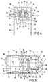
- Fig. 4
- eine Stirnansicht des Lötkontakts aus Fig. 1;
- Fig. 5
- eine Unteransicht des Lötkontakts aus Fig. 1.
- Fig. 6
- eine Seitenansicht eines zweiten Ausführungsbeispiels eines erfindungsgemäßen Lötkontakts mit weggeschnittener Seitenwand;
- Fig. 7
- eine Seitenansicht des Lötkontakts aus Fig. 6;
- Fig. 8
- eine Seitenansicht eines dritten Ausführungsbeispiels eines erfindungsgemäßen Lötkontakts;
- Fig. 9
- eine Draufsicht auf den Lötkontakt aus Fig. 9;
- Fig. 10
- eine Unteransicht des Lötkontakts aus Fig. 8;
- Fig. 11
- Federarme, die eine Kontaktstelle bilden, im Querschnitt längs der Linie A-A aus Fig. 10;
- Fig. 12
- eine Stirnansicht des Lötkontakts aus Fig. 8, die die Seite des Lötkontakts zeigt, an der der Bogenfederarmsteg angebunden ist; und
- Fig. 13
- eine Stirnseite des Lötkontakts aus Fig. 8, die die Seite der Kontaktstelle des Lötkontakts zeigt.
- Fig. 1
- a side view of an embodiment of a solder contact according to the invention with the side wall cut away;
- Fig. 2
- a side view of the solder contact of Fig. 1;
- Fig. 3
- a plan view of the solder contact of Fig. 1;
- Fig. 4
- an end view of the solder contact of Fig. 1;
- Fig. 5
- a bottom view of the solder contact of Fig. 1st
- Fig. 6
- a side view of a second embodiment of a solder contact according to the invention with cut away side wall;
- Fig. 7
- a side view of the solder contact of Fig. 6;
- Fig. 8
- a side view of a third embodiment of a solder contact according to the invention;
- Fig. 9
- a plan view of the solder contact of Fig. 9;
- Fig. 10
- a bottom view of the solder contact of Fig. 8;
- Fig. 11
- Spring arms, which form a contact point, in cross section along the line AA from Fig. 10;
- Fig. 12
- an end view of the solder contact of Figure 8, showing the side of the solder contact to which the bow spring arm web is connected. and
- Fig. 13
- 8, which shows the side of the contact point of the solder contact.
Ein erstes Ausführungsbeispiel eines erfindungsgemäßen Lötkontakts umfaßt zwei Seitenwandungen 1 und 2 sowie eine Deckenwandung 3 (Fig. 1-5). Die Seitenwandungen 1 und 2 sind rechtwinklig von der Deckenwandung 3 abgebogen, so daß eine Art nach unten offenes, im Querschnitt U-förmiges Gehäuse gebildet wird.A first exemplary embodiment of a solder contact according to the invention comprises two
Die Deckenwandung 3 weist eine freie, gerade verlaufende Hinterkante 4 und eine freie, halbkreisbogenförmig verlaufende Vorderkante 5 auf. Kurz vor der Hinterkante 4 ist in der Deckenwandung 3 eine parallel zur Hinterkante 4 verlaufende Sicke 6 eingedrückt, die sich ein Stück in die Seitenwandungen 1 und 2 erstreckt, so daß die U-Form des Gehäuses durch die Sicke 6 gegen Aufweitung versteift wird. Im Bereich der Vorderkante 5 ist in der Deckenwandung 3 ein Steckloch 7 von etwa 1,5 mm Durchmesser für das Durchstecken eines etwa 1 mm dicken Steckkontaktstifts (nicht dargstellt) ausgestanzt. Zwischen dem Steckloch 7 und der Sicke 6 kann in der Deckenwandung 3 durch einen zum Loch 7 weisenden U-förmigen Freischnitt 9 ein Anschlaglappen 8 ausgebildet sein, der rechtwinklig nach innen in das Gehäuse abgewinkelt ist.The
Die Seitenwandungen 1, 2 weisen eine freie gerade Hinterkante 10, 11, eine gerade Vorderkante 12, 13 sowie freie gerade Unterkanten 14, 15 auf. An jede Unterkante 14, 15 ist ein von der Kante vorstehendes Lötbein 16 angebunden und zwar in geringem Abstand von der Hinterkante 10 bzw. 11. In geringem Abstand neben jedem Lötbein 16 ist ein vorspringender Stützlappen 17 für die Abstützung des Gehäuses auf einer Leiterplatte 17a angebunden, dessen Funktion weiter unten erläutert wird.The
Die Seitenwandungen 1, 2 können zur Versteifung je eine parallel zur Hinterkante 10, 11 verlaufende Sicke 18 im Bereich zwischen dem Lötbein 16 und der Vorderkante 12 bzw. 13 aufweisen, die sich jeweils noch etwas in die Deckenwandung 3 erstreckt. Unter anderem zur Erleichterung der Biegung der Gehäuseform bei der Herstellung des Lötkontakts aus einer aus einem Blech gestanzten Platine sind Löcher 19, 19a an den Längskanten 20 im Übergangsbereich zwischen den Seitenwandungen 1, 2 und der Deckenwandung 3 ausgestanzt und zwar zweckmäßigerweise im Bereich zwischen den Sicken 6 und 18 sowie zwischen der Sicke 18 und der Vorderkante 12 bzw. 13. Die Seitenwandung 2 weist einen weiteren Anschlaglappen 21 auf, der durch einen parallel zur Unterkante 15 im Abstand davon verlaufenden, von der Vorderkante 13 her eingebrachten Einschnitt gebildet wird, wobei der Anschlaglappen 21 rechtwinklig in das Gehäuse derart abgebogen ist, daß sich seine zur Deckenwandung 3 weisende freie Längskante 21a im Abstand unter der freien Längskante 8a des Anschlaglappens 8 befindet.For stiffening, the
Die Funktion der Anschlaglappen 8, 21 wird weiter unten erläutert. In dem Anschlaglappen 21 ist in Längserstreckung des Lappens eine die Abbiegung überbrückende Versteifungssicke 22 eingedrückt; er weist außerdem an seiner Unterkante weitere, seitlich beabstandete Stützlappen 17 zur Abstützung des Anschlaglappens 21 auf der Leiterplatte 17a auf. In Richtung der Längsmittenachse des Gehäuses sind die Anschlaglappen 8 und 21 geringfügig zueinander versetzt, wobei der Anschlaglappen 8 näher zu den Hinterkanten 10, 11 und der Anschlaglappen 21 näher zu den Vorderkanten 12, 13 zu liegen kommt. Die Funktion der Relativlage der Anschlaglappen 8, 21 wird weiter unten näher erläutert.The function of the
Die Seitenwandung 1 weist einen rechteckigen Bogenfederarmsteg 23 auf, der von zwei von der Hinterkante 10 dieser Seitenwandung eingebrachten Einschnitten 24 und 25 gebildet ist und in etwa mittig zwischen der Deckenwandung 3 und der freien Unterkante 14 der Seitenwandung 1 verläuft. Ausgehend von seinem Anbindungsbereich an die Seitenwandung 1 verläuft der Bogenfederarmsteg 23 halbkreisförmig gebogen, und dieser Bogenbereich 26 steht über die Hinterkante 4 der Deckenwandung 3 geringfügig nach außen vor. Anschließend an den Bogenbereich 26 verläuft der Bogenfederarmsteg 23 parallel zu den Seitenwandungen 1 und 2 im Abstand von diesen in einer die Deckenwandung 3 lotrecht näher zur Seitenwandung 2 durchsetzenden Ebene. Am freien Ende des geraden Bogenfederarmstegbereichs 27 ist eine U-förmige Federarmbasis 28 angebunden, die einen zur Deckenwandung 3 ausgebogenen U-Basissteg 29 mit in Gehäuselängsrichtung verlaufender Bogenmantellinie und zwei parallel zu den Seitenwandungen 1, 2 verlaufende gerade U-Schenkel 30 und 31 aufweist, die beidseits über die Längskanten des geraden Bogenfederarmbereichs 27 vorstehen und von denen der Schenkel 31 in Verlängerung des geraden Bogenfederarmbereichs 27 liegt. Die Federarmbasis 28 ist wegen der außermittigen Lage des geraden Bogenfederarmbereichs 27 von den Seitenwandungen 1, 2 gleich weit beabstandet und liegt mit ihren Stirnkanten beabstandet zu den Anschlaglappen 8, 21. In die U-Schenkel 30, 31 und den U-Basissteg 29 ist eine durchgehende, U-förmige Sicke 32 eingedrückt, durch die die Federarmbasis 28 gegen Aufweitung versteift wird.The
An die zur Vorderkante 5 der Deckenwandung 3 weisenden Stirnkanten der beiden U-Schenkel 30 und 31 sind Konkaktfederarme 33 und 34 einstückig angebunden, die unter dem Steckloch 7 eine Kontaktstelle 35 festlegen. Durch parallel zueinander verlaufende Einschnitte im Anbindungsbereich der Kontaktfederarme 33, 34 an die U-Schenkel 30, 31 sind quer zur Längserstreckung verlaufend, von der Längskante der Federarme 33, 34 abgewinkelte Anschlaglappen 36 bis 39 festgelegt, die mit den Anschlagkanten 8a und 21a zusammenwirken. Die Federarm-Anschlaglappen 36 bis 39 sind um 90° von den Federarmen 33, 34 nach außen abgebogen und mit ihren freien Querkanten von den Anschlagkanten 8a, 21a beabstandet, so daß sich die Federarme 33, 34 frei durch die Verengung hindurch erstrecken, die durch die einander gegenüberliegenden Anschlaglappen 8 und 21 festgelegt ist. Die die Anschlaglappen 36 bis 39 festlegenden Einschnitte sind in Längsrichtung der Federarme 33, 34 derart voneinander beabstandet, daß die Federarm-Anschlaglappen 36 bis 39 auch in dieser Richtung einen Abstand zu den Anschlaglappen 8, 21 aufweisen. Der Anschlaglappen 8 liegt näher an den eingeschnittenen freien Stirnkanten der U-Schenkel 30, 31 als der Lappen 21, der seinerseits näher zu den kontaktstellenseitigen, durch die Einschnitte festgelegten Hinterkanten von Kontaktbereichen 40, 41 der Federarme liegt als der Lappen 8. Durch den Abstand der Anschlagkanten 8a, 21a zu den Anschlaglappen 36 bis 39 wird die Beweglichkeit des Bogenfederarmstegs 23 nach oben und unten begrenzt. Seitlich kann die Beweglichkeit des Bogenfederarmstegs durch die Seitenwandung 1, 2 oder durch einen Anschlag der Hinterkanten der Kontaktabschnitte 40, 41 an den Anschlaglappen 21 begrenzt sein.
Die Kontaktstelle 35 wird durch die Kontaktbereiche 40 und 41 der Kontaktfederarme 33, 34 festgelegt, die sich an die Anschlaglappen 36 bis 39 anschließen und das Steckloch 7 überspannen. Die Kontaktbereiche 40 und 41 sind um die Längsmittenachse des Gehäuses beidseits dieser Achse quer nach außen auf die Seitenwandungen 1, 2 zu abgebogen. Durch diese Biegung werden die Kontaktbereiche 40, 41 versteift und bilden außerdem einen dem Steckloch 7 gegenüberliegenden, sich zu diesem hin erweiternden Findungstrichter 42. Quer zu ihren zur Längsmittenachse parallelen Bogenmantellinien liegen sich die gekrümmten Kontakabschnitte 40, 41 mit minimalem Abstand gegenüber und bilden so die Kontaktstelle 35.The
An die Stirnkante des Kontaktbereichs 40 ist ein rechteckiger Bogenfedersteg 44 angebunden, der schmaler ist als der Kontaktbereich 40, und der mit seinem freien Ende 45 den anderen Kontaktbereich 41 seitlich von außen umgreift, und der mit seiner freien Stirnkante 43 in einer Ebene liegt, die das Stecklochzentrum durchsetzt. Der Abschnitt 46, mit dem der Bogenfedersteg 44 an der Außenseite des Kontaktbereichs 41 anliegt, ist ballig bzw. teilzylindrisch auf den Kontaktbereich 41 mit in Längsrichtung verlaufender Bogenmantellinie zu ausgebogen und bildet ein Widerlager, das von auf der Höhe der Kontaktstelle 35 außen gegen den Kontaktbereich 41 drückt. Durch den derart ausgebildeten Bogenfedersteg 44, der einstückig mit dem einen Kontaktbereich 40 verbunden ist und außen gegen den anderen Kontaktbereich 41 drückt, wird erreicht, daß bei Einführen des Steckkontaktstifts in die Kontaktstelle 35 über das Steckloch 7, dieser Stift im Kontaktbereich gefangengehalten wird. Die weiche Federkennlinie des Bogenfederstegs 44 wird durch ein Langloch 47 bestimmt, das sich von seinem Anbindungsbereich an den Kontaktbereich 40 bis zu seinem balligen Anlagebereich 45 erstreckt. Der Bogenfedersteg 44 erstreckt sich bis nahe zur Vorderkante 5 der Deckenwandung 3. Erreicht wird durch den Bogenfedersteg 44 eine dauerhaft feste Kontaktierung des Steckkontaktstifts.A rectangular
Der Bogenfederarmsteg 23 ist ebenfalls durch eine weiche Federkennlinie gekennzeichnet, die aus seiner großen Länge resultiert und durch die erreicht wird, daß die den Kontaktstift gefangenhaltende Kontaktstelle 35 dauerhaft beweglich ist, so daß Relativbewegungen zwischen dem Kontaktstift und der Kontaktstelle verhindert werden, indem die Kontaktstelle insbesondere in Steckachsrichtung sowie quer dazu beweglich ist, wodurch die Kontaktstelle 35 den Bewegungen des Kontaktstifts die im Rahmen der Bewegungsfreiheit der Federarme 33, 34 im Bereich ihrer Anschlaglappen 36 bis 39 gegenüber dem gehäusefesten Anschlaglappen 8, 21 folgen kann. Erfindungsgemäß wird die besonders schwingfähige Aufhängung der Kontaktstelle 35 bei einem kleinen Volumen des Lötkontakts aufgrund des langen Bogenfederarmstegs 23 erreicht, der alternativ zu der vorstehend beschriebenen Ausführungsform zusätzlich dadurch verlängert sein kann, daß sein Anbindungsbereich durch entsprechend tiefe Einschnitte noch weiter in die Seitenwandung 1 hineingelegt wird.The
Ein zweites Ausführungsbeispiel der Erfindung (Fig. 6, 7) hat einen Bogenfederarmsteg 23, der aus zwei dünnen Bogenschleifen 23a, 23b ausgebildet ist. Durch diese zwei dünnen Bogenschleifen 23a, 23b wird die Nachgiebigkeit und somit die Beweglichkeit der durch die Kontaktfederarme 33, 34 definierten Kontaktstelle gegenüber dem ersten Ausführungsbeispiel mit einem streifenförmigen Bogenfederarmsteg 23 wesentlich erhöht. Diese Beweglichkeit der Kontaktstelle 35 ermöglicht es, daß ein in der Kontaktstelle 35 befindlicher Kontaktsteckstift gegenüber dem Gehäuse des Lötkontaktes noch freier beweglich ist, insbesondere schwingen bzw. vibrieren kann, wobei der elektrische Kontakt nicht unterbrochen wird und die Bewegungsenergie des Kontaktsteckstiftes nicht oder nur zu einem sehr geringen Teil auf das Gehäuse des Lötkontaktes übertragen wird, so daß der Lötkontakt auf Dauer sicher an der Leiterplatte 17a befestigt ist.A second exemplary embodiment of the invention (FIGS. 6, 7) has a bow
Durch das Ausbilden des Bogenfederarmstegs 23 aus zwei dünnen Bogenschleifen 23a, 23b kann der Bogenbereich 26 mit einem kleineren Radius gebogen sein, so daß bei einer Anbindung der Bogenschleifen mit Einschnitten 24 und 25 der Bogen nicht nach außen über die Hinterkante 4 der Deckenwandung 3 vorsteht. Hierdurch wird ein seitlicher Schutz der Bogenschleifen 23a, 23b gewährleistet und die Gesamtlänge des Lötkontakts weiter verringert.By forming the bow
Im übrigen ist das zweite Ausführungsbeispiel der Erfindung (Fig. 6, 7) mit dem ersten Ausführungsbeispiel (Fig. 1 bis 5) identisch, wobei mit gleichen Bezugszeichen gleiche Teile an den Lötkontakten gekennzeichnet sind.Otherwise, the second exemplary embodiment of the invention (FIGS. 6, 7) is identical to the first exemplary embodiment (FIGS. 1 to 5), with the same reference numerals identifying the same parts on the solder contacts.
Ein drittes Ausführungsbeispiel der Erfindung (Fig. 8 bis 13) hat einen mäanderförmigen Federarmsteg 23 (Fig. 12). Der Federarmsteg 23 ist mit einem Bogenbereich 50 an die Seitenwandung 1 angebunden. Der Bogenbereich 50 des Bogenfederarmstegs 23 geht über in einen mäanderförmig geschlungenen Bereich mit geradlinig verlaufenden Bereichen 51a, 51c und 51e des Bogenfederarmstegs 23, die jeweils durch enge Bögen 51b und 51d miteinander verbunden sind. Dieser mäanderförmig verschlungene Bereich des Bogenfederarmstegs 23 erstreckt sich vom Bereich der Anbindung 50 an der Seitenwandung 1 nach hinten in Richtung zur Hinterkante 4, wobei der Bogenfederarmsteg in einen geradlinig senkrecht zur Seitenwandung 1 verlaufenden Bereich 54 übergeht, an dem sich ein weiterer Bogenbereich 53 anschließt, der in etwa in das Zentrum des Gehäuses des Lötkontakts führt, wo die U-förmige Federarmbasis 28 an den Bogenfederarmsteg 23 angebunden ist (Fig. 10). Zwischen dem Bogenfederarmsteg 23 und der Seitenwandung 2 besteht ein Freiraum, in dem sich der mäanderförmig ausgebildete Bogenfederarmsteg 23 elastisch verformen kann. Der derart mäanderförmig verlaufende Bogenfederarmsteg 23 liegt vollständig in dem Bereich, der durch die Seitenwandungen 1, 2 und der Deckenwandung 3 begrenzt ist. Das heißt, der Bogenfederarmsteg 23 steht nicht über die Hinterkante 4 der Deckenwandung 3 nach außen vor, wie es beim ersten Ausführungsbeispiel der Fall ist. Der mäanderförmig verlaufende Bereich des Bogenfederarmstegs 23, der sich vorzugsweise vom Bereich der Anbindung 50 bis in den Bogenbereich 53 erstreckt, verleiht dem Bogenfederarmsteg 23 eine weiche Kennlinie, so daß die durch die zwei Kontaktfederarme 33, 34 begrenzte Kontaktfederstelle 35 im Bezug zum Gehäuse des Lötkontakts fast frei beweglich ist, aber ohne daß die elektrische Verbindung, die von den Kontaktfederarmen 33, 34 über die Federarmbasis 28, dem Bogenfederarmsteg 23, dem Gehäuse mit den Seitenwandungen 1, 2 und der Deckenwandung 3 und den Lötbeinen 16 führt, unterbrochen wird.A third exemplary embodiment of the invention (FIGS. 8 to 13) has a meandering spring arm web 23 (FIG. 12). The
Durch parallel zueinander verlaufende Einschnitte im Anbindungsbereich der Kontaktfederarme 33, 34 an den U-Schenkeln 30, 31 sind quer zur Längsrichtung der Kontaktfederarme 33, 34 abgewinkelte Anschlaglappen 36 bis 39 ausgebildet. Diese Anschlaglappen 36 bis 39 wirken mit einem durch einen Freischnitt 9 in der Deckenwandung 3 freigeschnittenen Lappen 8 zusammen, der die Bewegung der Kontaktfederarme 33, 34 in Richtung zur Deckenwandung 3 begrenzt und wirken ferner mit einem Steg 55 zusammen, der an die Seitenwandung 2 angebunden und von der Seitenwandung 2 zur Seitenwandung 1 sich etwa im rechten Winkel zu den Seitenwandungen 1, 2 erstreckt, durch den die Bewegung der Kontaktfederarme 33, 34 in Richtung weg von der Deckenwandung 3 begrenzt wird. Der Steg 55 liegt vorzugsweise in einem Einschnitt 57 in der Seitenwandung 1, so daß seine Lage fixiert ist, die in diesem Ausführungsbeispiel nicht in Längsrichtung des Lötkontakts zum Lappen 8 versetzt ist. Der Lappen 8 und der Steg 55 sind mit Abstand zu den jeweiligen Anschlaglappen 36 bis 39 angeordnet, so daß die Kontaktfederarme 33, 34 nach oben und unten ein Spiel haben. Die Deckenwandung 3 erstreckt sich nicht über die Kontaktstelle 35, sondern hat eine Vorderkante 5 mit einem Bogenbereich 5a, über den die Kontaktfederarme 33, 34 vorstehen.By incisions running parallel to each other in the connection area of the
Die Kontaktfederarme 33, 34 bilden in ihrem mittigen Bereich Kontaktbereiche 40 und 41, an die sich jeweils nach außen gebogene Lappen 40a und 41a anschließen, um so einen Findungstrichter für einen Kontaktsteckstift zu bilden. Die Kontaktbereiche 40, 41 sind wiederum mit einem Bogenfedersteg 44 verbunden, der an den Kontaktbereich 41 angebunden ist und außen gegen den anderen Kontaktbereich 40 drückt. Am Kontaktbereich 40 ist ferner ein Lappen 56 angebunden, der schräg nach vorne in Richtung zum gegenüberliegenden Kontaktbereich 41 steht, so daß die Kontaktstelle 35 nach vorne begrenzt ist.In their central region, the
Durch die Ausbildung des Bogenfederarmstegs 23 aus Bogenschleifen bzw. mäanderförmigen Bogenfederarmsteg 23 wird die Federkennlinie gegenüber dem ersten Ausführungsbeispiel deutlich weicher, so daß die Kontaktstelle fast völlig unabhängig vom Gehäuse des Lötkontakts bewegt werden kann und nur nach oben und unten durch die Lappen 8, 21 bzw. den Lappen 8 und den Steg 55 und seitlich durch die Seitenwandungen 1, 2 begrenzt ist, an die die Lappen 40a, 41a der Kontaktfederarme 33, 34 anstoßen. Durch die weiche Kennlinie ist es ferner nicht notwendig, die Wandungen 1, 2 und 3 des Gehäuses durch Sicken oder dergleichen zu verstärken, da die von einem Kontaktsteckstift auf die Wandungen über die Kontaktfederarme ausgeübten Kräfte sehr gering sind. Dies vereinfacht den Herstellungsvorgang und vermindert somit die Herstellungskosten des Lötkontakts.The spring characteristic becomes by the formation of the bow
Claims (19)
dadurch gekennzeichnet,
daß die die Kontaktstelle (35) begrenzenden Kontaktfederarme (33, 34) mit einem Bogenfederarmsteg (23) an eine der Gehäusewandungen (1, 2, 3) angebunden sind und sich der Bogenfederarmsteg (23) frei in das Gehäuse bogenförmig erstreckt, so daß die durch die Kontaktfederarme (33, 34) begrenzte Kontaktstelle (35) in Steckachsrichtung eines Kontaktstiftes und/oder quer dazu beweglich angeordnet ist.Solder contact made of a stamped sheet metal part with a housing with housing walls (1, 2, 3) and with a movably arranged contact point (35) delimited by two contact spring arms (33, 34) for contacting a contact pin, the housing at least one through a hole in a printed circuit board has pluggable soldering leg (16),
characterized,
that the contact point (35) delimiting contact spring arms (33, 34) with an arc spring arm web (23) are connected to one of the housing walls (1, 2, 3) and the arch spring arm web (23) extends freely into the housing so that the by the contact spring arms (33, 34) delimited contact point (35) in the thru-axis direction of a contact pin and / or transversely thereto.
dadurch gekennzeichnet,
daß der Bogenfederarmsteg (23) streifenförmig ausgebildet ist.Solder contact according to claim 1,
characterized,
that the bow spring arm web (23) is strip-shaped.
dadurch gekennzeichnet,
daß der Bogenfederarmsteg (23) durch zwei dünne Bogenschleifen (23a, 23b) ausgebildet ist.Solder contact according to claim 1 or 2,
characterized,
that the bow spring arm web (23) is formed by two thin bow loops (23a, 23b).
dadurch gekennzeichnet,
daß der Bogenfederarmsteg (23) mäanderförmig ausgebildet ist.Solder contact according to one or more of claims 1 to 3,
characterized,
that the bow spring arm web (23) is meandering.
dadurch gekennzeichnet,
daß die Steckachsrichtung des Kontaktsteckstiftes quer zur Längsrichtung des Lötkontakts ist.Solder contact according to one or more of claims 1 to 4,
characterized,
that the plug axis direction of the contact pin is transverse to the longitudinal direction of the solder contact.
dadurch gekennzeichnet,
daß die Steckachsrichtung des Kontaktstiftes parallel zur Steckachsrichtung des Lötbeins (16) verläuft.Solder contact according to claim 5,
characterized,
that the plug axis direction of the contact pin runs parallel to the plug axis direction of the solder leg (16).
dadurch gekennzeichnet,
daß in der Gehäusewandung (1, 2), an der der Bogenfederarmsteg (23) angebunden ist, Einschnitte (24, 25) eingebracht sind, durch die der Bogenfederarmsteg (23) verlängert wird.Solder contact according to one or more of claims 1 to 6,
characterized,
that incisions (24, 25) are made in the housing wall (1, 2) to which the bow spring arm web (23) is connected, by means of which the bow spring arm web (23) is extended.
dadurch gekennzeichnet,
daß der Bogenfederarmsteg (23) sich von der Gehäusewandung (1, 2), an der er angebunden ist, in einem Halbkreisbogen in das Gehäuse des Lötkontakts erstreckt.Solder contact according to one or more of claims 1 to 7,
characterized,
that the bow spring arm web (23) extends from the housing wall (1, 2), to which it is connected, in a semicircular arc into the housing of the solder contact.
dadurch gekennzeichnet,
daß sich an den Halbkreisbogen ein geradlinig verlaufender Bereich (27) des Bogenfederarmstegs (23) anschließt, an dem eine U-förmige Federarmbasis (28) einstückig angebunden ist, die zwei gerade U-Schenkel (30, 31) aufweist, an die jeweils einer der Kontaktfederarme (33, 34) angebunden ist, wobei die Federarmbasis (18) zwischen dem Bogenfederarmsteg (23) und den Kontaktfederarmen (33, 34) angeordnet ist.Solder contact according to claim 8,
characterized,
that a rectilinear region (27) of the bow spring arm web (23) adjoins the semicircular arch, to which a U-shaped spring arm base (28) is integrally connected, which has two straight U-legs (30, 31), each of which the contact spring arms (33, 34) is connected, the spring arm base (18) being arranged between the bow spring arm web (23) and the contact spring arms (33, 34).
dadurch gekennzeichnet,
daß die Beweglichkeit der Federarme (33, 34) bzw. der Kontaktstelle (35) durch gehäusefeste Anschlaglappen (8, 21) bzw. durch einen gehäusefesten Anschlaglappen (8) und einen gehäusefesten Steg (55) begrenzt ist, die jeweils einander in Steckachsrichtung des Kontaktsteckstifts gegenüberliegend quer zu den Federarmen (33, 34) verlaufend angeordnet sind.Solder contact according to one or more of claims 1 to 9,
characterized,
that the mobility of the spring arms (33, 34) or the contact point (35) through housing-fixed stop tabs (8, 21) or is bounded by a stop tab (8) fixed to the housing and a web (55) fixed to the housing, each of which is arranged opposite one another in the direction of the plug-in axis of the contact pin and extends transversely to the spring arms (33, 34).
dadurch gekennzeichnet,
daß das Gehäuse einen U-förmigen Querschnitt hat mit einer Deckenwandung (3) und zwei sich gegenüberliegende Seitenwandungen (1, 2), an die Lötbeine (16) an deren freien Unterkanten (14, 15) angebunden sind, die vorzugsweise in den Ebenen der Seitenwandungen (1, 2) liegen, wobei der Bogenfederarmsteg (23) an eine Seitenwandung (1, 2) angebunden ist.Solder contact according to one or more of claims 1 to 10,
characterized,
that the housing has a U-shaped cross section with a top wall (3) and two opposite side walls (1, 2), to the solder legs (16) on their free lower edges (14, 15), which are preferably in the planes of Side walls (1, 2) are located, the bow spring arm web (23) being connected to a side wall (1, 2).
dadurch gekennzeichnet,
daß die Kontaktfederarme (33, 34) aus quer zur Steckachsrichtung des Kontaktstiftes verlaufenden Kontaktbereichen (40, 41) ausgebildet sind, an die in Steckachsrichtung nach außen gebogene Lappen (40a, 41a) angebunden sind, so daß sie einen Findungstrichter für den Kontaktstift bilden.Solder contact according to one or more of claims 1 to 11,
characterized,
that the contact spring arms (33, 34) are formed from contact regions (40, 41) extending transversely to the direction of the plug pin, to which tabs (40a, 41a) bent outwards in the direction of the plug axis are connected, so that they form a finding funnel for the contact pin.
dadurch gekennzeichnet,
daß an einem der Kontaktfederarme (33, 34) ein Bogenfedersteg (44) angebunden ist, der sich von der der Federarmbasis gegenüberliegenden Seite in einem Bogen um das entsprechende Ende des gegenüberliegenden Kontaktfederarms (33, 34) erstreckt, so daß der Bogenfedersteg (44) diesen seitlich umgreift und an ihm außen im Bereich der Kontaktstelle (35) anliegt.Solder contact according to one or more of claims 1 to 12,
characterized,
that an arc spring web (44) is connected to one of the contact spring arms (33, 34) and extends from the side opposite the spring arm base in an arc around the corresponding end of the opposite contact spring arm (33, 34), so that the arc spring web (44) grips it laterally and rests against it outside in the area of the contact point (35).
dadurch gekennzeichnet,
daß der Bogenfedersteg (44) ein Langloch (47) aufweist, das sich im wesentlichen über seine gesamte Länge erstreckt.Solder contact according to claim 13,
characterized,
that the bow spring web (44) has an elongated hole (47), the extends essentially over its entire length.
dadurch gekennzeichnet,
daß einer der Anschlaglappen (8) durch einen U-förmigen Freischnitt in einer der Gehäusewandungen (1, 2) verbindenden Deckenwandung (3) freigeschnitten und in das Gehäuse gebogen ist.Solder contact according to claim 10 or claim 10 and one or more of claims 11 to 14,
characterized,
that one of the stop tabs (8) is cut free by a U-shaped cut in one of the housing walls (1, 2) connecting the ceiling wall (3) and bent into the housing.
dadurch gekennzeichnet,
daß einer der gehäusefesten Anschlaglappen (21) oder der gehäusefeste Steg (55) aus einer der Gehäusewandungen (1, 2) frei- bzw. ausgeschnitten ist und in das Gehäuse gebogen ist und vorzugsweise einen rechteckigen Lappen bildet.Solder contact according to claim 10 or according to claim 10 and one or more of claims 11 to 15,
characterized,
that one of the stop flaps (21) fixed to the housing or the web (55) fixed to the housing is cut free or cut out of one of the housing walls (1, 2) and is bent into the housing and preferably forms a rectangular tab.
dadurch gekennzeichnet,
daß der gehäusefeste Steg (55) sich von der Gehäusewandung, an der er frei- bzw. ausgeschnitten ist, bis zur gegenüberliegenden Gehäusewandung (1, 2) erstreckt und diese in einem Einschnitt (55) durchsetzt.Solder contact according to claim 16,
characterized,
that the housing-fixed web (55) extends from the housing wall on which it is free or cut out to the opposite housing wall (1, 2) and passes through it in an incision (55).
dadurch gekennzeichnet,
daß sich die Deckenwandung (3) über die Kontaktstelle (35) erstreckt und ein Steckloch (7) für den freien Durchtritt eines Kontaktsteckstiftes aufweist.Solder contact according to claim 11 or claim 11 and one or more of claims 12 to 17,
characterized,
that the top wall (3) extends over the contact point (35) and has a plug hole (7) for the free passage of a contact pin.
dadurch gekennzeichnet,
daß die gehäusefesten Anschlaglappen (8, 21) bzw. der gehäusefeste Anschlaglappen (8) und der gehäusefeste Steg (55) in Richtung der Gehäuselängsachse versetzt zueinander angeordnet sind.Solder contact according to claim 10 or claim 10 and one or more of claims 11 to 18,
characterized,
that the housing-fixed stop tabs (8, 21) or the housing-fixed Stop flaps (8) and the housing-fixed web (55) are arranged offset to one another in the direction of the housing longitudinal axis.
Applications Claiming Priority (2)
| Application Number | Priority Date | Filing Date | Title |
|---|---|---|---|
| DE4326456 | 1993-08-06 | ||
| DE4326456A DE4326456A1 (en) | 1993-08-06 | 1993-08-06 | Solder contact |
Publications (3)
| Publication Number | Publication Date |
|---|---|
| EP0637854A2 true EP0637854A2 (en) | 1995-02-08 |
| EP0637854A3 EP0637854A3 (en) | 1995-10-25 |
| EP0637854B1 EP0637854B1 (en) | 1999-01-27 |
Family
ID=6494615
Family Applications (1)
| Application Number | Title | Priority Date | Filing Date |
|---|---|---|---|
| EP94110947A Expired - Lifetime EP0637854B1 (en) | 1993-08-06 | 1994-07-14 | Soldering terminal |
Country Status (4)
| Country | Link |
|---|---|
| US (1) | US5597332A (en) |
| EP (1) | EP0637854B1 (en) |
| JP (1) | JPH07320802A (en) |
| DE (2) | DE4326456A1 (en) |
Cited By (2)
| Publication number | Priority date | Publication date | Assignee | Title |
|---|---|---|---|---|
| GB2306807A (en) * | 1995-10-24 | 1997-05-07 | Modelec Sa | Socket contact for an electrical connector |
| US5679010A (en) * | 1994-12-20 | 1997-10-21 | The Whitaker Corporation | Anti-fretting terminal for PCB |
Families Citing this family (11)
| Publication number | Priority date | Publication date | Assignee | Title |
|---|---|---|---|---|
| JP3412539B2 (en) * | 1998-11-30 | 2003-06-03 | 住友電装株式会社 | Electrical connection structure |
| US6511336B1 (en) * | 2000-05-25 | 2003-01-28 | Illinois Tool Works Inc. | Solderless flex termination for motor tab |
| DE102004062879A1 (en) * | 2004-12-27 | 2006-07-06 | Lear Corp., Southfield | Electrical contact for servo-motor, has flat spring unit fastened with flexible edgewise spring unit, where contact unit is made of sheet metal and metal planes of spring units are perpendicular to each other |
| JP4913539B2 (en) * | 2006-10-25 | 2012-04-11 | 日本圧着端子製造株式会社 | Socket contact |
| JP4889118B2 (en) * | 2007-06-07 | 2012-03-07 | 株式会社ヨコオ | Electrical connector |
| US20090109691A1 (en) * | 2007-10-24 | 2009-04-30 | Yung-Yi Chuang | Bent fixing structure for light emitting component |
| KR100952773B1 (en) * | 2008-04-22 | 2010-04-14 | 현대자동차주식회사 | Terminal for connecting bus bar to printed circuit board |
| KR101390960B1 (en) * | 2013-03-29 | 2014-05-02 | 몰렉스 인코포레이티드 | Poke in connector |
| WO2016099572A1 (en) * | 2014-12-20 | 2016-06-23 | Intel Corporation | Solder contacts for socket assemblies |
| DE102020214324A1 (en) | 2020-11-13 | 2022-05-19 | Brose Fahrzeugteile SE & Co. Kommanditgesellschaft, Würzburg | Electronics unit for an electric refrigerant drive |
| DE102021115583A1 (en) * | 2021-06-16 | 2022-12-22 | Te Connectivity Germany Gmbh | Electrical high-voltage PCB plug-in contact device and power electrical PCB connection |
Citations (5)
| Publication number | Priority date | Publication date | Assignee | Title |
|---|---|---|---|---|
| DE3414323A1 (en) * | 1984-04-16 | 1985-10-24 | Siemens AG, 1000 Berlin und 8000 München | Electrical plug connector |
| DE3729546A1 (en) * | 1986-09-12 | 1988-03-24 | Burndy Electra Spa | Miniaturised female electrical contact element for plug connections for printed circuits |
| DE3633799A1 (en) * | 1986-10-03 | 1988-04-07 | Grote & Hartmann | FILM CONNECTOR FOR PRINTED CIRCUITS |
| DE4109519A1 (en) * | 1991-03-22 | 1992-09-24 | Grote & Hartmann | Solder contact for connecting pin to PCB - has pliable contacts to receive pin and legs to insert and solder in PCB and is movable in insert direction and perpendicular to it |
| DE4103423C2 (en) * | 1990-02-06 | 1993-04-15 | Grote & Hartmann Gmbh & Co Kg, 5600 Wuppertal, De |
Family Cites Families (17)
| Publication number | Priority date | Publication date | Assignee | Title |
|---|---|---|---|---|
| US4012107A (en) * | 1975-12-17 | 1977-03-15 | Amp Incorporated | Female terminals |
| DE7638508U1 (en) * | 1976-12-09 | 1977-04-28 | Grote & Hartmann Gmbh & Co Kg, 5600 Wuppertal | CLIP SPRING FOR PRINTED CIRCUITS |
| US4080037A (en) * | 1977-01-06 | 1978-03-21 | Amp Incorporated | Receptacle terminal for printed circuit board |
| JPS6021894Y2 (en) * | 1981-10-06 | 1985-06-29 | 星電器製造株式会社 | thin jack |
| US4548447A (en) * | 1984-04-05 | 1985-10-22 | Magnetic Controls Company | Electrical jack |
| DE3613675A1 (en) * | 1985-02-23 | 1987-10-29 | Bbc Brown Boveri & Cie | Plug device for semiconductor modules |
| US4664458A (en) * | 1985-09-19 | 1987-05-12 | C W Industries | Printed circuit board connector |
| US4892492A (en) * | 1988-06-17 | 1990-01-09 | Modular Computer Systems, Inc. | Device with openings for receiving pins of electrical components |
| US4904192A (en) * | 1989-01-05 | 1990-02-27 | Motorola, Inc. | Battery contacts |
| DE3922237A1 (en) * | 1989-07-06 | 1991-01-10 | Hirschmann Richard Gmbh Co | Circuit board connection socket - has bush coupled by flexible link to integral housing soldered onto board |
| FR2652227B1 (en) * | 1989-09-19 | 1996-08-02 | Legrand Sa | PRINTED CIRCUIT BOARD WITH SHIELDING COVER. |
| DE4034423C2 (en) * | 1989-10-30 | 1998-10-08 | Amp Inc | Circuit board contact |
| DE9001340U1 (en) * | 1990-02-06 | 1991-06-06 | Grote & Hartmann Gmbh & Co Kg, 5600 Wuppertal, De | |
| US5035650A (en) * | 1990-06-15 | 1991-07-30 | Amp Incorporated | Electrical connector having an inner metal shield |
| DE9105408U1 (en) * | 1991-05-02 | 1991-07-18 | Elco Elektronik Gmbh, 5240 Betzdorf, De | |
| JP3016164B2 (en) * | 1991-06-19 | 2000-03-06 | 日本エー・エム・ピー株式会社 | Movable connector |
| JP2513945Y2 (en) * | 1991-06-26 | 1996-10-09 | ホシデン株式会社 | connector |
-
1993
- 1993-08-06 DE DE4326456A patent/DE4326456A1/en not_active Withdrawn
-
1994
- 1994-07-14 EP EP94110947A patent/EP0637854B1/en not_active Expired - Lifetime
- 1994-07-14 DE DE59407723T patent/DE59407723D1/en not_active Expired - Lifetime
- 1994-08-05 JP JP6204389A patent/JPH07320802A/en active Pending
- 1994-08-05 US US08/286,704 patent/US5597332A/en not_active Expired - Fee Related
Patent Citations (5)
| Publication number | Priority date | Publication date | Assignee | Title |
|---|---|---|---|---|
| DE3414323A1 (en) * | 1984-04-16 | 1985-10-24 | Siemens AG, 1000 Berlin und 8000 München | Electrical plug connector |
| DE3729546A1 (en) * | 1986-09-12 | 1988-03-24 | Burndy Electra Spa | Miniaturised female electrical contact element for plug connections for printed circuits |
| DE3633799A1 (en) * | 1986-10-03 | 1988-04-07 | Grote & Hartmann | FILM CONNECTOR FOR PRINTED CIRCUITS |
| DE4103423C2 (en) * | 1990-02-06 | 1993-04-15 | Grote & Hartmann Gmbh & Co Kg, 5600 Wuppertal, De | |
| DE4109519A1 (en) * | 1991-03-22 | 1992-09-24 | Grote & Hartmann | Solder contact for connecting pin to PCB - has pliable contacts to receive pin and legs to insert and solder in PCB and is movable in insert direction and perpendicular to it |
Cited By (2)
| Publication number | Priority date | Publication date | Assignee | Title |
|---|---|---|---|---|
| US5679010A (en) * | 1994-12-20 | 1997-10-21 | The Whitaker Corporation | Anti-fretting terminal for PCB |
| GB2306807A (en) * | 1995-10-24 | 1997-05-07 | Modelec Sa | Socket contact for an electrical connector |
Also Published As
| Publication number | Publication date |
|---|---|
| US5597332A (en) | 1997-01-28 |
| JPH07320802A (en) | 1995-12-08 |
| DE59407723D1 (en) | 1999-03-11 |
| EP0637854B1 (en) | 1999-01-27 |
| EP0637854A3 (en) | 1995-10-25 |
| DE4326456A1 (en) | 1995-02-09 |
Similar Documents
| Publication | Publication Date | Title |
|---|---|---|
| DE102013223570B4 (en) | Pin contact with a contact body manufactured as a stamped and bent part and a solid contact pin | |
| EP0196367B1 (en) | Box-like formed spring | |
| EP0433610B1 (en) | Electrical contact element with surrounding spring | |
| DE4001857C2 (en) | ||
| EP0577927A1 (en) | Electrical contact element | |
| EP0637854B1 (en) | Soldering terminal | |
| EP0628219B1 (en) | Contact spring with an engagement sleeve in the form of an over-spring | |
| DE3435822C2 (en) | Jack socket with embedded contact elements | |
| DE3928751C2 (en) | ||
| DE19536500A1 (en) | Bush contact with spring arrangement for motor vehicle power contacts | |
| DE10318182B4 (en) | Plug contact and method for forming the same | |
| DE19826828C2 (en) | One-piece contact spring | |
| EP0536523A2 (en) | Terminal | |
| EP0738028A1 (en) | Flat pin | |
| WO1998059394A1 (en) | Flat plug contact organ for electrical connectors | |
| DE69913397T2 (en) | insulation displacement terminal | |
| EP0267145B1 (en) | Cutting and clamping terminal for an electrical conductor | |
| EP0099035A2 (en) | Resilient contact for electrical plug and socket connections | |
| DE4400702A1 (en) | Single-piece plug device | |
| DE4306795C2 (en) | Contact element | |
| DE4244776C2 (en) | Miniaturised electrical contact element | |
| DE3030911A1 (en) | Vehicle steering column mounted switch - has arm swung above spring-loaded contact strip to operate window washers and wiper | |
| EP0000163A1 (en) | Cable lug with spring | |
| DE202006017447U1 (en) | Flat plug sleeve consists of conductor connecting sectin and socket-shaped contact region for complementary contact blade, with side of second plate-shaped second contact zone connection in industrial applications | |
| DE4340377A1 (en) | Electrical contact element for use with conductor wire |
Legal Events
| Date | Code | Title | Description |
|---|---|---|---|
| PUAI | Public reference made under article 153(3) epc to a published international application that has entered the european phase |
Free format text: ORIGINAL CODE: 0009012 |
|
| AK | Designated contracting states |
Kind code of ref document: A2 Designated state(s): DE FR GB IT |
|
| ITCL | It: translation for ep claims filed |
Representative=s name: ING. A. GIAMBROCONO & C. S.R.L. |
|
| EL | Fr: translation of claims filed | ||
| GBC | Gb: translation of claims filed (gb section 78(7)/1977) | ||
| PUAL | Search report despatched |
Free format text: ORIGINAL CODE: 0009013 |
|
| AK | Designated contracting states |
Kind code of ref document: A3 Designated state(s): DE FR GB IT |
|
| 17P | Request for examination filed |
Effective date: 19951006 |
|
| 17Q | First examination report despatched |
Effective date: 19970922 |
|
| GRAG | Despatch of communication of intention to grant |
Free format text: ORIGINAL CODE: EPIDOS AGRA |
|
| GRAG | Despatch of communication of intention to grant |
Free format text: ORIGINAL CODE: EPIDOS AGRA |
|
| GRAG | Despatch of communication of intention to grant |
Free format text: ORIGINAL CODE: EPIDOS AGRA |
|
| GRAH | Despatch of communication of intention to grant a patent |
Free format text: ORIGINAL CODE: EPIDOS IGRA |
|
| GRAH | Despatch of communication of intention to grant a patent |
Free format text: ORIGINAL CODE: EPIDOS IGRA |
|
| GRAH | Despatch of communication of intention to grant a patent |
Free format text: ORIGINAL CODE: EPIDOS IGRA |
|
| GRAH | Despatch of communication of intention to grant a patent |
Free format text: ORIGINAL CODE: EPIDOS IGRA |
|
| GRAA | (expected) grant |
Free format text: ORIGINAL CODE: 0009210 |
|
| AK | Designated contracting states |
Kind code of ref document: B1 Designated state(s): DE FR GB IT |
|
| GBT | Gb: translation of ep patent filed (gb section 77(6)(a)/1977) |
Effective date: 19990205 |
|
| ET | Fr: translation filed | ||
| REF | Corresponds to: |
Ref document number: 59407723 Country of ref document: DE Date of ref document: 19990311 |
|
| ITF | It: translation for a ep patent filed |
Owner name: ING. A. GIAMBROCONO & C. S.R.L. |
|
| PLBE | No opposition filed within time limit |
Free format text: ORIGINAL CODE: 0009261 |
|
| STAA | Information on the status of an ep patent application or granted ep patent |
Free format text: STATUS: NO OPPOSITION FILED WITHIN TIME LIMIT |
|
| 26N | No opposition filed | ||
| PGFP | Annual fee paid to national office [announced via postgrant information from national office to epo] |
Ref country code: GB Payment date: 20010711 Year of fee payment: 8 |
|
| PGFP | Annual fee paid to national office [announced via postgrant information from national office to epo] |
Ref country code: FR Payment date: 20010727 Year of fee payment: 8 |
|
| REG | Reference to a national code |
Ref country code: GB Ref legal event code: IF02 |
|
| PGFP | Annual fee paid to national office [announced via postgrant information from national office to epo] |
Ref country code: DE Payment date: 20020626 Year of fee payment: 9 |
|
| PG25 | Lapsed in a contracting state [announced via postgrant information from national office to epo] |
Ref country code: GB Free format text: LAPSE BECAUSE OF NON-PAYMENT OF DUE FEES Effective date: 20020714 |
|
| GBPC | Gb: european patent ceased through non-payment of renewal fee |
Effective date: 20020714 |
|
| PG25 | Lapsed in a contracting state [announced via postgrant information from national office to epo] |
Ref country code: FR Free format text: LAPSE BECAUSE OF NON-PAYMENT OF DUE FEES Effective date: 20030331 |
|
| REG | Reference to a national code |
Ref country code: FR Ref legal event code: ST |
|
| PG25 | Lapsed in a contracting state [announced via postgrant information from national office to epo] |
Ref country code: DE Free format text: LAPSE BECAUSE OF THE APPLICANT RENOUNCES Effective date: 20040115 |
|
| PG25 | Lapsed in a contracting state [announced via postgrant information from national office to epo] |
Ref country code: IT Free format text: LAPSE BECAUSE OF NON-PAYMENT OF DUE FEES;WARNING: LAPSES OF ITALIAN PATENTS WITH EFFECTIVE DATE BEFORE 2007 MAY HAVE OCCURRED AT ANY TIME BEFORE 2007. THE CORRECT EFFECTIVE DATE MAY BE DIFFERENT FROM THE ONE RECORDED. Effective date: 20050714 |