EP0637700A2 - Carbon fiber reinforced resin coil spring and method for manufacturing the same - Google Patents
Carbon fiber reinforced resin coil spring and method for manufacturing the same Download PDFInfo
- Publication number
- EP0637700A2 EP0637700A2 EP94305779A EP94305779A EP0637700A2 EP 0637700 A2 EP0637700 A2 EP 0637700A2 EP 94305779 A EP94305779 A EP 94305779A EP 94305779 A EP94305779 A EP 94305779A EP 0637700 A2 EP0637700 A2 EP 0637700A2
- Authority
- EP
- European Patent Office
- Prior art keywords
- coil spring
- fibers
- cord
- prepregs
- carbon fibers
- Prior art date
- Legal status (The legal status is an assumption and is not a legal conclusion. Google has not performed a legal analysis and makes no representation as to the accuracy of the status listed.)
- Granted
Links
- 229920000049 Carbon (fiber) Polymers 0.000 title claims abstract description 65
- 239000004917 carbon fiber Substances 0.000 title claims abstract description 65
- 229920005989 resin Polymers 0.000 title claims abstract description 49
- 239000011347 resin Substances 0.000 title claims abstract description 49
- VNWKTOKETHGBQD-UHFFFAOYSA-N methane Chemical compound C VNWKTOKETHGBQD-UHFFFAOYSA-N 0.000 title claims abstract description 33
- 238000000034 method Methods 0.000 title claims description 24
- 238000004519 manufacturing process Methods 0.000 title claims description 10
- 239000000835 fiber Substances 0.000 claims abstract description 59
- 238000004804 winding Methods 0.000 claims description 6
- 239000004744 fabric Substances 0.000 claims description 5
- 230000001105 regulatory effect Effects 0.000 claims description 5
- 239000011159 matrix material Substances 0.000 claims description 3
- 238000010030 laminating Methods 0.000 claims description 2
- 238000010438 heat treatment Methods 0.000 claims 1
- 230000006835 compression Effects 0.000 abstract description 7
- 238000007906 compression Methods 0.000 abstract description 7
- 238000012360 testing method Methods 0.000 description 15
- 238000010008 shearing Methods 0.000 description 12
- 239000012783 reinforcing fiber Substances 0.000 description 10
- 239000000463 material Substances 0.000 description 6
- 230000000052 comparative effect Effects 0.000 description 5
- 239000003822 epoxy resin Substances 0.000 description 4
- 229920000647 polyepoxide Polymers 0.000 description 4
- 229920001187 thermosetting polymer Polymers 0.000 description 4
- 239000011116 polymethylpentene Substances 0.000 description 3
- 229920000306 polymethylpentene Polymers 0.000 description 3
- IISBACLAFKSPIT-UHFFFAOYSA-N bisphenol A Chemical compound C=1C=C(O)C=CC=1C(C)(C)C1=CC=C(O)C=C1 IISBACLAFKSPIT-UHFFFAOYSA-N 0.000 description 2
- 238000009730 filament winding Methods 0.000 description 2
- 239000002184 metal Substances 0.000 description 2
- 229910052751 metal Inorganic materials 0.000 description 2
- 239000009719 polyimide resin Substances 0.000 description 2
- 238000009864 tensile test Methods 0.000 description 2
- 229920005992 thermoplastic resin Polymers 0.000 description 2
- 239000004677 Nylon Substances 0.000 description 1
- 239000004696 Poly ether ether ketone Substances 0.000 description 1
- 239000004697 Polyetherimide Substances 0.000 description 1
- 229920000297 Rayon Polymers 0.000 description 1
- 239000004809 Teflon Substances 0.000 description 1
- 229920006362 Teflon® Polymers 0.000 description 1
- 239000004760 aramid Substances 0.000 description 1
- 229920006231 aramid fiber Polymers 0.000 description 1
- 229920003235 aromatic polyamide Polymers 0.000 description 1
- 229940106691 bisphenol a Drugs 0.000 description 1
- 239000000805 composite resin Substances 0.000 description 1
- 230000007547 defect Effects 0.000 description 1
- -1 for example Substances 0.000 description 1
- 239000012634 fragment Substances 0.000 description 1
- 239000011521 glass Substances 0.000 description 1
- 239000003365 glass fiber Substances 0.000 description 1
- 150000002739 metals Chemical class 0.000 description 1
- 238000000465 moulding Methods 0.000 description 1
- 229920001778 nylon Polymers 0.000 description 1
- 230000002093 peripheral effect Effects 0.000 description 1
- 229920001643 poly(ether ketone) Polymers 0.000 description 1
- 229920005668 polycarbonate resin Polymers 0.000 description 1
- 239000004431 polycarbonate resin Substances 0.000 description 1
- 229920000728 polyester Polymers 0.000 description 1
- 229920002530 polyetherether ketone Polymers 0.000 description 1
- 229920001601 polyetherimide Polymers 0.000 description 1
- 239000004848 polyfunctional curative Substances 0.000 description 1
- 229920001721 polyimide Polymers 0.000 description 1
- 239000002964 rayon Substances 0.000 description 1
- 239000011208 reinforced composite material Substances 0.000 description 1
- 230000003014 reinforcing effect Effects 0.000 description 1
- 239000012779 reinforcing material Substances 0.000 description 1
- 229920002050 silicone resin Polymers 0.000 description 1
- 239000007787 solid Substances 0.000 description 1
- 229920006259 thermoplastic polyimide Polymers 0.000 description 1
- 229920006337 unsaturated polyester resin Polymers 0.000 description 1
- 239000002759 woven fabric Substances 0.000 description 1
Images


Classifications
-
- B—PERFORMING OPERATIONS; TRANSPORTING
- B29—WORKING OF PLASTICS; WORKING OF SUBSTANCES IN A PLASTIC STATE IN GENERAL
- B29C—SHAPING OR JOINING OF PLASTICS; SHAPING OF MATERIAL IN A PLASTIC STATE, NOT OTHERWISE PROVIDED FOR; AFTER-TREATMENT OF THE SHAPED PRODUCTS, e.g. REPAIRING
- B29C53/00—Shaping by bending, folding, twisting, straightening or flattening; Apparatus therefor
- B29C53/02—Bending or folding
- B29C53/08—Bending or folding of tubes or other profiled members
- B29C53/083—Bending or folding of tubes or other profiled members bending longitudinally, i.e. modifying the curvature of the tube axis
-
- B—PERFORMING OPERATIONS; TRANSPORTING
- B29—WORKING OF PLASTICS; WORKING OF SUBSTANCES IN A PLASTIC STATE IN GENERAL
- B29C—SHAPING OR JOINING OF PLASTICS; SHAPING OF MATERIAL IN A PLASTIC STATE, NOT OTHERWISE PROVIDED FOR; AFTER-TREATMENT OF THE SHAPED PRODUCTS, e.g. REPAIRING
- B29C53/00—Shaping by bending, folding, twisting, straightening or flattening; Apparatus therefor
- B29C53/02—Bending or folding
- B29C53/12—Bending or folding helically, e.g. for making springs
-
- B—PERFORMING OPERATIONS; TRANSPORTING
- B29—WORKING OF PLASTICS; WORKING OF SUBSTANCES IN A PLASTIC STATE IN GENERAL
- B29C—SHAPING OR JOINING OF PLASTICS; SHAPING OF MATERIAL IN A PLASTIC STATE, NOT OTHERWISE PROVIDED FOR; AFTER-TREATMENT OF THE SHAPED PRODUCTS, e.g. REPAIRING
- B29C70/00—Shaping composites, i.e. plastics material comprising reinforcements, fillers or preformed parts, e.g. inserts
- B29C70/04—Shaping composites, i.e. plastics material comprising reinforcements, fillers or preformed parts, e.g. inserts comprising reinforcements only, e.g. self-reinforcing plastics
- B29C70/06—Fibrous reinforcements only
- B29C70/10—Fibrous reinforcements only characterised by the structure of fibrous reinforcements, e.g. hollow fibres
- B29C70/16—Fibrous reinforcements only characterised by the structure of fibrous reinforcements, e.g. hollow fibres using fibres of substantial or continuous length
- B29C70/20—Fibrous reinforcements only characterised by the structure of fibrous reinforcements, e.g. hollow fibres using fibres of substantial or continuous length oriented in a single direction, e.g. roofing or other parallel fibres
- B29C70/205—Fibrous reinforcements only characterised by the structure of fibrous reinforcements, e.g. hollow fibres using fibres of substantial or continuous length oriented in a single direction, e.g. roofing or other parallel fibres the structure being shaped to form a three-dimensional configuration
- B29C70/207—Fibrous reinforcements only characterised by the structure of fibrous reinforcements, e.g. hollow fibres using fibres of substantial or continuous length oriented in a single direction, e.g. roofing or other parallel fibres the structure being shaped to form a three-dimensional configuration arranged in parallel planes of fibres crossing at substantial angles
-
- B—PERFORMING OPERATIONS; TRANSPORTING
- B29—WORKING OF PLASTICS; WORKING OF SUBSTANCES IN A PLASTIC STATE IN GENERAL
- B29C—SHAPING OR JOINING OF PLASTICS; SHAPING OF MATERIAL IN A PLASTIC STATE, NOT OTHERWISE PROVIDED FOR; AFTER-TREATMENT OF THE SHAPED PRODUCTS, e.g. REPAIRING
- B29C70/00—Shaping composites, i.e. plastics material comprising reinforcements, fillers or preformed parts, e.g. inserts
- B29C70/04—Shaping composites, i.e. plastics material comprising reinforcements, fillers or preformed parts, e.g. inserts comprising reinforcements only, e.g. self-reinforcing plastics
- B29C70/28—Shaping operations therefor
- B29C70/30—Shaping by lay-up, i.e. applying fibres, tape or broadsheet on a mould, former or core; Shaping by spray-up, i.e. spraying of fibres on a mould, former or core
-
- F—MECHANICAL ENGINEERING; LIGHTING; HEATING; WEAPONS; BLASTING
- F16—ENGINEERING ELEMENTS AND UNITS; GENERAL MEASURES FOR PRODUCING AND MAINTAINING EFFECTIVE FUNCTIONING OF MACHINES OR INSTALLATIONS; THERMAL INSULATION IN GENERAL
- F16F—SPRINGS; SHOCK-ABSORBERS; MEANS FOR DAMPING VIBRATION
- F16F1/00—Springs
- F16F1/02—Springs made of steel or other material having low internal friction; Wound, torsion, leaf, cup, ring or the like springs, the material of the spring not being relevant
- F16F1/021—Springs made of steel or other material having low internal friction; Wound, torsion, leaf, cup, ring or the like springs, the material of the spring not being relevant characterised by their composition, e.g. comprising materials providing for particular spring properties
-
- F—MECHANICAL ENGINEERING; LIGHTING; HEATING; WEAPONS; BLASTING
- F16—ENGINEERING ELEMENTS AND UNITS; GENERAL MEASURES FOR PRODUCING AND MAINTAINING EFFECTIVE FUNCTIONING OF MACHINES OR INSTALLATIONS; THERMAL INSULATION IN GENERAL
- F16F—SPRINGS; SHOCK-ABSORBERS; MEANS FOR DAMPING VIBRATION
- F16F1/00—Springs
- F16F1/36—Springs made of rubber or other material having high internal friction, e.g. thermoplastic elastomers
- F16F1/366—Springs made of rubber or other material having high internal friction, e.g. thermoplastic elastomers made of fibre-reinforced plastics, i.e. characterised by their special construction from such materials
- F16F1/3665—Wound springs
-
- B—PERFORMING OPERATIONS; TRANSPORTING
- B29—WORKING OF PLASTICS; WORKING OF SUBSTANCES IN A PLASTIC STATE IN GENERAL
- B29K—INDEXING SCHEME ASSOCIATED WITH SUBCLASSES B29B, B29C OR B29D, RELATING TO MOULDING MATERIALS OR TO MATERIALS FOR MOULDS, REINFORCEMENTS, FILLERS OR PREFORMED PARTS, e.g. INSERTS
- B29K2105/00—Condition, form or state of moulded material or of the material to be shaped
- B29K2105/06—Condition, form or state of moulded material or of the material to be shaped containing reinforcements, fillers or inserts
-
- B—PERFORMING OPERATIONS; TRANSPORTING
- B29—WORKING OF PLASTICS; WORKING OF SUBSTANCES IN A PLASTIC STATE IN GENERAL
- B29K—INDEXING SCHEME ASSOCIATED WITH SUBCLASSES B29B, B29C OR B29D, RELATING TO MOULDING MATERIALS OR TO MATERIALS FOR MOULDS, REINFORCEMENTS, FILLERS OR PREFORMED PARTS, e.g. INSERTS
- B29K2707/00—Use of elements other than metals for preformed parts, e.g. for inserts
- B29K2707/04—Carbon
-
- B—PERFORMING OPERATIONS; TRANSPORTING
- B29—WORKING OF PLASTICS; WORKING OF SUBSTANCES IN A PLASTIC STATE IN GENERAL
- B29L—INDEXING SCHEME ASSOCIATED WITH SUBCLASS B29C, RELATING TO PARTICULAR ARTICLES
- B29L2031/00—Other particular articles
- B29L2031/774—Springs
- B29L2031/7742—Springs helical springs
Landscapes
- Engineering & Computer Science (AREA)
- Mechanical Engineering (AREA)
- General Engineering & Computer Science (AREA)
- Chemical & Material Sciences (AREA)
- Composite Materials (AREA)
- Textile Engineering (AREA)
- Springs (AREA)
- Moulding By Coating Moulds (AREA)
Abstract
Description
- This invention relates to a carbon fiber reinforced resin coil spring and method for manufacturing the same, and more specifically to a coil spring consisting of a spirally wound cord made of carbon fiber reinforced resin and its manufacturing method.
- U.S. Patent No.2852424 proposes a fiber reinforced resin coil spring which is more lightweight than a conventional metal coil spring. The coil spring is made of resin impregnated glass roving which is wound on a mandrel for forming a coiled structure. In this resin coil spring, the orientation of the reinforced fibers is uniform and is parallel to the axis of the cord.
- Japanese Patent Laid Open No.56-18136 discloses a coil spring in which the orientation of the fibers is chosen relative to the axis of the cord. Namely, all the reinforcing fibers are oriented with respect to the direction in which the fibers are subject to a tensile force when a load is applied to the coil spring. The orientation angle is within the range of 30 ° ∼ 60° relative to the axis of the cord.
- Japanese Patent Laid Open No.57-11742 discloses a coil spring in which the reinforcing fibers are inclined at a predetermined oblique angle with respect to the axis of the cord. Further, the reinforcing fibers are wound in the two different directions so that the two groups of fibers cross over each other, the cross-over angle at the center in the longitudinal direction being different from the angles at both ends. Such an arrangement of reinforced fibers allows regulation of torsional rigidity and gives the coil spring a non-linear spring constant.
- Generally, carbon fiber is a material having excellent mechanical properties; hence carbon fiber reinforced resins have excellent features. However, the carbon fiber reinforced resin also has the disadvantage of relatively low compressive strength compared with tensile strength.
- When weight or force is applied to the coil spring having oblique reinforcing fibers with respect to the axis of the cord which are wound in two different directions and which cross each other, the cord receives a torsional stress. This torsional stress causes a compressive force to act on the first group of oriented fibers and a tensile force to act on the second group of oriented fibers. Due to this characteristic of the carbon fiber reinforced resin composites, the fracture of the coil spring begins in the layer in which the reinforcing fibers are oriented in the direction of compression. In the above-mentioned coil spring disclosed in Japanese Patent Laid Open No.56-18136, substantially all the reinforcing fibers are oriented in the same direction. In this kind of coil spring, the strength of the spring in the direction at 90 ° relative to the direction of the oriented fibers is low, so the spring is easily destroyed.
- On the other hand, the coil spring shown in Japanese Patent Laid Open No.57-11742 has two groups of reinforcing fibers, having different orientations which cross over each other. With this arrangement, the problem of the spring's weakness in the direction at 90° relative to the orientation of the fibers is solved. However, the defect whereby the carbon fiber reinforced resin has a low compressive strength is left unsolved.
- This invention is based on the knowledge that the fracture of the coil spring made of carbon fiber reinforced resin begins in the fibers oriented in the same direction as that of the applied compression, and on the theory that the overall strength of the coil spring increases when the fracture of the fibers in the direction of the compression is controlled.
- It is an object of this invention to solve the above mentioned problem due to the inherent characteristics of carbon fiber reinforced composite material, and to provide a high strength carbon fiber reinforced resin coil spring having a desirable balance between compressive strength and tensile strength.
- Another object of this invention is to provide a carbon fiber reinforced resin coil spring wherein the ratio A/B, of the amount of fibers oriented in the direction the compressive force is applied and the amount of fibers oriented in the direction the tensile force is applied, is adjusted to be within a desirable range.
- A further object of this invention is to provide a method for manufacturing a carbon fiber reinforced resin coil spring having a desirable balance between compressive strength and tensile strength.
- A still further object of this invention is to provide a method for manufacturing a carbon fiber reinforced resin coil spring in which the ratio A/B,of the amount of fibers oriented in the direction the compressive force is applied and the amount of fibers oriented in the direction the tensile force is applied, is adjusted to be within a predetermined range.
- According to one embodiment of this invention, there is provided a carbon fiber reinforced resin coil spring consisting of a spirally wound cord which is made from carbon fiber reinforced resin;
characterized in that the carbon fibers are orientated at an angle of ±30∼±60° relative to the axis of the cord; and
the ratio of the amounts of the carbon fibers A and B lies within the range
where A is the amount of carbon fibers oriented in the direction the compressive force is applied and B is the amount of carbon fibers oriented in the direction the tensile force is applied. - According to the carbon fiber reinforced resin coil spring of another embodiment of this invention, a carbon fiber fabric is arranged as the outermost layer of the cord.
- According to the carbon fiber reinforced resin coil spring of this invention, the compressive force is caused by the carbon fibers oriented in the compression direction , which prevents the fracture of the spring in the direction the compressive force is applied. Hence, a coil spring having high shearing strength is obtained.
- In the context of this invention, the orientation of the fibers is defined by the angle between the axis of the cord and the fiber axis. In this specification, the direction wherein the tensile force is applied in the cord is assumed to be the plus (+) direction, and the direction the compressive force is applied is assumed to be the minus (-) direction.
- The carbon fibers utilized as the reinforcing material may be any ordinary carbon fibers such as polyacrylnitril (PAN) based carbon fibers, pitch based carbon fibers, and rayon based carbon fibers. From the viewpoint of compressive strength, PAN based carbon fibers are to be preferred. High strength PAN based carbon fibers are especially preferred because of their high compressive strength.
- This invention does not prohibit the use of other fibers in conjunction with the carbon fiber, for example, glass fiber, aramid fiber or highly extensible fiber, in the shape of a filament, unwoven fabric, or woven fabric in accordance with the purpose to which the coil spring may be put.
- In this invention, the matrix resin reinforced by the carbon fiber may be a thermosetting resin or a thermoplastic resin. Examples of thermosetting resins are epoxy resin, polyimide resin, and unsaturated polyester resin; examples of thermoplastic resins are polysulfonic resin, polyethersulfonic resin, polycarbonate resin, polyetherketone resin, polyetheretherketone resin, aromatic polyamide resin, polyetherimide resin, and thermoplastic polyimide resin.
- A suitable combination of the reinforcing fiber and the matrix resin is selected from the above-mentioned materials. The fiber and the resin arranged in the plus direction may both be the same as or different from the fiber and the resin arranged in the minus direction. The orientation of the fibers may be adjusted within the range of ±30° ∼±60° in accordance with the required characteristics of the coil spring. The angle should be selected to be in the vicinity of ±45° when high shearing strength is required.
- The shape and the form of the materials are not limited. A prepreg may be used in the form of a sheet, tape or strand of reinforcing fiber previously impregnated with uncured thermosetting resin. The so-called filament winding method may also be utilized wherein a filament is wound on a mandrel while it is impregnated with the resin.
- A preferred example of this invention will now be described with reference to the drawings. Fig.1 and Fig.2 show carbon fiber reinforced resin coil springs which are respectively subject to a compressive force and a tensile force. Fig.3 and Fig.4 show enlarged partial fragments of the strand whereof
coil spring 10 shown in Fig.1 and Fig.2 are formed. The compressive stress acts on the fibers oriented in the direction denoted by A, and the tensile stress acts on the fibers oriented in the direction denoted by B, when the coil spring is subject to a compressive force as shown by Fig.1 and Fig.3. On the other hand, the compressive stress acts on the fibers oriented in the direction denoted by A, and the tensile stress acts on the fibers oriented in the direction denoted by B, when the coil spring is subject to a tensile force as shown by Fig.2 and Fig.4. - According to this invention, the following relationship is satisfied between the amount A of fibers upon which the compressive stress acts and the amount B of fibers upon which the tensile stress acts.

- A more preferred range for the ratio A/B between the amount A of the fibers subject to a compressive force and the amount B of the fibers subject to a tensile force is

and a still more preferred range for the ratio A/B is:
- When the ratio of the amounts A/B is less than 1.1 or 1.1 ≧A/B, the strength of the spring in the direction the compressive force applies becomes low, and the equilibrium in the direction the tensile force applies will be upset, hence a high strength coil spring cannot be obtained. When the ratio of the amounts A/B is more than 4.0 or A/B ≧ 4.0, the strength of the spring in the direction the tensile force applies becomes low, and the equilibrium in the direction the compressive force applies will be upset, hence in this case also a high strength coil spring cannot be obtained.
- The adjustment of the ratio A/B of the amounts of fibers in two different directions is performed when the fibers are overlaid. When the cord is made from a prepreg, a prepreg in the plus direction and a prepreg in minus direction are used, and the weight of fibers in the former is varied from that in the latter to perform the adjustment. Alternatively, as shown in Fig.5, two kinds of
prepregs prepregs 15 in the plus direction is varied from the number of theprepregs 16 in the minus direction to perform the adjustment. Still further, the above-mentioned two methods may be combined for the adjustment of the amount ratio A/B. - When the cord is manufactured by the filament wind method, the fibers are first wound on the mandrel in the positive direction, and then the mandrel is driven in the opposite direction for winding the fibers in the negative direction. In these processes, the amounts of the fibers in the two directions are regulated so that the ratio of the amounts of fibers in these directions lies within the predetermined range.
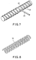
- A preferred process according to this invention for manufacturing the fiber reinforced resin coil spring is as follows. As shown in Fig.5, two kinds of
prepregs prepregs prepregs flexible mandrel 18 as shown in Fig.6 . By this process, acylindrical cord 20 is obtained. Thecord 20 is then wound on aspiral groove 23 formed on the peripheral surface of acolumnar die 22 as shown in Fig. 7, thecord 20 is fixed, and the resin is cured by heat. The cord is then removed from the die so as to obtain thecoil spring 10 as shown in Fig. 8. - A flexible mandrel is used as shown in Fig. 6. Suitable materials for the mandrel are Nylon, silicone resin, Teflon and polymethylpentene. From the viewpoint of handling properties and thermal stability, polymethylpentene is preferred. As these materials are lighter than metals, it is not necessary to form a hollow to decrease weight, and it is therefore possible to use a
cord 20 wherein themandrel 18 has been left inside. A coil spring made of such solid cords has high buckling strength. - To improve the impact resistance characteristics of the surface of the
coil spring 10, and to improve its molding properties and surface design, the outermost layer of the material may be made of fabric prepreg. - The above and other objects, features and advantages of the invention will be apparent from the following description of illustrative examples, which are to be read in connection with the accompanying drawings.
- Fig.1 is a partial front view of a coil spring subject to a compressive force.
- Fig.2 is a partial front view of a coil spring subject to a tensile force.
- Fig.3 is a partially enlarged perspective view of a cord of the coil spring subject to a compressive force.
- Fig.4 is a partially enlarged perspective view of a cord of the coil spring subject to a tensile force.
- Fig.5 is an exploded perspective view of a prepreg for the cord.
- Fig.6 is an enlarged cross section of a cord made from a prepreg wound on a mandrel.
- Fig.7 is a perspective view of a die on the spiral groove of which the cord is wound.
- Fig.8 is a perspective view of a manufactured coil spring.
- Carbon fiber/ epoxy resin prepregs (manufactured by Toho Rayon Co. Ltd.) in which all the carbon fibers are uniformly orientated in one direction were prepared. A prepreg sheet was then obtained by laminating the prepregs so that the carbon fibers of the first group of prepregs and those of the second group of prepregs crossed each other at an angle of ±45° , and the amount ratio A/B of the plus direction fibers and the minus direction fibers was 1.39. A flexible mandrel, whereof the diameter was 8 mm and the length was 1000 mm, and which was made of polymethylpentene resin, was prepared. The above-mentioned prepreg sheet was wound on the mandrel in such a manner that the side edge of the sheet was parallel to the axis of the mandrel and the directions of the fibers of the prepregs were ±45° . A cord of diameter 17 mm was thereby obtained.
- The cord was wrapped by polyester tape and fixed on the spiral groove of the die. The cord was then heated, first for 30 minutes at a temperature of 80 ° C and then for 2 hours at a temperature of 130 ° C. The resin of the cord was thereby compressed by the shrinkage of the tape, and the resin was cured. The cured resin coil spring was then taken out of the groove of the die.
- By this process, a coil spring was obtained whereof the strand diameter was 16 mm, the mean diameter of spring was 75 mm, the free height was 120 mm, the number of effective winding turns was 2.5, and the amount ratio A/B was 1.39.
- A jig was fitted on the top of the coil spring for the purpose of carrying out a compressive test using an Instron type testing machine. In the test, a load was applied to the center axis of the coil spring. The result of the test shows that the corrected shearing strength was 57 kgf/mm ² .
-
- The amount ratio A/B of the fibers in the plus and minus direction was changed to 1.67 as shown in Table 1. The other conditions were the same as those of the first example. A coil spring was manufactured for the compressive test in the same manner as that of Example 1. According to the test results, the corrected shearing strength of the coil spring of this example was found to be 52 kgf/mm² .
- The amount ratio A/B of the fibers in the plus and minus directions was changed to 2.0. The other conditions were the same as those of the first example. A coil spring was manufactured for the compressive test in the same manner as that of Example 1. The resulting corrected shearing strength was 45 kgf/mm ² .
- The amount ratio A/B of the fibers in the plus and minus directions was set at 0.5. The other conditions were the same as those of Example 1. A coil spring was manufactured for the compressive test which was performed in the same manner as that of Example 1. According to the results of the compressive test, the corrected shearing strength was 38 kgf/mm² . This value is rather low in comparison to the values of Examples 1∼3.
- The amount ratio A/B of the fibers in the plus and minus directions was set at 1.0. The other conditions were the same as those of Example 1. A coil spring was manufactured and tested for compression in the same manner as that of the first example.
- According to the test results, the corrected shearing strength was 39 kgf/mm² as shown in Table 1. This value is substantially the same as that of comparative Example 1.
- All the carbon fibers were uniformly oriented in the plus direction at an angle of 45° , the amount ratio A/B of the fibers in the plus and minus directions being 0. A coil spring was manufactured in the same manner, the other conditions being the same as those of the first example. This coil spring was subjected to a compressive test as in the first example. The result of the test showed that the corrected shearing strength was 8 kgf/mm² ,which is a very low value.
- A bundle of high strength carbon fibers (Besfight, manufactured by Toho Rayon Co. Ltd.) was impregnated with bisphenol-A type epoxy resin containing hardener. The resin-impregnated bundle of carbon fibers was wound on a mandrel by the filament winding method in such a manner that the amount ratio A/B of the fibers in the plus and minus directions was 1.67, and the directions of the two groups of fibers was ±45° relative to the axis of the mandrel. A cord was thereby manufactured. This cord was molded by the same process as that used in the first example. The coil spring so manufactured was then subjected to a compressive test as in the first example. The result of the test showed that the corrected shearing strength of the spring was 53 kgf/mm² .
- A carbon fiber/ epoxy resin prepreg (manufactured by Toho Rayon Co. Ltd.) in which all the carbon fibers were uniformly oriented in one direction was used. A plurality of prepregs were laminated on each other in such a manner that the amount ratio A/B of the fibers in the plus and minus directions was 1.39, and the directions of the two groups of fibers was ±45° .
- The laminated sheet was wound on a mandrel in such a manner that the side edge of the sheet was parallel to the axis of the mandrel, and the directions of the reinforcing fibers were ±45° relative to the axis of the resulting cords. Another plain woven prepreg (manufactured by Toho Rayon Co. Ltd.) was wound on the outer surface so that the angles of the fibers were ±45° . In this way, a cord was obtained which was molded by the same process as that of the first example, resulting in a coil spring wherein the amount ratio A/B was 1.33.
- This coil spring had a smooth surface and novel design because of its outermost prepreg of fabric. The shearing strength of the coil spring was 56 kgf/mm² , which is a relatively high value.
- A coil spring, wherein the amount ratio A/B was 1.39 and whereof the shape and dimensions were the same as those of the coil spring of the first example, was manufactured. The coil spring was then subjected to a tensile test wherein a tensile force was applied to the coil spring. The corrected shearing strength was 43 kgf/mm² .
- The amount ratio A/B was set at 1.0, the other conditions being the same as those of the first example. A tension coil spring was thereby manufactured. This coil spring was subjected to a tensile test. The result of the test showed that the corrected shearing strength was 31 kgf/mm² .

Claims (6)
- A carbon fiber reinforced resin coil spring consisting of a spirally wound cord;
characterized in that the carbon fibers are oriented at an angle of ±30° ∼±60° relative to the axis of the cord; and
the ratio of the amounts of the carbon fibers A and B is
- A carbon fiber reinforced resin coil spring as defined in claim 1, wherein a carbon fiber fabric is arranged as the outermost layer of said cord.
- A method for manufacturing a carbon fiber reinforced resin coil spring, comprising:
a process for laminating a plurality of carbon fiber/ resin prepregs so that the direction of the carbon fibers in a first group of prepregs and that of the carbon fibers in a second group of prepregs intersect with each other, and the amount ratio A/B of the carbon fibers oriented in the direction compressive force is applied and the carbon fibers oriented in the direction tensile force is applied is
a process for fixing said cord on the spiral groove of a die; and
a process for curing the matrix resin of said prepreg by heating said cord under predetermined conditions for obtaining a spiral coil spring. - A method for manufacturing the carbon fiber reinforced resin coil spring according to claim 3, wherein said cord is manufactured from prepregs, the prepregs in the plus and minus directions are used as the first and second groups of prepregs respectively, and the area weight of fibers in the former group is varied from that of the latter for the purpose of regulating the amount ratio A/B.
- A method for manufacturing the carbon fiber reinforced resin coil spring according to the claim 3, wherein said cord is manufactured from prepregs, a prepreg oriented in a plus direction and a prepreg oriented in a minus direction are used, the weights of the fibers in the two groups of prepregs have the same area weight of fiber, and the ply number of prepregs in the plus direction is varied from the ply number of prepregs in the minus direction for the purpose of regulating the amount ratio A/B.
- A method for manufacturing a carbon fiber reinforced coil spring, comprising:
a process for winding a resin-impregnated bundle of carbon fibers on a mandrel in a first direction; and
a process for winding a resin impregnated bundle of carbon fibers on said mandrel in a second opposite direction;
the amount ratio A/B of the amount of carbon fibers oriented in the direction compressive force is applied and the amount of carbon fibers oriented in the direction tensile force is applied being regulated by the numbers of winding turns in said two directions.
Applications Claiming Priority (2)
| Application Number | Priority Date | Filing Date | Title |
|---|---|---|---|
| JP212368/93 | 1993-08-04 | ||
| JP5212368A JP3009311B2 (en) | 1993-08-04 | 1993-08-04 | Fiber-reinforced resin coil spring and method of manufacturing the same |
Publications (3)
| Publication Number | Publication Date |
|---|---|
| EP0637700A2 true EP0637700A2 (en) | 1995-02-08 |
| EP0637700A3 EP0637700A3 (en) | 1995-05-03 |
| EP0637700B1 EP0637700B1 (en) | 1999-05-12 |
Family
ID=16621407
Family Applications (1)
| Application Number | Title | Priority Date | Filing Date |
|---|---|---|---|
| EP94305779A Expired - Lifetime EP0637700B1 (en) | 1993-08-04 | 1994-08-04 | Carbon fiber reinforced resin coil spring and method for manufacturing the same |
Country Status (4)
| Country | Link |
|---|---|
| US (1) | US5685525A (en) |
| EP (1) | EP0637700B1 (en) |
| JP (1) | JP3009311B2 (en) |
| DE (1) | DE69418394T2 (en) |
Cited By (9)
| Publication number | Priority date | Publication date | Assignee | Title |
|---|---|---|---|---|
| EP0812673A2 (en) * | 1996-06-13 | 1997-12-17 | Fuji Jukogyo Kabushiki Kaisha | Cylindrical article made of fiber reinforced plastic material and method for its manufacture |
| EP1298347A3 (en) * | 2001-09-26 | 2004-07-21 | ArvinMeritor Technology, LLC | Torsion bar |
| WO2014014481A1 (en) * | 2012-07-18 | 2014-01-23 | Mssc Us | Composite coil spring |
| DE102014207151A1 (en) | 2014-04-14 | 2015-10-15 | Leichtbau-Zentrum Sachsen Gmbh | Torsionally loaded rod-shaped component |
| WO2015188963A1 (en) | 2014-06-11 | 2015-12-17 | Thyssenkrupp Ag | Torsion-loaded rod-shaped component with different fibre reinforcements for tensile and compressive loading |
| WO2018130561A1 (en) | 2017-01-10 | 2018-07-19 | Basf Se | Strand profile and method for producing a strand profile |
| WO2018199365A1 (en) * | 2017-04-28 | 2018-11-01 | 윈엔윈(주) | Method for manufacturing carbon fiber-reinforced composite material spring, and carbon fiber-reinforced composite material spring manufactured thereby |
| WO2019036801A1 (en) | 2017-08-24 | 2019-02-28 | Ressorts Liberte Inc. | Coil spring and method of fabrication thereof |
| WO2019219694A1 (en) | 2018-05-14 | 2019-11-21 | Basf Polyurethanes Gmbh | Method for producing a composite spring, and composite spring |
Families Citing this family (33)
| Publication number | Priority date | Publication date | Assignee | Title |
|---|---|---|---|---|
| US5988612A (en) * | 1997-08-07 | 1999-11-23 | Bertelson; Peter C. | Composite helical springs and process of manufacture |
| US6454251B1 (en) * | 2000-05-01 | 2002-09-24 | John C. Fish | Composite cord assembly |
| JP2002371461A (en) * | 2001-06-13 | 2002-12-26 | Tokai Univ | Ultra high strength carbon fiber and high strength carbon fiber-reinforced carbon composite material |
| DE10228406B4 (en) * | 2001-06-25 | 2016-09-15 | Bernhard Scheuring | Use of a composite component and method for producing the composite component used |
| US7591592B2 (en) * | 2002-08-12 | 2009-09-22 | Menza Limited | Journal |
| DE102004039504B4 (en) * | 2003-09-09 | 2017-05-11 | Man Truck & Bus Ag | Multi-part valve spring of a motor vehicle engine |
| US8505798B2 (en) | 2005-05-12 | 2013-08-13 | Stanley Fastening Systems, L.P. | Fastener driving device |
| WO2006124498A2 (en) * | 2005-05-12 | 2006-11-23 | Stanley Fastening Systems, L.P. | Fastener driving device |
| US20080048000A1 (en) * | 2006-05-31 | 2008-02-28 | David Simonelli | Fastener driving device |
| US20140148917A1 (en) * | 2012-11-27 | 2014-05-29 | Ronald Harry Nelson | Carbon fiber prosthetic foot with hollow cross sections |
| US20100116864A1 (en) * | 2008-11-07 | 2010-05-13 | Pneutools, Incorporated | Motorized fastener applicator |
| DE102011018217A1 (en) | 2010-04-19 | 2011-12-15 | Leichtbau-Zentrum Sachsen Gmbh | Method for manufacturing spring for insertion into undercarriage of vehicle, involves removing rod-shaped core element from spring element that is separated from molding tool, where core element is made of rubber material |
| JP5735826B2 (en) * | 2011-03-10 | 2015-06-17 | 日本発條株式会社 | Fiber reinforced plastic spring |
| CN202441794U (en) * | 2012-03-02 | 2012-09-19 | 喜临门家具股份有限公司 | Spiral pneumatic spring |
| JP5921295B2 (en) * | 2012-04-04 | 2016-05-24 | 株式会社シマノ | Blank and fishing rod |
| DE102012112939A1 (en) * | 2012-12-21 | 2014-06-26 | Leichtbau-Zentrum Sachsen Gmbh | Apparatus and method for infiltrating a fiber preform |
| US10240654B2 (en) * | 2013-04-03 | 2019-03-26 | Mubea Carbo Tech Gmbh | Hybrid spring device |
| US20150047224A1 (en) * | 2013-08-16 | 2015-02-19 | Jing Zhao | Shoe having carbon fiber composite spring soles and upper support |
| JP6358645B2 (en) * | 2013-10-31 | 2018-07-18 | 東洋炭素株式会社 | Coil spring |
| CA2833674A1 (en) * | 2013-11-15 | 2015-05-15 | Rem Enterprises Inc. | Method for coating an extension spring |
| JP5864647B2 (en) * | 2014-03-14 | 2016-02-17 | ミズノ テクニクス株式会社 | Fiber reinforced resin coil spring and method for manufacturing fiber reinforced resin coil spring |
| US9889633B2 (en) | 2014-04-10 | 2018-02-13 | Honda Motor Co., Ltd. | Attachment method for laminate structures |
| DE102014115619A1 (en) * | 2014-10-28 | 2016-04-28 | Dr. Ing. H.C. F. Porsche Aktiengesellschaft | Spiral spring and related manufacturing process |
| JP6502235B2 (en) | 2015-10-29 | 2019-04-17 | 日本発條株式会社 | Wire member for elastic member and elastic member |
| JP2017082967A (en) * | 2015-10-29 | 2017-05-18 | 日本発條株式会社 | Wire for coil spring and coil spring |
| JP2017081048A (en) * | 2015-10-29 | 2017-05-18 | 日本発條株式会社 | Wire rod for elastic member, and elastic member |
| JP6832338B2 (en) * | 2016-03-23 | 2021-02-24 | 日本発條株式会社 | Coil spring |
| JP6910211B2 (en) * | 2017-06-07 | 2021-07-28 | 株式会社Cfcデザイン | Carbon / carbon composite spring element and its manufacturing method |
| CN107285796B (en) * | 2017-07-21 | 2020-09-04 | 湖南金博碳素股份有限公司 | Carbon-based composite material spiral spring and production method thereof |
| DE102017218553B4 (en) * | 2017-10-18 | 2019-07-11 | Ford Global Technologies, Llc | Manufacturing process for leaf springs made of fiber-reinforced plastic with integrated eyebolts and leaf spring made of fiber-reinforced plastic |
| US11617670B2 (en) | 2018-01-10 | 2023-04-04 | Grd Innovations, Llc | Variable radius spring assembly |
| JP7092947B2 (en) * | 2019-07-01 | 2022-06-28 | 三菱製鋼株式会社 | Composite coil spring with carbon and fiberglass layers |
| CN110512155B (en) * | 2019-07-11 | 2020-06-26 | 江苏长龄液压股份有限公司 | Variable cross-section spring blank and processing tool and processing technology thereof |
Citations (6)
| Publication number | Priority date | Publication date | Assignee | Title |
|---|---|---|---|---|
| GB2041152A (en) * | 1979-01-15 | 1980-09-03 | Celanese Corp | Fibre/resin springs |
| GB2056615A (en) * | 1979-07-12 | 1981-03-18 | Exxon Research Engineering Co | Fiber-reinforced coil spring |
| JPS6044627A (en) * | 1983-08-22 | 1985-03-09 | Mitsubishi Rayon Co Ltd | Coiled spring |
| DE3506037C1 (en) * | 1985-02-21 | 1986-01-16 | Deutsche Forschungs- und Versuchsanstalt für Luft- und Raumfahrt e.V., 5300 Bonn | Coil spring and process for its manufacture |
| FR2602461A1 (en) * | 1984-05-17 | 1988-02-12 | Silvatrim Sa | Method for manufacturing helical springs made of composite materials |
| JPH01269736A (en) * | 1988-04-22 | 1989-10-27 | Mitsubishi Heavy Ind Ltd | Helical spring |
Family Cites Families (3)
| Publication number | Priority date | Publication date | Assignee | Title |
|---|---|---|---|---|
| US4380483A (en) * | 1979-01-15 | 1983-04-19 | Celanese Corporation | Process for forming improved carbon fiber reinforced composite coil spring |
| GB8316690D0 (en) * | 1983-06-20 | 1983-07-20 | Secretary Industry Brit | Springs of fibre-reinforced plastics material |
| JPS62215135A (en) * | 1986-03-12 | 1987-09-21 | Somar Corp | Fiber reinforced plastic bar shaped torsion spring |
-
1993
- 1993-08-04 JP JP5212368A patent/JP3009311B2/en not_active Expired - Fee Related
-
1994
- 1994-08-02 US US08/284,136 patent/US5685525A/en not_active Expired - Lifetime
- 1994-08-04 DE DE69418394T patent/DE69418394T2/en not_active Expired - Lifetime
- 1994-08-04 EP EP94305779A patent/EP0637700B1/en not_active Expired - Lifetime
Patent Citations (6)
| Publication number | Priority date | Publication date | Assignee | Title |
|---|---|---|---|---|
| GB2041152A (en) * | 1979-01-15 | 1980-09-03 | Celanese Corp | Fibre/resin springs |
| GB2056615A (en) * | 1979-07-12 | 1981-03-18 | Exxon Research Engineering Co | Fiber-reinforced coil spring |
| JPS6044627A (en) * | 1983-08-22 | 1985-03-09 | Mitsubishi Rayon Co Ltd | Coiled spring |
| FR2602461A1 (en) * | 1984-05-17 | 1988-02-12 | Silvatrim Sa | Method for manufacturing helical springs made of composite materials |
| DE3506037C1 (en) * | 1985-02-21 | 1986-01-16 | Deutsche Forschungs- und Versuchsanstalt für Luft- und Raumfahrt e.V., 5300 Bonn | Coil spring and process for its manufacture |
| JPH01269736A (en) * | 1988-04-22 | 1989-10-27 | Mitsubishi Heavy Ind Ltd | Helical spring |
Non-Patent Citations (2)
| Title |
|---|
| PATENT ABSTRACTS OF JAPAN vol. 14, no. 33 (M-923) (3976) 22 January 1990 & JP-A-01 269 736 (MITSUBISHI HEAVY IND) 27 October 1989 * |
| PATENT ABSTRACTS OF JAPAN vol. 9, no. 172 (M-397) (1895) 17 July 1985 & JP-A-60 044 627 (MITSUBISHI RAYON) 9 March 1985 * |
Cited By (28)
| Publication number | Priority date | Publication date | Assignee | Title |
|---|---|---|---|---|
| EP0812673A3 (en) * | 1996-06-13 | 1999-05-12 | Fuji Jukogyo Kabushiki Kaisha | Cylindrical article made of fiber reinforced plastic material and method for its manufacturing |
| EP0812673A2 (en) * | 1996-06-13 | 1997-12-17 | Fuji Jukogyo Kabushiki Kaisha | Cylindrical article made of fiber reinforced plastic material and method for its manufacture |
| EP1298347A3 (en) * | 2001-09-26 | 2004-07-21 | ArvinMeritor Technology, LLC | Torsion bar |
| US9982734B2 (en) | 2012-07-18 | 2018-05-29 | Mitsubishi Steel Mfg. Co., Ltd. | Composite coil spring |
| WO2014014481A1 (en) * | 2012-07-18 | 2014-01-23 | Mssc Us | Composite coil spring |
| CN104583637A (en) * | 2012-07-18 | 2015-04-29 | Mssc有限公司 | Composite coil spring |
| CN107255130B (en) * | 2012-07-18 | 2019-09-20 | 三菱制钢株式会社 | Compound disc spring |
| US10385940B2 (en) | 2012-07-18 | 2019-08-20 | Mssc Inc | Composite coil spring |
| EP3388708A1 (en) * | 2012-07-18 | 2018-10-17 | Mitsubishi Steel MFG. CO., LTD. | Composite coil spring |
| US9677637B2 (en) | 2012-07-18 | 2017-06-13 | Mitsubishi Steel Mfg. Co., Ltd. | Composite coil spring |
| CN104583637B (en) * | 2012-07-18 | 2017-07-25 | 三菱制钢株式会社 | Compound disc spring |
| CN107255130A (en) * | 2012-07-18 | 2017-10-17 | 三菱制钢株式会社 | Compound disc spring |
| RU2706507C1 (en) * | 2014-04-14 | 2019-11-19 | Тиссенкрупп Аг | Torsion spring and method of making torsion spring |
| DE102014207151A1 (en) | 2014-04-14 | 2015-10-15 | Leichtbau-Zentrum Sachsen Gmbh | Torsionally loaded rod-shaped component |
| US10323710B2 (en) | 2014-04-14 | 2019-06-18 | ThyssenKrupp Federn und Stabilisatoren GmbH | Bar-shaped component loaded in torsion |
| WO2015158661A1 (en) | 2014-04-14 | 2015-10-22 | Leichtbau-Zentrum Sachsen Gmbh | Bar-shaped component loaded in torsion |
| DE102014211096A1 (en) | 2014-06-11 | 2015-12-17 | Thyssenkrupp Ag | Torsionally loaded rod-shaped component with different fiber reinforcements for tensile and compressive loads |
| RU2671423C2 (en) * | 2014-06-11 | 2018-10-31 | Тиссенкрупп Аг | Torsion-loaded rod-shaped component with different fibre reinforcements for tensile and compressive loading |
| US11078979B2 (en) | 2014-06-11 | 2021-08-03 | ThyssenKrupp Federn und Stabilisatoren GmbH | Torsion-loaded rod-shaped component with different fibre reinforcements for tensile and compressive loading |
| WO2015188963A1 (en) | 2014-06-11 | 2015-12-17 | Thyssenkrupp Ag | Torsion-loaded rod-shaped component with different fibre reinforcements for tensile and compressive loading |
| WO2018130561A1 (en) | 2017-01-10 | 2018-07-19 | Basf Se | Strand profile and method for producing a strand profile |
| WO2018199365A1 (en) * | 2017-04-28 | 2018-11-01 | 윈엔윈(주) | Method for manufacturing carbon fiber-reinforced composite material spring, and carbon fiber-reinforced composite material spring manufactured thereby |
| CN111465778A (en) * | 2017-08-24 | 2020-07-28 | 瑞索兹丽伯特有限公司 | Coil spring and method for manufacturing same |
| EP3673184A4 (en) * | 2017-08-24 | 2021-05-05 | Ressorts Liberte Inc. | Coil spring and method of fabrication thereof |
| WO2019036801A1 (en) | 2017-08-24 | 2019-02-28 | Ressorts Liberte Inc. | Coil spring and method of fabrication thereof |
| US11248674B2 (en) | 2017-08-24 | 2022-02-15 | Ressorts Liberte Inc. | Coil spring and method of fabrication thereof |
| CN111465778B (en) * | 2017-08-24 | 2022-05-31 | 瑞索兹丽伯特有限公司 | Coil spring and method for manufacturing same |
| WO2019219694A1 (en) | 2018-05-14 | 2019-11-21 | Basf Polyurethanes Gmbh | Method for producing a composite spring, and composite spring |
Also Published As
| Publication number | Publication date |
|---|---|
| DE69418394D1 (en) | 1999-06-17 |
| EP0637700B1 (en) | 1999-05-12 |
| JP3009311B2 (en) | 2000-02-14 |
| DE69418394T2 (en) | 1999-09-30 |
| US5685525A (en) | 1997-11-11 |
| JPH0742778A (en) | 1995-02-10 |
| EP0637700A3 (en) | 1995-05-03 |
Similar Documents
| Publication | Publication Date | Title |
|---|---|---|
| EP0637700B1 (en) | Carbon fiber reinforced resin coil spring and method for manufacturing the same | |
| US3900357A (en) | Composite material springs and manufacture | |
| US5580626A (en) | High strength, high stiffness, curved composite member | |
| US4528051A (en) | Fiber reinforced component and method for strengthening such components | |
| CA2139692C (en) | Composite shaft structure and manufacture | |
| US6612556B2 (en) | Multihelical composite spring | |
| US4260143A (en) | Carbon fiber reinforced composite coil spring | |
| US5512119A (en) | Method of making a hybrid prepreg | |
| EP0541795B1 (en) | New prepreg and composite molding, and production of composite molding | |
| US4380483A (en) | Process for forming improved carbon fiber reinforced composite coil spring | |
| US3449199A (en) | Helical reinforced materials and method of making same | |
| EP0733469A2 (en) | Composite structural member with high bending strength and method of manufacture | |
| US5981025A (en) | Composite structure | |
| US6592979B1 (en) | Hybrid matrix fiber composites | |
| AU710029B2 (en) | External fixation device | |
| US6270426B1 (en) | Golf club shaft | |
| US4753835A (en) | FRP plate and process for manufacturing the same | |
| GB2055449A (en) | Fibre reinforced pin | |
| JP3771360B2 (en) | Tubular body made of fiber reinforced composite material | |
| US5753324A (en) | Fiber-reinforced composite cylindrical form | |
| US4867091A (en) | Surfing boom | |
| JPH07144371A (en) | Carbon fiber reinforced resin composite material having high damping capacity | |
| US20190366617A1 (en) | Strand profile and process for producing a strand profile | |
| JPH07108620A (en) | Coiled spring molds | |
| JP2007064389A (en) | Coil spring made of fiber-reinforced resin, and its manufacturing method |
Legal Events
| Date | Code | Title | Description |
|---|---|---|---|
| PUAI | Public reference made under article 153(3) epc to a published international application that has entered the european phase |
Free format text: ORIGINAL CODE: 0009012 |
|
| AK | Designated contracting states |
Kind code of ref document: A2 Designated state(s): DE FR GB IT |
|
| RAX | Requested extension states of the european patent have changed |
Free format text: LT;SI |
|
| PUAL | Search report despatched |
Free format text: ORIGINAL CODE: 0009013 |
|
| AK | Designated contracting states |
Kind code of ref document: A3 Designated state(s): AT BE CH DE DK ES FR GB GR IE IT LI LU MC NL PT SE |
|
| RBV | Designated contracting states (corrected) |
Designated state(s): DE FR GB IT |
|
| 17P | Request for examination filed |
Effective date: 19951010 |
|
| GRAG | Despatch of communication of intention to grant |
Free format text: ORIGINAL CODE: EPIDOS AGRA |
|
| 17Q | First examination report despatched |
Effective date: 19970227 |
|
| GRAG | Despatch of communication of intention to grant |
Free format text: ORIGINAL CODE: EPIDOS AGRA |
|
| GRAG | Despatch of communication of intention to grant |
Free format text: ORIGINAL CODE: EPIDOS AGRA |
|
| GRAG | Despatch of communication of intention to grant |
Free format text: ORIGINAL CODE: EPIDOS AGRA |
|
| GRAH | Despatch of communication of intention to grant a patent |
Free format text: ORIGINAL CODE: EPIDOS IGRA |
|
| GRAH | Despatch of communication of intention to grant a patent |
Free format text: ORIGINAL CODE: EPIDOS IGRA |
|
| GRAA | (expected) grant |
Free format text: ORIGINAL CODE: 0009210 |
|
| AK | Designated contracting states |
Kind code of ref document: B1 Designated state(s): DE FR GB IT |
|
| REF | Corresponds to: |
Ref document number: 69418394 Country of ref document: DE Date of ref document: 19990617 |
|
| ET | Fr: translation filed | ||
| PLBE | No opposition filed within time limit |
Free format text: ORIGINAL CODE: 0009261 |
|
| STAA | Information on the status of an ep patent application or granted ep patent |
Free format text: STATUS: NO OPPOSITION FILED WITHIN TIME LIMIT |
|
| 26N | No opposition filed | ||
| REG | Reference to a national code |
Ref country code: GB Ref legal event code: IF02 |
|
| PGFP | Annual fee paid to national office [announced via postgrant information from national office to epo] |
Ref country code: IT Payment date: 20100803 Year of fee payment: 17 Ref country code: FR Payment date: 20100812 Year of fee payment: 17 |
|
| PGFP | Annual fee paid to national office [announced via postgrant information from national office to epo] |
Ref country code: GB Payment date: 20100819 Year of fee payment: 17 |
|
| PGFP | Annual fee paid to national office [announced via postgrant information from national office to epo] |
Ref country code: DE Payment date: 20110727 Year of fee payment: 18 |
|
| GBPC | Gb: european patent ceased through non-payment of renewal fee |
Effective date: 20110804 |
|
| REG | Reference to a national code |
Ref country code: FR Ref legal event code: ST Effective date: 20120430 |
|
| PG25 | Lapsed in a contracting state [announced via postgrant information from national office to epo] |
Ref country code: IT Free format text: LAPSE BECAUSE OF NON-PAYMENT OF DUE FEES Effective date: 20110804 |
|
| PG25 | Lapsed in a contracting state [announced via postgrant information from national office to epo] |
Ref country code: FR Free format text: LAPSE BECAUSE OF NON-PAYMENT OF DUE FEES Effective date: 20110831 Ref country code: GB Free format text: LAPSE BECAUSE OF NON-PAYMENT OF DUE FEES Effective date: 20110804 |
|
| PG25 | Lapsed in a contracting state [announced via postgrant information from national office to epo] |
Ref country code: DE Free format text: LAPSE BECAUSE OF NON-PAYMENT OF DUE FEES Effective date: 20130301 |
|
| REG | Reference to a national code |
Ref country code: DE Ref legal event code: R119 Ref document number: 69418394 Country of ref document: DE Effective date: 20130301 |