EP0637696B1 - Verfahren zur Herstellung von Paddel- und Schaftmontagen für Doppelschraubemisch und/oder Bearbeitungsvorrichtung und daraus resultierender Apparat - Google Patents
Verfahren zur Herstellung von Paddel- und Schaftmontagen für Doppelschraubemisch und/oder Bearbeitungsvorrichtung und daraus resultierender Apparat Download PDFInfo
- Publication number
- EP0637696B1 EP0637696B1 EP94101669A EP94101669A EP0637696B1 EP 0637696 B1 EP0637696 B1 EP 0637696B1 EP 94101669 A EP94101669 A EP 94101669A EP 94101669 A EP94101669 A EP 94101669A EP 0637696 B1 EP0637696 B1 EP 0637696B1
- Authority
- EP
- European Patent Office
- Prior art keywords
- shaft
- lobular
- projections
- root recesses
- lobular projections
- Prior art date
- Legal status (The legal status is an assumption and is not a legal conclusion. Google has not performed a legal analysis and makes no representation as to the accuracy of the status listed.)
- Expired - Lifetime
Links
- 238000000034 method Methods 0.000 title claims description 11
- 230000000712 assembly Effects 0.000 title claims description 7
- 238000000429 assembly Methods 0.000 title claims description 7
- 230000002093 peripheral effect Effects 0.000 claims description 20
- 239000000463 material Substances 0.000 claims description 11
- 230000002829 reductive effect Effects 0.000 claims description 3
- 238000004519 manufacturing process Methods 0.000 description 6
- 230000003247 decreasing effect Effects 0.000 description 4
- 230000005540 biological transmission Effects 0.000 description 3
- 230000013011 mating Effects 0.000 description 3
- 238000012545 processing Methods 0.000 description 3
- 238000012360 testing method Methods 0.000 description 3
- 230000015572 biosynthetic process Effects 0.000 description 2
- 238000012546 transfer Methods 0.000 description 2
- 238000013329 compounding Methods 0.000 description 1
- 230000007423 decrease Effects 0.000 description 1
- 230000001419 dependent effect Effects 0.000 description 1
- 238000013461 design Methods 0.000 description 1
- 230000000694 effects Effects 0.000 description 1
- 229910000078 germane Inorganic materials 0.000 description 1
- 230000002401 inhibitory effect Effects 0.000 description 1
- 229920003023 plastic Polymers 0.000 description 1
- 239000004033 plastic Substances 0.000 description 1
- 230000002028 premature Effects 0.000 description 1
- 230000008569 process Effects 0.000 description 1
- 230000009467 reduction Effects 0.000 description 1
- 230000000717 retained effect Effects 0.000 description 1
- 230000007480 spreading Effects 0.000 description 1
- 238000003892 spreading Methods 0.000 description 1
Images



Classifications
-
- B—PERFORMING OPERATIONS; TRANSPORTING
- B29—WORKING OF PLASTICS; WORKING OF SUBSTANCES IN A PLASTIC STATE IN GENERAL
- B29B—PREPARATION OR PRETREATMENT OF THE MATERIAL TO BE SHAPED; MAKING GRANULES OR PREFORMS; RECOVERY OF PLASTICS OR OTHER CONSTITUENTS OF WASTE MATERIAL CONTAINING PLASTICS
- B29B7/00—Mixing; Kneading
- B29B7/30—Mixing; Kneading continuous, with mechanical mixing or kneading devices
- B29B7/34—Mixing; Kneading continuous, with mechanical mixing or kneading devices with movable mixing or kneading devices
- B29B7/38—Mixing; Kneading continuous, with mechanical mixing or kneading devices with movable mixing or kneading devices rotary
- B29B7/46—Mixing; Kneading continuous, with mechanical mixing or kneading devices with movable mixing or kneading devices rotary with more than one shaft
- B29B7/48—Mixing; Kneading continuous, with mechanical mixing or kneading devices with movable mixing or kneading devices rotary with more than one shaft with intermeshing devices, e.g. screws
- B29B7/482—Mixing; Kneading continuous, with mechanical mixing or kneading devices with movable mixing or kneading devices rotary with more than one shaft with intermeshing devices, e.g. screws provided with screw parts in addition to other mixing parts, e.g. paddles, gears, discs
- B29B7/483—Mixing; Kneading continuous, with mechanical mixing or kneading devices with movable mixing or kneading devices rotary with more than one shaft with intermeshing devices, e.g. screws provided with screw parts in addition to other mixing parts, e.g. paddles, gears, discs the other mixing parts being discs perpendicular to the screw axis
-
- B—PERFORMING OPERATIONS; TRANSPORTING
- B29—WORKING OF PLASTICS; WORKING OF SUBSTANCES IN A PLASTIC STATE IN GENERAL
- B29B—PREPARATION OR PRETREATMENT OF THE MATERIAL TO BE SHAPED; MAKING GRANULES OR PREFORMS; RECOVERY OF PLASTICS OR OTHER CONSTITUENTS OF WASTE MATERIAL CONTAINING PLASTICS
- B29B7/00—Mixing; Kneading
- B29B7/30—Mixing; Kneading continuous, with mechanical mixing or kneading devices
- B29B7/34—Mixing; Kneading continuous, with mechanical mixing or kneading devices with movable mixing or kneading devices
- B29B7/38—Mixing; Kneading continuous, with mechanical mixing or kneading devices with movable mixing or kneading devices rotary
- B29B7/46—Mixing; Kneading continuous, with mechanical mixing or kneading devices with movable mixing or kneading devices rotary with more than one shaft
- B29B7/48—Mixing; Kneading continuous, with mechanical mixing or kneading devices with movable mixing or kneading devices rotary with more than one shaft with intermeshing devices, e.g. screws
- B29B7/488—Parts, e.g. casings, sealings; Accessories, e.g. flow controlling or throttling devices
- B29B7/489—Screws
-
- B—PERFORMING OPERATIONS; TRANSPORTING
- B29—WORKING OF PLASTICS; WORKING OF SUBSTANCES IN A PLASTIC STATE IN GENERAL
- B29C—SHAPING OR JOINING OF PLASTICS; SHAPING OF MATERIAL IN A PLASTIC STATE, NOT OTHERWISE PROVIDED FOR; AFTER-TREATMENT OF THE SHAPED PRODUCTS, e.g. REPAIRING
- B29C48/00—Extrusion moulding, i.e. expressing the moulding material through a die or nozzle which imparts the desired form; Apparatus therefor
- B29C48/25—Component parts, details or accessories; Auxiliary operations
- B29C48/36—Means for plasticising or homogenising the moulding material or forcing it through the nozzle or die
- B29C48/395—Means for plasticising or homogenising the moulding material or forcing it through the nozzle or die using screws surrounded by a cooperating barrel, e.g. single screw extruders
- B29C48/40—Means for plasticising or homogenising the moulding material or forcing it through the nozzle or die using screws surrounded by a cooperating barrel, e.g. single screw extruders using two or more parallel screws or at least two parallel non-intermeshing screws, e.g. twin screw extruders
-
- B—PERFORMING OPERATIONS; TRANSPORTING
- B29—WORKING OF PLASTICS; WORKING OF SUBSTANCES IN A PLASTIC STATE IN GENERAL
- B29C—SHAPING OR JOINING OF PLASTICS; SHAPING OF MATERIAL IN A PLASTIC STATE, NOT OTHERWISE PROVIDED FOR; AFTER-TREATMENT OF THE SHAPED PRODUCTS, e.g. REPAIRING
- B29C48/00—Extrusion moulding, i.e. expressing the moulding material through a die or nozzle which imparts the desired form; Apparatus therefor
- B29C48/25—Component parts, details or accessories; Auxiliary operations
- B29C48/36—Means for plasticising or homogenising the moulding material or forcing it through the nozzle or die
- B29C48/395—Means for plasticising or homogenising the moulding material or forcing it through the nozzle or die using screws surrounded by a cooperating barrel, e.g. single screw extruders
- B29C48/40—Means for plasticising or homogenising the moulding material or forcing it through the nozzle or die using screws surrounded by a cooperating barrel, e.g. single screw extruders using two or more parallel screws or at least two parallel non-intermeshing screws, e.g. twin screw extruders
- B29C48/405—Intermeshing co-rotating screws
-
- B—PERFORMING OPERATIONS; TRANSPORTING
- B29—WORKING OF PLASTICS; WORKING OF SUBSTANCES IN A PLASTIC STATE IN GENERAL
- B29C—SHAPING OR JOINING OF PLASTICS; SHAPING OF MATERIAL IN A PLASTIC STATE, NOT OTHERWISE PROVIDED FOR; AFTER-TREATMENT OF THE SHAPED PRODUCTS, e.g. REPAIRING
- B29C48/00—Extrusion moulding, i.e. expressing the moulding material through a die or nozzle which imparts the desired form; Apparatus therefor
- B29C48/25—Component parts, details or accessories; Auxiliary operations
- B29C48/36—Means for plasticising or homogenising the moulding material or forcing it through the nozzle or die
- B29C48/50—Details of extruders
- B29C48/505—Screws
- B29C48/57—Screws provided with kneading disc-like elements, e.g. with oval-shaped elements
-
- F—MECHANICAL ENGINEERING; LIGHTING; HEATING; WEAPONS; BLASTING
- F16—ENGINEERING ELEMENTS AND UNITS; GENERAL MEASURES FOR PRODUCING AND MAINTAINING EFFECTIVE FUNCTIONING OF MACHINES OR INSTALLATIONS; THERMAL INSULATION IN GENERAL
- F16D—COUPLINGS FOR TRANSMITTING ROTATION; CLUTCHES; BRAKES
- F16D1/00—Couplings for rigidly connecting two coaxial shafts or other movable machine elements
- F16D1/10—Quick-acting couplings in which the parts are connected by simply bringing them together axially
-
- F—MECHANICAL ENGINEERING; LIGHTING; HEATING; WEAPONS; BLASTING
- F16—ENGINEERING ELEMENTS AND UNITS; GENERAL MEASURES FOR PRODUCING AND MAINTAINING EFFECTIVE FUNCTIONING OF MACHINES OR INSTALLATIONS; THERMAL INSULATION IN GENERAL
- F16D—COUPLINGS FOR TRANSMITTING ROTATION; CLUTCHES; BRAKES
- F16D1/00—Couplings for rigidly connecting two coaxial shafts or other movable machine elements
- F16D1/10—Quick-acting couplings in which the parts are connected by simply bringing them together axially
- F16D2001/103—Quick-acting couplings in which the parts are connected by simply bringing them together axially the torque is transmitted via splined connections
-
- Y—GENERAL TAGGING OF NEW TECHNOLOGICAL DEVELOPMENTS; GENERAL TAGGING OF CROSS-SECTIONAL TECHNOLOGIES SPANNING OVER SEVERAL SECTIONS OF THE IPC; TECHNICAL SUBJECTS COVERED BY FORMER USPC CROSS-REFERENCE ART COLLECTIONS [XRACs] AND DIGESTS
- Y10—TECHNICAL SUBJECTS COVERED BY FORMER USPC
- Y10T—TECHNICAL SUBJECTS COVERED BY FORMER US CLASSIFICATION
- Y10T29/00—Metal working
- Y10T29/49—Method of mechanical manufacture
- Y10T29/49826—Assembling or joining
- Y10T29/49945—Assembling or joining by driven force fit
Definitions
- the invention relates to a method of constructing or reconstructing drive assemblies according to claim 1 and to a drive assembly having a shaft and an element in driving interrelationship therewith according to claim 6.
- the present invention especially refers to twin screw mixers, extruders or processors and, more particularly, to new and useful improvements in methods of making the paddle shaft assemblies which are employed to enable increases in the mixing power obtained without consequent reduction of the free volume in the twin screw mixer or compounder which would limit the volume of throughput material proceeding through such continuously operating machines.
- the present invention has been developed for use in twin screw mixing-compounding machines of the type used in the plastics industry, for example, and illustrated in the present assignee's prior patents US 3,195,868 and US 4,826,323.
- the larger machines of this type utilize preferably hydraulic motor-driven shafts with radially mating co-wiping, individual paddles, or worm sections thereon, both of which, hereinafter, are to be included within the term "paddle", as used hereinafter.
- the shafts which mount the paddles must be rotated at the same speed, and in the same direction of rotation, in order for the paddles to completely co-wipe one another, and, at the same time, completely wipe the interior of the barrel bore in which they are operative.
- the geometry of the surface of one of the paddle components must be generated by the mating paddle component for co-wiping to occur, and these geometric forms are a direct function of barrel bore diameter to shaft center-to-center distance.
- barrel bore diameter to shaft center-to-center distance.
- the paddle component wall thickness accordingly, increases in relationship to the increased shaft diameter and, with thicker paddle elements, the open volume of the machine for the same bore diameter is significantly decreased.
- present day machines which are to produce an increased rate of processing product cannot tolerate the power increases which are necessary for processing the materials.
- the present invention is concerned with the supply of greater power at lower stress levels to the mixer paddles in given size mixer barrels which presently employ the involute spline shafts which are, at this time, the state of the art in this field.
- the method and apparatus of the present invention employs a series of lobes, alternating with root recesses to which they tangentially join, as a configuration for the internal bores of the mixer paddles. These match the lobes and root recesses provided on the exterior periphery of the mixer shafts.
- increased power can be generated. Since much processing in such processors is horsepower hour per pound dependent, more material can be moved through the processor with the increased horsepower to process it.
- One of the prime objects of the present invention is to increase the power which is supplied, without decreasing the free volume of the mixer and inhibiting the throughput of material.
- a further object of the invention is to promote the use of more reliable equipment which does not risk the imposition of higher load stresses, and potential unreliable equipment operation with consequent premature failure rates.
- a further object of the invention is to provide a twin screw mixer having a paddle and shaft assembly wherein the lobular configuration to be described effects decreases in the shear stresses imposed at certain critical paddle locations, even though stresses increase at other locations to provide, however, a decreased stress ratio, taking into account assembly fit and practical manufacturing tolerances.
- Still another object of the invention is to provide higher strength shaft and paddle assemblies, with lower overall stresses involved in the power transfer, through use of an optimum number of novel lobes and lobular root recesses for the configuration.
- Still a further object of the invention is to provide an assembly which permits the transmission of higher torques than heretofore possible, with mixers of the same size.
- Still another object of the invention is to design a system of the character disclosed wherein the paddles have adequate hoop strength to accept and transmit the increased torque received, without spreading to interfere with the operation of the paddles in their wiping relationship with the barrel walls.
- Figure 1 is a schematic, side elevational, partly sectional view through a twin screw mixer of the type disclosed in some of the present assignee's previous patents.
- Figure 2 is an enlarged, schematic, fragmentary, cross-sectional view, taken on the line 2-2 of Figure 1, disclosing an involute gear configuration for the paddle bores and shaft perimeters.
- Figure 3 is an enlarged, fragmentary, schematic, cross-sectional view of the present prior art paddle bore involute spline structure.
- Figure 4 is an enlarged cross-sectional view, similar to Figure 2 but disclosing a different, true sine wave, lobular configuration as disclosed e.g. in document DE-3 635 916.
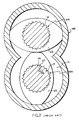
- Figure 5 is a schematic view, similar to Figure 2, of a shaft and paddle assembly of the present invention, utilized in a mixer barrel of much the same size as in Figure 2, and demonstrating the increased throughput volume which is available.
- Figure 6 is an enlarged, cross-sectional, elevational view of one of the preferred paddles and shafts only, wherein the lobe and root corner radii ratio is five to one;
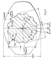
- Figure 7 is an enlarged fragmentary, cross-sectional, elevational view of another embodiment, with tangentially mating corner radii utilized on a three-to-one scale.
- a mixer-processor generally designated M, is shown as comprising a base 10 on which uprights 10a support a mixing barrel generally designated MB.
- the mixing barrel MB as Figure 2 particularly indicates, is of Figure-8-configuration and provides a Figure-8-shaped mixing chamber 11 within which twin mixing shafts 12 and 13 are revolved.
- paddles Fixed on the shafts 12 and 13, are paddles in the form of co-wiping screws or worms 20 and 21. Also provided as paddles, and fixed to the shafts 12 and 13, are co-wiping elements 22 and 23 which may be of the lenticular configuration disclosed in Figure 2. It is to be understood that the pairs of radially co-wiping members 22 and 23 are displaced angularly from one another to provide a successive helical formation, and that a cross section through the elements 20 and 21 would provide the lenticular configuration disclosed in Figure 2.
- the shafts 12 and 13 have an involute gear external configuration which mates with an involute gear configuration provided in the bores of paddles 22 and 23.
- These involute configurations comprise teeth 24 and roots 25 provided on the shafts 12 and 13 and intermeshed teeth 26 and roots 27 provided in the bore configurations, generally designated BR, of the paddle sections 20 and 21, and 22 and 23.
- the involute teeth 24 and 26 provided on the shaft and paddle bore configurations, respectively include convex side walls 28 on the teeth 24 and concave side walls 29 on the teeth 26.
- the convex walls 28 connect the outer peripheral surfaces 30 of the teeth 24 with the inner peripheral surfaces 31 or roots of the involute configurations, surfaces 30 and 31 being taken on radii extending from the shaft center c.
- the concave surfaces 29 connect the peripheral surfaces 32 of teeth 26 with the root surfaces 33 provided in each paddle bore configuration.
- the surfaces 32 and 33 match the surfaces 31 and 30 respectively, as indicated in Figure 3, with the exception there is a minor sliding clearance involved between them for manufacturing and assembly purposes.
- each of the paddles 22 and 23 is shown as having twelve alternating element lobular projections and element root recesses, generally designated 38 and 39, respectively.
- the intermediate peripheral surface portions 39a of the element root recesses 39 are taken on a radius 40 from the bore center 41.
- the shaft 12 includes matching shaft lobular projections 42 and shaft root recesses 43.
- each shaft root recess 43 includes an intermediate peripheral surface portion 43a taken on a radius 55 from shaft center 41 and it is to be noted that the radii 55 at the ends of each intermediate peripheral surface portion 43a subtend an angle of 7.5°.
- the element lobular projections 38 include matching intermediate peripheral surface portions 38a, subtending the same angle, as Figure 6 indicates.
- the arcuate corner portions 42b are taken on a radius of 0.376 mm (.0148 inches) about a point 44 located on a radius 54.
- the arcuate corner portions 38b are taken on radii of 1.88 mm (.0741 inches) from points 45 which are located to provide tangency between the portions 39b and 38a.
- the relationship between the radii which provide arcuate corner portions 42b and 38b is linear and in the preferred embodiment is five-to-one.
- matching the arcuate paddle bore surfaces 38b and the arcuate paddle corner surfaces 42b are shaft surfaces 43b and paddle surfaces 39b respectively.
- the paddle exterior surfaces include mid-surfaces 56 generated about radii 46 and arcuate portions 47 extending endwisely from surfaces 56 which are generated about radii 48 (taken from points 49) subtended by angles of 11.25° from the radius 46.
- the end surfaces 50 are taken on radii 51 from the center 41.
- the stress concentration for the involute convolution shown in Figures 2 and 3 was 12.48 kPa (1.81 psi) in tests which were conducted. For a twelve splined involute configuration it was higher at 14.55 kPa (2.11 psi). In contrast, the comparable stress concentration for the Figure 4 configuration was 9.45 kPa (1.37 psi). For the configuration using a tooth root radius to tip radius of three-to-one ( Figure 7), the stress concentration was 8.76 kPa (1.27 psi), and, when that tooth root radius-to tip radius ratio was five-to-one, the stress concentration had decreased to 8.48 kPa (1.23 psi).
- Applicants in the preferred embodiment of the invention disclosed in Figure 6, have greatly increased the size of the radius at the root of the lobe at point B to avoid a failure situation in which the shear stress at point B was such that yield strength in shear was exceeded.
- the hoop strength of the paddle elements 22 and 23 is also a consideration, and must be held within permissible values. In applicants' embodiments, sufficient material remains between the lobular projections of the shaft and the paddle wall portions 56 for the paddle to have sufficient hoop strength.
Landscapes
- Engineering & Computer Science (AREA)
- Mechanical Engineering (AREA)
- General Engineering & Computer Science (AREA)
- Processing And Handling Of Plastics And Other Materials For Molding In General (AREA)
- Mixers Of The Rotary Stirring Type (AREA)
Claims (13)
- Verfahren zur Herstellung oder Umrüstung von Antriebsanordnungen, enthaltend eine Welle (12, 13) und ein mit der Welle in Antriebsverbindung stehendes Element (22, 23), wobei das Verfahren die folgenden Verfahrensschritte umfaßt:a) Ausbilden des Elements (22, 23) mit einer Bohrung (BR), die abwechselnd zueinander angeordnete Elementvorsprünge (38) und Elementfußvertiefungen (39) aufweist, deren einander abwechselnde Umfangsflächenbereiche (38a, 39a) auf einem von der Achse (41) der Bohrung (BR) ausgehenden größeren bzw. kleineren Radius (40, 55) liegen,b) Ausbilden der Welle (12, 13) mit zu den Elementvorsprüngen und Elementfußvertiefungen komplementären und mit diesen in Eingriff kommenden Wellenvorsprüngen (42) und Wellenfußvertiefung (43) und Anbringen des Elements (22, 23) an der Welle in einer Weise, daß die Vorsprünge (38) und die Fußvertiefungen (39) des Elements (22, 23) mit den Fußvertiefungen (43) bzw. Vorsprüngen (34, 42) der Welle (12, 13) in Eingriffsverbindung kommen,c) Ausbilden der abwechselnd zueinander angeordneten Elementvorsprünge (38) und Elementfußvertiefungen (39) der Elementbohrung (BR) mit bogenförmigen Eckbereichen (38b, 39b), die zusammen die Oberflächen der Elementvorsprünge (38) mit denen der Elementfußvertiefungen (39) verbinden und ein Paar entgegengesetzt gebogener und tangential ineinander übergehender Eckbereiche (38b, 39b) bilden, die zudem tangential in die Umfangsflächenbereiche (38a, 39a) der Elementvorsprünge (38) bzw. Elementfußvertiefungen (39) übergehen;d) wobei durch die Ausbildung der bogenförmigen Eckbereiche (38b) der Elementvorsprünge (38) auf größeren Radien, die ein Vielfaches der Radien betragen, auf denen die gebogenen Eckbereiche (39b) der Elementfußvertiefungen (39) angeordnet sind, Belastungskonzentrationen verringert werdenf) und wobei die Wellenvorsprünge (42) und die Wellenfußvertiefungen (43) der Welle (12, 13) so gestaltet sind, daß sie mit den Elementfußvertiefungen (39) bzw. den Elementvorsprüngen (38) in Eingriff kommen können, wodurch sich eine komplementäre Eingriffsverbindung zwischen den Vorsprüngen (38, 42) und den Fußvertiefungen (39, 43) an der Welle (12, 13) bzw. der Elementbohrung (BR) ergibt.
- Verfahren nach Anspruch 1, wobei das Element als eine Schaufel (22, 23) für Mischer und Bearbeitungsvorrichtungen ausgebildet ist und auf parallelen Wellen (12, 13) radial fluchtende Schaufeln angeordnet sind, die mit derselben Geschwindigkeit und in derselben Drehrichtung umlaufen und jeweils sowohl einander als auch das Innere der Trommel (MB) des Mischers bzw. der Bearbeitungsvorrichtung abstreifen, die eine Mischkammer (11) aus miteinander verbundenen zylindrischen Bohrungen aufweist, in die nahe dem einem Ende (17) kontinuierlich Material aufgegeben und aus denen nahe dem anderen Ende (20a) kontinuierlich Material abgegeben wird,
gekennzeichnet durch die folgenden weiteren Verfahrensschritte:c) Vorsehen eines Paars von mit den Wellenvorsprüngen (42) und Wellenfußvertiefung (43) versehenen Wellen (12, 13),d) Ausbilden einer Vielzahl von die Elementvorsprünge (38) und die Elementfußvertiefungen (39) aufweisenden Schaufeln (22, 23),e) Anbringen einer Vielzahl dieser Schaufeln (22, 23) an den Wellen (12, 13), wobei die Elementvorsprünge (36, 38) bzw. die Elementfußvertiefungen (37, 39) der Schaufeln und die Wellenvorsprünge (42) bzw. die Wellenfußvertiefungen (43) der Wellen komplementär zueinander in Eingriffsverbindung stehen,f) Installieren der Wellen (12, 13) parallel und mit Abstand zueinander in der Mischkammer (11), wobei ihre Achsen zur Ausbildung eines bestimmten Mittenabstands zwischen ihnen einen bestimmten Abstand aufweisen, der ein vollständiges Abstreifen der Mischerkammer (MB) mit Hilfe der Schaufeln (22, 23) ermöglicht. - Verfahren nach Anspruch 1, wobei die Element- und Wellenvorsprünge (38, 42) und die Element- und Wellenfußvertiefung (39, 43) jeweils mittige Umfangsflächenbereiche (38a, 39a, 42a, 43a) zwischen den bogenförmigen Eckbereichen (38b, 39b, 42b, 43b) aufweisen, die jeweils auf vom Mittelpunkt (41) der Bohrung (BR) ausgehenden Radien (40, 55) angeordnet sind und tangential in die bogenförmigen Element- bzw. Welleneckbereiche übergehen, wobei die Bohrung (BR) an den Elementvorsprüngen (38) mittige Umfangsflächenbereiche (38a) aufweist, die eine größere Länge besitzen, als die mittigen Umfangsflächenbereiche (39a) an den Elementfußvertiefungen (39) der Bohrung, und wobei zwölf derartige Elementvorsprünge und zwölf derartige Elementfußvertiefungen vorgesehen sind.
- Verfahren nach Anspruch 1, wobei das Vielfache 3:1 beträgt.
- Verfahren nach Anspruch 1, wobei das Vielfache 5:1 beträgt.
- Antriebsanordnung, enthaltend eine Welle (12, 13) und ein mit der Welle in Antriebsverbindung stehendes Element (22, 23), wobeia) das Element (22, 23) mit einer Bohrung (BR) versehen ist, deren Achse (41) der Wellenachse entspricht, wobei die Bohrung so gestaltet ist, daß sie die Welle (12, 13) aufnehmen und dabei zu ihr in einer Antriebsbeziehung stehen kann,b) die Bohrung so gestaltet ist, daß sie einander abwechselnde Elementvorsprünge (38) und Elementfußvertiefungen (39) aufweist, die einander abwechselnde Umfangsflächenbereiche (38a, 39a) umfassen, welche auf einem von der Achse (41) der Bohrung (BR) ausgehenden größeren bzw. kleineren Radius (40, 55) liegen,c) die Welle (12, 13) komplementäre Wellenvorsprünge (42) und Wellenfußvertiefungen (43) aufweist, die von den Elementfußvertiefungen (39) bzw. den Elementvorsprüngen (38) der Bohrung (BR) aufgenommen werden und mit diesen in Eingriffsverbindung stehen,d) die abwechselnd angeordneten Elementvorsprünge (38) und Elementfußvertiefungen (39) bogenförmige Eckbereiche (38b, 39b) umfassen, welche zusammen die Flächen der Elementvorsprünge (38) und der Elementfußvertiefungen (39) miteinander verbinden und ein Paar entgegengesetzt gebogener, tangential ineinander übergehender Bogenflächen (38b, 39b) bilden, die zudem tangential in die Umfangsflächenbereiche (38a, 39a) der Elementvorsprünge (38) bzw. der Elementfußvertiefungen (39) übergehen, wobei die bogenförmigen Eckbereiche (38b) der Elementvorsprünge (36, 38) auf größeren Radien angesiedelt sind, die ein Vielfaches der Radien betragen, auf denen die bogenförmigen Eckbereiche (39b) der Elementfußvertiefungen liegen; unde) die Wellenvorsprünge (42) und Wellenfußvertiefung (43) komplementär zu den sich abwechselnden Elementfußvertiefungen (39) bzw. Elementvorsprüngen (38) gestaltet sind, so daß die Vorsprünge (38; 42) und die Fußvertiefungen (39; 43) auf der Welle (12, 13) bzw. an der Elementbohrung (BR) miteinander in komplementärer Eingriffsverbindung stehen.
- Anordnung nach Anspruch 6, wobei ein Wellenpaar (12, 13) vorgesehen und eine Vielzahl der als Schaufeln (22, 23) ausgebildeten Elemente an jeder der Wellen radial fluchtend gehaltert ist und wobei ein Antriebsmittel vorgesehen ist, um die Wellen mit gleicher Geschwindigkeit und in derselben Drehrichtung anzutreiben, wobei die Wellen und Schaufeln in einer Mischtrommel (MB) angeordnet sind, die durch mehrere zur axialen Aufnahme der Wellen dienende, miteinander verbundene, parallele, zylindrische Bohrungen gebildet wird.
- Anordnung nach Anspruch 6, wobei zwölf der genannten Elementvorsprünge (38) vorgesehen sind.
- Anordnung nach Anspruch 6, wobei die Elementvorsprünge (38) und die Elementfußvertiefungen (39) mittige Umfangsflächenbereiche (38a, 39a) aufweisen, die auf von der Achse (41) der Bohrung (BR) ausgehenden Radien (40, 55) angesiedelt sind, und wobei die Umfangsflächen der mittigen Flächenbereiche (38a) der Elementvorsprünge (38) wesentlich größer sind als die Umfangslängen der mittigen Flächenbereiche (39a) der Elementfußvertiefungen (39).
- Anordnung nach Anspruch 6, wobei die Anordnung als Doppelschraubenmischer bzw. Doppelschrauben-Bearbeitungsvorrichtung ausgebildet ist und eine Mischtrommel (BR) mit einem Materialeinlaß (17) an einem Ende und einem Materialauslaß (20a) am anderen Ende umfaßt und wobei die Anordnung die folgenden Bestandteile enthält:dadurch gekennzeichnet,a) ein Paar von Wellen (12, 13), die sich in Längsrichtung in der Trommel (MB) erstrecken;b) einen Mechanismus, der die Wellen (12, 13) mit der gleichen Geschwindigkeit in derselben Drehrichtung antreibt;c) wobei die Elemente durch Schaufeln (22, 23) gebildet werden, die mit Bohrungen (BR) versehen sind, deren Achsen (41) im wesentlichen den Wellenachsen entsprechen, wobei die Bohrungen so gestaltet sind, daß sie die Wellen (12, 13) aufnehmen und dabei mit ihnen in einer Antriebsbeziehung stehen können;d) daß die Schaufelbohrungen (BR) die einander abwechselnden Elementvorsprünge (38) und Elementfußvertiefungen (39) aufweisen und daß durch bogenförmige Eckbereiche (38b, 39b) gebildete bogenförmige Verbindungsbereiche die Elementvorsprünge und die Elementfußvertiefungen miteinander verbinden, wobei die bogenförmigen Verbindungsbereiche (38b) der Elementvorsprünge (38) tangential in die bogenförmigen Verbindungsbereiche (39b) der Elementfußvertiefungen (39) übergehen; unde) daß die Wellen (12, 13) mit komplementären Wellenvorsprüngen (42) und Wellenfußvertiefungen (43) versehen sind, die mit den Elementfußvertiefungen (39) bzw. den Elementvorsprüngen (38) der Schaufeln (22, 23) in Eingriff kommen.
- Anordnung nach Anspruch 10, wobei die bogenförmigen Eckbereiche (38b) der Elementvorsprünge (38) zur Verringerung der Belastungskonzentration an den Schaufeln (22, 23) auf größeren Radien angesiedelt sind, die ein Vielfaches der Radien betragen, auf denen die bogenförmigen Eckbereiche (39b) der Elementfußvertiefungen (39) liegen.
- Anordnung nach Anspruch 6, wobei das Vielfache 3 : 1 beträgt.
- Anordnung nach Anspruch 6 oder 11, wobei das Vielfache 5 : 1 beträgt.
Applications Claiming Priority (2)
| Application Number | Priority Date | Filing Date | Title |
|---|---|---|---|
| US08/098,134 US5304000A (en) | 1993-07-28 | 1993-07-28 | Methods of constructing paddle and shaft assemblies for twin screw mixer and/or processors and the resulting apparatus |
| US98134 | 1993-07-28 |
Publications (2)
| Publication Number | Publication Date |
|---|---|
| EP0637696A1 EP0637696A1 (de) | 1995-02-08 |
| EP0637696B1 true EP0637696B1 (de) | 2001-01-17 |
Family
ID=22267394
Family Applications (1)
| Application Number | Title | Priority Date | Filing Date |
|---|---|---|---|
| EP94101669A Expired - Lifetime EP0637696B1 (de) | 1993-07-28 | 1994-02-03 | Verfahren zur Herstellung von Paddel- und Schaftmontagen für Doppelschraubemisch und/oder Bearbeitungsvorrichtung und daraus resultierender Apparat |
Country Status (3)
| Country | Link |
|---|---|
| US (2) | US5304000A (de) |
| EP (1) | EP0637696B1 (de) |
| DE (1) | DE69426583T2 (de) |
Families Citing this family (17)
| Publication number | Priority date | Publication date | Assignee | Title |
|---|---|---|---|---|
| JP2834405B2 (ja) * | 1994-06-20 | 1998-12-09 | 株式会社神戸製鋼所 | 連続混練機 |
| US5520454A (en) * | 1994-09-09 | 1996-05-28 | Industrial Technology Research Institute | Injection screw set for an injection molding machine |
| US5932264A (en) * | 1997-10-07 | 1999-08-03 | General Mills, Inc. | Method for preparing cooked cereal dough using twin screw preconditioning extruder |
| DE19751730A1 (de) * | 1997-11-24 | 1999-05-27 | Bayer Ag | Mischvorrichtung |
| ATE274844T1 (de) * | 1998-04-09 | 2004-09-15 | Sdgi Holdings Inc | Wirbelkörper-distraktor |
| DE10112295B4 (de) * | 2001-03-08 | 2004-07-29 | Berstorff Gmbh | Herstellung eines Zylindergehäuses eines Doppelschneckenextruders |
| DE102004042746B4 (de) * | 2004-09-03 | 2008-03-27 | Leistritz Ag | Extruderschnecke |
| WO2006027096A1 (de) * | 2004-09-03 | 2006-03-16 | Leistritz Ag | Extruderschnecke, extruder sowie welle-nabe-verbindung |
| ATE468912T1 (de) * | 2005-04-18 | 2010-06-15 | Gea Pharma Systems Nv | Vorrichtung zur durchgehenden granulierung und verfahren zur durchgehenden granulierung von pulvermaterial |
| WO2007033328A2 (en) * | 2005-09-14 | 2007-03-22 | B & P Process Equipment And Systems, L.L.C. | Method and apparatus for forming a synthetic extrudate |
| US7806693B2 (en) * | 2007-04-23 | 2010-10-05 | Nobel Biocare Services Ag | Dental implant |
| US20080267003A1 (en) * | 2007-04-24 | 2008-10-30 | Shashank Gulabchand Kasliwal | Extrusion method and apparatus |
| DE102008029303A1 (de) * | 2008-06-20 | 2009-12-24 | Bayer Technology Services Gmbh | Schneckenelemente mit verbesserter Dispergierwirkung und geringem Energieeintrag |
| US8641263B2 (en) * | 2008-11-24 | 2014-02-04 | Kraft Foods Group Brands Llc | Method and apparatus for continuous processing of whole muscle meat products |
| US8308342B2 (en) * | 2008-11-24 | 2012-11-13 | Kraft Foods Global Brands Llc | Processing elements for mixing meat products |
| US8187651B2 (en) | 2008-11-24 | 2012-05-29 | Kraft Foods Global Brands Llc | Method and apparatus for continuous processing of whole muscle meat products |
| KR20210030460A (ko) * | 2018-08-30 | 2021-03-17 | 교세라 가부시키가이샤 | 회전 부재, 혼련기용 부재 및 그것을 사용한 혼련기, 베어링 및 그것을 사용한 베어링 유닛 |
Family Cites Families (16)
| Publication number | Priority date | Publication date | Assignee | Title |
|---|---|---|---|---|
| USRE20270E (en) * | 1937-02-16 | Spline shaft | ||
| US2668756A (en) * | 1948-09-27 | 1954-02-09 | Phillips Petroleum Co | Method of and apparatus for liquid-liquid contacting |
| US2777353A (en) * | 1952-10-30 | 1957-01-15 | Robert W Willis | Screw socket construction having tool guiding means formed therein |
| DE1264883B (de) * | 1965-12-15 | 1968-03-28 | Borg Warner | Axial verschiebbare, biegsame Wellenkupplung |
| US3584667A (en) * | 1966-09-19 | 1971-06-15 | Textron Inc | Coupling arrangement and tools for same |
| US3618902A (en) * | 1969-11-14 | 1971-11-09 | Teledyne Inc | Continuous mixer |
| DE2550969C2 (de) * | 1975-11-13 | 1982-12-16 | Josef 7120 Bietigheim Blach | Schneckenmaschine zum Homogenisieren von festen, flüssigen und zähviskosen Materialien |
| US4236833A (en) * | 1978-01-19 | 1980-12-02 | Blach Josef A | Screw machine for processing materials of solid, pasty and liquid consistency |
| US4269246A (en) * | 1979-05-10 | 1981-05-26 | Textron Inc. | Fastener and driver assembly |
| DE3030541C2 (de) * | 1980-08-13 | 1988-09-08 | Rudolf P. 7000 Stuttgart Fritsch | Vorrichtung zur kontinuierlichen Herstellung hochmolekularer Polymerer |
| US4357137A (en) * | 1980-08-18 | 1982-11-02 | Arinc Research Corporation | Shaft coupling |
| EP0220031B1 (de) * | 1985-10-16 | 1990-12-19 | Nippondenso Co., Ltd. | Schmiedeverfahren und -vorrichtung |
| DE3635916C1 (de) * | 1986-10-22 | 1988-03-24 | Voith Gmbh J M | Verzahnung fuer eine Wellen-Nabenverbindung |
| US4847963A (en) * | 1987-09-30 | 1989-07-18 | The Torrington Company | Camshaft manufacture |
| GB8804313D0 (en) * | 1988-02-24 | 1988-03-23 | Apv Plc | Improvements in/relating to mixers |
| US5171117A (en) * | 1991-10-16 | 1992-12-15 | Textron Inc. | Fastener with multilobular internal recess and tool entry ramps |
-
1993
- 1993-07-28 US US08/098,134 patent/US5304000A/en not_active Expired - Lifetime
-
1994
- 1994-01-31 US US08/189,180 patent/US5439286A/en not_active Expired - Lifetime
- 1994-02-03 EP EP94101669A patent/EP0637696B1/de not_active Expired - Lifetime
- 1994-02-03 DE DE69426583T patent/DE69426583T2/de not_active Expired - Lifetime
Also Published As
| Publication number | Publication date |
|---|---|
| US5304000A (en) | 1994-04-19 |
| EP0637696A1 (de) | 1995-02-08 |
| DE69426583T2 (de) | 2001-05-31 |
| US5439286A (en) | 1995-08-08 |
| DE69426583D1 (de) | 2001-02-22 |
Similar Documents
| Publication | Publication Date | Title |
|---|---|---|
| EP0637696B1 (de) | Verfahren zur Herstellung von Paddel- und Schaftmontagen für Doppelschraubemisch und/oder Bearbeitungsvorrichtung und daraus resultierender Apparat | |
| US4352568A (en) | Twin-screw machine with screws rotatable in the same direction | |
| US4261225A (en) | Step-down transmission for driving a plurality of extrusion screws | |
| US3565403A (en) | Continuous mixer | |
| US3423074A (en) | Multipurpose continuous mixing and/or kneading apparatus | |
| JP2648513B2 (ja) | 混合機械およびそれを操作する方法 | |
| US6170975B1 (en) | Multi-shaft extruder kneading discs, kneading disc blocks and extruder | |
| CN102834232B (zh) | 挤出机 | |
| EP0764074A1 (de) | Mehrschraubenextrusionsmengvorrichtung mit modularen mischelementen | |
| US20050084559A1 (en) | Extruder | |
| US4416544A (en) | Device for mixing, dispersing and homogenizing compounds with at least one viscous component | |
| RU2494866C2 (ru) | Редуктор экструдера | |
| US3734635A (en) | Shaft in particular screw shaft for feeding or kneading of raw material, by example synthetic material | |
| US8434928B2 (en) | Extruder having parallel shafts with combined elements | |
| KR20120055535A (ko) | 압출기 | |
| US20080019212A1 (en) | Extruder Screw, Extruder And Shaft-Hub Connection | |
| US20050152214A1 (en) | Device for dispersing and melting flowable materials | |
| EP2342481B1 (de) | Spannungskonzentrationsfreies keilverzahnungsprofil | |
| KR100671715B1 (ko) | 자체의 윙들 중 적어도 하나의 신장방향을 따라 가변하는 비틀림각을 가진 로터를 가지는 탄성중합체를 혼합하기 위한 내부 혼합기 | |
| JP3759968B2 (ja) | ミキサおよびプロセッサのための軸およびパドル組立体を構成する方法および軸およびパドル組立体 | |
| EP0087239B1 (de) | Kronrillen und Definition von deren Grundradius | |
| US5103689A (en) | Co-rotating dual outputs twin screw extruder with axial offset pinions | |
| US5092826A (en) | Arc gear having a rotary transmission of 1:1 | |
| CN100551673C (zh) | 挤出螺杆、挤出机和轴毂联接 | |
| US3923291A (en) | Internal mixer |
Legal Events
| Date | Code | Title | Description |
|---|---|---|---|
| PUAI | Public reference made under article 153(3) epc to a published international application that has entered the european phase |
Free format text: ORIGINAL CODE: 0009012 |
|
| AK | Designated contracting states |
Kind code of ref document: A1 Designated state(s): CH DE FR GB IT LI SE |
|
| 17P | Request for examination filed |
Effective date: 19950630 |
|
| 17Q | First examination report despatched |
Effective date: 19960506 |
|
| GRAG | Despatch of communication of intention to grant |
Free format text: ORIGINAL CODE: EPIDOS AGRA |
|
| GRAG | Despatch of communication of intention to grant |
Free format text: ORIGINAL CODE: EPIDOS AGRA |
|
| GRAH | Despatch of communication of intention to grant a patent |
Free format text: ORIGINAL CODE: EPIDOS IGRA |
|
| GRAH | Despatch of communication of intention to grant a patent |
Free format text: ORIGINAL CODE: EPIDOS IGRA |
|
| GRAA | (expected) grant |
Free format text: ORIGINAL CODE: 0009210 |
|
| AK | Designated contracting states |
Kind code of ref document: B1 Designated state(s): CH DE FR GB IT LI SE |
|
| ITF | It: translation for a ep patent filed | ||
| REG | Reference to a national code |
Ref country code: CH Ref legal event code: EP |
|
| REF | Corresponds to: |
Ref document number: 69426583 Country of ref document: DE Date of ref document: 20010222 |
|
| REG | Reference to a national code |
Ref country code: CH Ref legal event code: NV Representative=s name: AMMANN PATENTANWAELTE AG BERN |
|
| ET | Fr: translation filed | ||
| PLBE | No opposition filed within time limit |
Free format text: ORIGINAL CODE: 0009261 |
|
| STAA | Information on the status of an ep patent application or granted ep patent |
Free format text: STATUS: NO OPPOSITION FILED WITHIN TIME LIMIT |
|
| REG | Reference to a national code |
Ref country code: GB Ref legal event code: IF02 |
|
| 26N | No opposition filed | ||
| PGFP | Annual fee paid to national office [announced via postgrant information from national office to epo] |
Ref country code: SE Payment date: 20110225 Year of fee payment: 18 Ref country code: CH Payment date: 20110223 Year of fee payment: 18 Ref country code: DE Payment date: 20110225 Year of fee payment: 18 Ref country code: FR Payment date: 20110309 Year of fee payment: 18 Ref country code: IT Payment date: 20110225 Year of fee payment: 18 |
|
| PGFP | Annual fee paid to national office [announced via postgrant information from national office to epo] |
Ref country code: GB Payment date: 20110223 Year of fee payment: 18 |
|
| REG | Reference to a national code |
Ref country code: CH Ref legal event code: PL |
|
| GBPC | Gb: european patent ceased through non-payment of renewal fee |
Effective date: 20120203 |
|
| PG25 | Lapsed in a contracting state [announced via postgrant information from national office to epo] |
Ref country code: LI Free format text: LAPSE BECAUSE OF NON-PAYMENT OF DUE FEES Effective date: 20120229 Ref country code: CH Free format text: LAPSE BECAUSE OF NON-PAYMENT OF DUE FEES Effective date: 20120229 Ref country code: SE Free format text: LAPSE BECAUSE OF NON-PAYMENT OF DUE FEES Effective date: 20120204 |
|
| REG | Reference to a national code |
Ref country code: FR Ref legal event code: ST Effective date: 20121031 |
|
| PG25 | Lapsed in a contracting state [announced via postgrant information from national office to epo] |
Ref country code: IT Free format text: LAPSE BECAUSE OF NON-PAYMENT OF DUE FEES Effective date: 20120203 |
|
| REG | Reference to a national code |
Ref country code: DE Ref legal event code: R119 Ref document number: 69426583 Country of ref document: DE Effective date: 20120901 |
|
| PG25 | Lapsed in a contracting state [announced via postgrant information from national office to epo] |
Ref country code: GB Free format text: LAPSE BECAUSE OF NON-PAYMENT OF DUE FEES Effective date: 20120203 Ref country code: FR Free format text: LAPSE BECAUSE OF NON-PAYMENT OF DUE FEES Effective date: 20120229 |
|
| PG25 | Lapsed in a contracting state [announced via postgrant information from national office to epo] |
Ref country code: DE Free format text: LAPSE BECAUSE OF NON-PAYMENT OF DUE FEES Effective date: 20120901 |