EP0637464B1 - Resistance member adjusting mechanism of abrasive type grain whitening machines - Google Patents
Resistance member adjusting mechanism of abrasive type grain whitening machines Download PDFInfo
- Publication number
- EP0637464B1 EP0637464B1 EP94110137A EP94110137A EP0637464B1 EP 0637464 B1 EP0637464 B1 EP 0637464B1 EP 94110137 A EP94110137 A EP 94110137A EP 94110137 A EP94110137 A EP 94110137A EP 0637464 B1 EP0637464 B1 EP 0637464B1
- Authority
- EP
- European Patent Office
- Prior art keywords
- resistance
- roll assembly
- grain milling
- roll
- abrasive
- Prior art date
- Legal status (The legal status is an assumption and is not a legal conclusion. Google has not performed a legal analysis and makes no representation as to the accuracy of the status listed.)
- Expired - Lifetime
Links
Images


Classifications
-
- B—PERFORMING OPERATIONS; TRANSPORTING
- B02—CRUSHING, PULVERISING, OR DISINTEGRATING; PREPARATORY TREATMENT OF GRAIN FOR MILLING
- B02B—PREPARING GRAIN FOR MILLING; REFINING GRANULAR FRUIT TO COMMERCIAL PRODUCTS BY WORKING THE SURFACE
- B02B3/00—Hulling; Husking; Decorticating; Polishing; Removing the awns; Degerming
- B02B3/04—Hulling; Husking; Decorticating; Polishing; Removing the awns; Degerming by means of rollers
-
- B—PERFORMING OPERATIONS; TRANSPORTING
- B02—CRUSHING, PULVERISING, OR DISINTEGRATING; PREPARATORY TREATMENT OF GRAIN FOR MILLING
- B02B—PREPARING GRAIN FOR MILLING; REFINING GRANULAR FRUIT TO COMMERCIAL PRODUCTS BY WORKING THE SURFACE
- B02B7/00—Auxiliary devices
- B02B7/02—Feeding or discharging devices
Definitions
- the present invention refers to an abrasive type vertical grain milling machine comprising:
- Such an abrasive type vertical grain milling machine is known from CH-A-280080.
- the grains to be milled such as rice grains
- the grains are forcibly rotated in a circumferential direction by the grain milling roll assembly.
- the rice grains rub against each other and other surfaces thereof are scraped so that they are milled, or whitened. Rubbing between the rice grains becomes more intense as the amount of the projection of the resistance members is increased to impart a higher resistance to the movement of the rice grains in a circumferential direction, which results in the milling or whitening action being performed more powerfully.
- the resistance imparted to the movement of the flow of the rice grains becomes smaller in the downstream-side region of the whitening chamber as compared with the upstream-side region of the same. Accordingly, there is a possibility that in the downstream-side region, since the intensity of the rubbing between the rice grains, which depend on the amount of projection of the resistance members, becomes lower as compared with the upstream-side region, it becomes hardly possible to achieve a sufficient whitening action. In an abrasive type grain milling machine, this tendency is remarkable. In the case of use of a resistance member adjusting means, it may become difficult to adjust the mechanism during the whitening action.
- the grain milling machine according to CH-A-280080, is, therefore, provided with several independently adjustable resistance members located in different vertical positions.
- the resistance members are of equal size and have to be adjusted individually.
- the object has been achieved, according to an abrasive type vertical grain milling machine of the afore-mentioned type, wherein resistance members in different positions are different in length.
- each of the plural resistance members supported by said each stanchion extends in the vertical direction and a distance between adjacent end portions of the vertically adjacent resistance members is smaller than a size of the grains to be milled.
- each of the stanchions has a substantially U-letter form cross-section and a concave portion of the "U" faces toward the roll assembly so that the plural resistance members supported by said each stanchion are located within the concave portion at radially outward parts thereof with respect to the roll assembly.
- the positions of the plural resistance members can be easily adjusted independently with a relatively simple construction.
- the projection amount adjusting means is adapted to be able to make each of the resistance members project radially inwardly until the resistance member is brought into contact with the outer peripheral surface of the roll assembly.
- the roll assembly comprises a plurality of roll elements fitted on the main shaft while being spaced from each other in the vertical direction in which the main shaft extends, and adjacent end portions of the vertically adjacent resistance members defines a small gap therebetween at a level of the space between the roll elements.
- the roll assembly comprises a plurality of roll elements fitted on the main shaft while being spaced from each other in the vertical direction in which the main shaft extends, and adjacent end portions of the vertically adjacent resistance members defines a small gap therebetween at a level where it faces to the outer peripheral surface of one of the roll elements.
- each resistance member at the upstream and downstream ends thereof may be different.
- a single resistance member may be so disposed as to project the more as going toward the downstream side.
- the distance between the surface of the roll assembly and the resistance member is suitably changed in accordance with the details of the desired grain milling action.
- an abrasive type vertical rice whitening machine which is a preferred embodiment of an abrasive type vertical grain milling machine according to the present invention, will be described with reference to Figures 1 to 4.
- FIG 1 which is a general vertical sectional view of an abrasive type vertical rice whitening machine 1
- reference numeral 2 denotes a base.
- a main shaft 3 constituted by a hollow shaft extending in the vertical direction is rotatably supported by means of upper and lower bearings 4 and 5.
- a motor 6 is equipped sidewards of the base 2 so that rotation of an output shaft 7 of the motor 6 is transmitted through a pulley 8, a wedge belt or V belt 9 and a pulley 10 to the main shaft 3, thereby making the main shaft 3 rotate at a suitable rotational speed (generally at a rotational speed where a peripheral speed of an abrasive type roll assembly 16 to be described later becomes about 600 m/min at an outer peripheral surface thereof).
- a lower rotary bottom member 11 having a cap-like cross-section is fixed to the main shaft 3 such as to be positioned above the upper bearing 4, and an upper rotary bottom member 13 formed with stirring blades 12 serving to discharge the whitened or milled white rice is fixed to the lower rotary bottom member 11.
- the upper rotary bottom member 13 has a radially outward flange portion 17 on which is supported a bottom portion of the abrasive type roll assembly 16 constituted by a stack of a large number of abrasive type roll elements 14 with roll element spacers 15 interposed therebetween.
- Each roll element 14 comprises a rigid abrasive cylinder support member 24 including a boss portion 21 fitted on the main shaft 3, a plurality of arm portions 22 formed integrally with the boss portion 21 and extending radially outwardly from the boss portion 21 and a cylindrical portion 23 formed integrally with the extended ends of the arm portions 22, and an abrasive cylinder 26 securely fixed to the support member 24 and formed by an aggragate of emery particles (Carborundom (trademark)).
- the uppermost abrasive cylinder that is, an abrasive cylinder 26a located on the most upstream side of the flowing direction of rice grains to be whitened, is formed in the shape of a circular truncated cone in order to guide the rice grains or the flow of rice grains.
- the hollow main shaft 3 is formed with a large number of air holes 29 in the portion thereof where the abrasive type roll assembly is fitted on, and the boss portion 21 of the abrasive cylinder support member 24 of each of the roll elements 14 is also formed therein with air holes 30. Accordingly, in case that the abrasive cylinder support member 24 of the roll element 14 is fitted on the hollow main shaft 3, at least a part of the air holes 30 formed in each boss portion 21 are communicated with at least a part of the air holes 29 formed in the main shaft 3, thereby enabling air to flow from an interior space 31 of the hollow main shaft 3 to the inside of the abrasive cylinder 26 through the air holes 29 and 30.
- each of the roll element spacers 15 comprises, as shown in Figure 3, a boss portion 32 having a larger outer diameter than the boss portion 21 and a plurality of arm portions 33 formed integrally with the boss portion 32 and extending substantially radially outwardly from the boss portion 32.
- Each arm portion 33 comprises a base-side arm portion 34 extending straight in the radial direction and a tapered tip end-side arm portion 35 extending radially outwardly from the end of the base-side arm portion 34 as turning aside in the direction opposite to the direction of rotation of the spacer 15.
- the air having flown out from the interior space 31 of the hollow main shaft 3 to the inside of the abrasive cylinder 26 through the air holes 29 and 30 can flow out through spaces 36 defined between the adjacent arm portions 33 and 33 of every roll element spacer 15 and through between the adjacent roll elements 14 and 14.
- the spaces 36 serve as the bran removing jet-air outlets of the abrasive type roll assembly 16.
- a porous or perforated cylindrical body 42 which cooperates with the outer peripheral surface of the roll assembly 16 to form a cylindrical grain milling chamber or a rice whitening chamber 40 around the roll assembly 16.
- the porous cylindrical body 42 extends vertically leaving a space from the roll assembly 16 and has a large number of holes 41 through which bran produced in the rice whitening chamber 40 is allowed to be released.
- a cylindrical cover 44 which cooperates with the porous cylindrical body 42 to define a bran removing chamber 43 serving to collect and discharge the bran.
- the porous cylindrical body 42 and the cylindrical cover 44 are set on and fixed to a double-cylindrical support member 2a fixed to the base 2.
- the double-cylindrical support member 2a comprises an outer cylindrical support portion 2b fixed to the base 2 at a bottom flange thereof, ribs 2c projecting inwardly from the outer cylindrical support portion 2b at four circumferential points and an inner cylindrical support portion 2d formed integral with the outer cylindrical support portion 2b through the ribs 2c.
- the porous cylindrical body 42 comprises four resistance imparting-adjusting mechanisms 45 disposed in such circumferential positions that the cylinder defined by the cylindrical body 42 is divided into four equal parts, and metallic porous or perforated arcuate plate members 46 serving to define the cylindrical surface portions between the adjacent resistance imparting-adjusting mechanisms 45 and 45. Accordingly, the bran removing chamber 43 is divided into four sections or four chambers by the four resistance imparting-adjusting mechanisms 45.
- the number of the resistance imparting-adjusting mechanisms 45 may be either not greater than 3 or not smaller than 5.
- the plural resistance imparting-adjusting mechanisms 45 are arranged equidistantly in the circumferential direction of the cylindrical body 42 as shown in Figure 3, for example.
- the flow resistance imparting-adjusting mechanisms 45 and the porous arcuate plate members 46 are respectively formed to extend over the entire vertical length of the rice whitening chamber 40.
- a distance H between the inner peripheral surface of the porous plate member 46 and the outer peripheral surface of the abrasive roll element 14 is in the range of about 10 ⁇ 15 mm, for example.
- the distance H is decided in accordance with the kind of grain to be milled, size of emery particles of the abrasive roll element 14, rotational speed of the abrasive roll element 14 and the like.
- Each flow resistance imparting-adjusting mechanism 45 comprises a stanchion or support post 51 of a substantially U-letter form cross-section extending in the vertical direction and set on and fixed to upper ends of the ribs 21c through a bottom plate 50, prismatic resistance claws 53a and 53b made of for example rubber and fitted disengageably in a concave portion 52, which extends in the vertical direction of "U" of each stanchion 51 and opens radially inwardly, so as to serve as upper and lower resistance members (in case of generally calling the upper and lower resistance claws, they are designated by the reference numeral 53), knob bolts 57 as adjusting member screwed in upper and lower tapped holes 54 and 55 of the respective resistance claws 53 at external thread portions 56 thereof so as to adjust the radial positions of the resistance claws 53 with respect to the stanchion 51 (in other words, distances J1 and J2 between the upper and lower resistance claws 53a, 53b and the abrasive roll element 14 (in case of generally calling, these distances are
- each reinforcing piece 62, 62 having enhanced wear proof property by quenching are screwed to the stanchion 51 at the inner peripheral ends of the stanchion 51 and on both sides of the concave portion 52, thereby forming a stanchion assembly 63 as a whole.
- each reinforcing piece 62 projects a little radially inward beyond the porous arcuate plate member 46 bent in the form of a circular arc by about 2 mm, for example.
- circumferential end edge portions 46a and 46b of each porous arcuate plate member 46 are pressed on and fixed to side walls of the associated stanchion assemblies 63 by means of stiffening plates 64.
- Reference numeral 66 denotes hollow stud bolts.
- a small diameter external thread portion 66a of the bolt 66 is screwed in the tapped hole of the stanchion 51, while a nut 68 serving to fix a cover 67 is screwed to a large diameter external thread portion 66b of the bolt 66.
- the external thread portion 56 of the knob bolt 57 is loosely fitted in a small diameter portion 69a of a hole 69 of the hollow bolt 66, while a large diameter portion 57A of the knob bolt 57 is rotatably inserted in a large diameter portion 69b of the hole 69.
- a stopper ring 70 is fitted in an annular groove 57C of the knob bolt 57 and the end portion of the stud bolt 66 is caulked, thereby prohibiting the knob bolt 57 from displacing in the axial direction thereof with respect to the bolt 66 and, hence, to the stanchion 51.
- the set bolt 59 is first unfastened or loosened and, then, the knob bolts 57 screwed respectively in the tapped holes 54 of the stanchion 51 are turned so as to make the upper and lower portions of the resistance claw 53 come close to and away from the roll element 14 by a specified length. Subsequently, the set bolt 59 is fastened again finally.
- angles through which the knob bolts 57 are turned with respect to the tapped holes 54 for adjustment are made equal to each other.
- the angles through which the knob bolts 57, 57 are turned with respect to the tapped holes 54, 55 for adjustment may be differed from each other so as to slightly incline the resistance claw 53 in such a manner that the distance J between the resistance claw 53 and the abrasive roll assembly 16 becomes smaller or larger as going downwards, for example.
- a vertical discrepancy (or the angle of inclination) is small as compared with the length of the resistance claw 53.
- the above operation of adjusting the position of the resistance claw is performed independently for each of the upper and lower resistance claws 53a and 53b by handling or operating the associated knob bolts 57a, 57b and the set bolts 59a, 59b, respectively.
- the distance J1 between the upper resistance claw 53a and the abrasive roll assembly 16 is made larger than the distance J2 between the lower resistance claw 53b and the abrasive roll assembly 16 (see Figure 4).
- the distance J1 between the upper resistance claw 53a and the abrasive roll assembly 16 is made smaller than the distance J2 between the lower resistance claw 53b and the abrasive roll assembly 16.
- the distances J1, J2 between the upper and lower resistance claws 53a, 53b and the abrasive roll assembly 16 other various reasons or conditions as desired are taken into consideration.
- the upper resistance claw 53 is shorter in vertical length than the lower resistance claw 53b, and however, the length of the upper resistance claw 53a may be made longer than the length of the lower resistance claw 53b as shown in Figure 5.
- the resistance member 53 may be formed therein with grooves at positions thereof facing to the jet-air outlets 36 in order to prevent the jet-air outlets 36 and the vicinity thereof from being clogged with the rice grains.
- a small gap 72 between the lower end of the upper resistance claw 53a and the upper end of the lower resistance claw 53b is situated just at a level facing to the jet-air outlet 36 between the roll elements 14, 14, and however, as shown by imaginary line 72a in Figure 4, the lengths of the upper and lower resistance claws 53a and 53b may be so selected as to form the gap 72a at a level where it faces to the outer peripheral surface of one of the plural roll elements 14.
- the resistance claw 53 is shown as being extended over the entire length of the rice whitening chamber 40, it may be so provided as to extend over a part of the entire length of the same, that is, it may be so provided as to be present in a region not higher than a level of imaginary line 79 as shown in Figure 4, for example.
- the size of the gap 72 is selected to be in a range which can eliminate a possibility that the rice grains are caught or taken in the gap to hinder the flow of the rice grains to be whitened.
- at least one of the lower end of the upper resistance claw 53a and the upper end of the lower resistance claw 53b may be tapered or rounded.
- the number of the resistance claws 53 which are supported substantially in series by a single stanchion assembly 63 and have their positions adjusted by the knob bolts 57 and the set bolt 59 individually or independently may be three as shown in Figure 3 or more, in place of two.
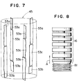
- the two resistance claws 53a and 53b provided in every four circumferential points are assumed to have the same length and the same configuration, respectively, and however, the resistance claws 53 provided in at least one of four circumferential points, e.g., in all of the four points, may be made of different combination of the resistance claws 53a, 53b and the like, as shown in Figure 7.
- the resistance imparted to the flow of rice grains can be adjusted or changed delicately as the more than two resistance claws are held in vertical positions.
- the cylindrical cover 44 serving as an outer peripheral wall of the bran removing chamber 43 has fitting portions 74 in portions thereof corresponding to the knob bolts 57, and an outer cover 76 of the knob bolt 57 is fitted in a bent portion 75 of each of the fitting portions 74.
- An outer surface 76a of the cover 76 is marked with a scale which shows the adjusted distance J of the resistance claw 53 proportional to the turning angle of the knob bolt 57 for adjustment.
- each of the bent portions 75 of the cover 44 is further extended so as to cover around the movable portion of the knob bolt 57 within the bran removing chamber 43.
- Each of the extended portions 77 is further fitted detachably on a fixed seat 78 of the stanchion 51.
- reference numeral 81 denotes a hollow bottomless feed roll having a feed screw on the outer peripheral surface thereof.
- the feed roll 81 is set on the uppermost roll element 14 while being fitted at a boss portion 81a thereof on the main shaft 3 and securely fixed to the main shaft 3 together with the abrasive roll assembly 16 by means of a bolt 82 screwed in a tapped hole in the upper end of the main shaft 3.
- reference numeral 83 denotes a feed cylinder which forms a supply chamber 84 of the rice grains to be whitened in cooperation with the feed roll 81, and a flange portion 83a at the lower end of the feed cylinder 83 is set on and fixed to the upper end of the stanchion 51 and the cylindrical cover 44 as a part of the frame of the rice whitening machine 1.
- reference numeral 86 denotes a hopper into which the rice grains to be whitened are thrown
- 87 denotes an upper rice grain guide member
- 88 denotes a feed amount regulating gate.
- the gate 88 is operated manually through a handle 89 or automatically by a motor 90 so as to adjust a position of a movable plate 91 with an opening 91a with respect to a bottom opening 86a of the hopper 86, so that the amount of rice grains to be fed from the hopper 86 into the supply chamber 84 is regulated.
- Reference numeral 92 denotes a lower guide member serving to feed the rice grains introduced through the gate 88 into the supply chamber 84 while dispersing the same.
- Reference numeral 95 denotes a resistance board provided at a discharge port 96 through which the rice grains having been whitened in the rice whitening chamber 40 are discharged.
- a pressing force applied to the rice grains in the rice whitening chamber 40 by the resistance board 95 is regulated by adjusting the position of a weight 99 screwed to one arm 98a of a lever 98 supported by a pivot shaft 97 by means of a handle (knob) 100.
- Numeral 101 denotes an expansion spring 101.
- Reference numeral 103 denotes a bran collecting fan which serves to release through an exhaust pipe 105 the bran collected in a bran collecting chamber 104 formed at the bottom of the bran removing chamber 43.
- a bottom cylindrical member 106 defining the inner peripheral wall of the bran collecting chamber 104 is fixed to the lower rotary bottom member 11, and the bottom cylindrical member 106 is provided with discharge blades 107 serving to promote the discharge of the bran from the bran collecting chamber 104 when the bottom cylindrical member 106 is rotated together with the lower rotary bottom member 11.
- the rice whitening conditions of the abrasive type vertical rice whitening machine 1 are set and adjusted in accordance with the characteristics or properties of the rice grains to be whitened.
- the radial positions of the resistance claws 53a and 53b are adjusted by handling the knob bolts 57 and the set bolts 59 while considering the diameter and rotational speed of the abrasive roll assembly 16, the abrasive characteristic of the abrasive roll element 14, the bran removing characteristic of the bran removing system including the exhaust fan 103 and so on.
- the distance J1 between the upper resistance claw 53a and the abrasive roll element 14 is adjusted and set mainly in accordance with relationship between sizes of the rice grains to be whitened in both directions of long and short axes thereof before rice whitening and desired sizes of the rice grains after rice whitening, while the distance J2 between the lower resistance claw 53b and the abrasive roll element 14, that is, a difference (J1 - J2) in radial position between the lower resistance claw 53b and the upper resistance claw 53a is adjusted and set mainly in accordance with the desired sizes (generally, shape) of the rice grains in both directions of long and short axes thereof obtained after rice whitening.
- the distance J2 between the lower resistance claw 53b and the abrasive roll element 14 is generally set to be rather large with the decrease of the hardness of the surface layer to be removed by the rice whitening machine 1.
- the above adjustment of the distances J1 and J2 may be even performed during the rice whitening operation while stopping the rotation of the abrasive roll assembly 16 (or while permitting the roll assembly 16 to rotate under certain circumstances).
- the pressing force resulting from the resistance board 95 that is, the pressure applied to the rice grains in the rice whitening chamber 40 by the resistance board 95 is regulated.
- this pressure regulation may be performed during the rice whitening as well.
- the cover 86b is opened and the rice grains to be whitened are thrown into the hopper 86 as the gate 88 is being closed and, at the same time, the motor 6 is started to rotate the abrasive roll assembly 16 and the feed roll 81 through the main shaft 3, with a result that the exhaust fan 103 is started so as to begin blowing of air for bran removing.
- the handle 89 or the motor 90 is operated to open the feed amount regulating gate 88 so that the rice grains to be whitened are started to be introduced into the supply chamber 84 from the hopper 86.
- the rice grains are supplied continuously into the supply chamber 84 as being dispersed uniformly in the circumferential direction by means of the upper and lower guide members 87 and 92.
- the rice grains received in the supply chamber 84 are fed continuously to an upper end 40c of the rice whitening chamber 40 by means of the feed roll 81.
- the rice grains supplied in the rice whitening chamber 40 come downwards gradually while repeating intermittent rolling and rotating or revolving (or moving around the main shaft in circular motion) between the stationary porous or perforated cylindrical body 42 and the rotating abrasive roll assembly 16 under the relatively low pressing force, during which the surface of the rice grains is made to come in contact with the abrasive cylinder 26 of the roll element 14 of the abrasive roll assembly 16 so as to be scraped off by the abrasive cylinder 26.
- the rotating or revolving speed thereof is reduced under the influence of braking action and a large difference comes out between the rotating (revolving) speed thereof and the rotational speed of the abrasive roll assembly 16, with a result that the surface of the rice grains is scraped off by being rubbed intensively with the emery particles of the abrasive cylinder 26 of the roll assembly 16.
- the resistance claws 53a have the function of braking the general or collective flow of the rice grains in the rice whitening chamber 40, the rolling speed and the rotating speed of the rice grains in the rice whitening chamber 40 are changed intermittently, with a result that the rice whitening proceeds gradually. Moreover, since the relation between the rolling speed and the rotating or revolving speed of the rice grains can be changed delicately by the adjustment of the resistance claws 53a, the shape of the rice grains to be discharged after whitening can be also changed by making use of this relation.
- the rice grains which have been partially whitened in the upper part 40a of the rice whitening chamber 40 and hence a little reduced in size, reach a lower part 40b of the rice whitening chamber 40, they receive the whitening action by the resistance claws 53b in a different way from the resistance claws 53a because, as seen from the above description, the distance J2 between the resistance claws 53b and the abrasive roll elements 14 is set to a suitable value which is different from the distance J1 between the resistance claws 53a and the abrasive roll elements 14. Accordingly, it is possible to perform the desired rice whitening not only in the upper part 40a but also in the lower part 40b of the rice whitening chamber 40.
- the rice grains having been whitened are collected in a collector portion 108 below a lower end 40d of the rice whitening chamber 40.
- the rice grains in the collector portion 108 are gathered in a stacker 112 through a chute 111 by opening the bottom resistance board 95 against the pressing force of the weight 99 while being stirred by the rotary stirring blades 12 attached to the lower rotary bottom member 11.
- the exhaust fan 103 As the exhaust fan 103 is operated, air is flow out or exhausted through the exhaust pipe 105. Therefore, there is generated a stream or flow of air passing through the inside passage 31 of the main shaft 3, the air holes 29 and 30, the jet-air outlets 36, the rice whitening chamber 40, the holes 41 of the porous or perforated cylindrical body 42 and the bran removing chamber 43 in the mentioned order. Owing to this stream of air, the powdered matter such as bran having been produced in the rice whitening chamber 40 during the rice whitening is discharged to the bran removing chamber 43 through the holes or perforations 41 of the porous cylindrical body 42. Further, the stream of air within the rice whitening chamber 40 serves to suppress rise of temperature of the rice grains in the rice whitening chamber 40.
- the stream of air coming from the jet-air outlets 36 serves to remove the bran and the like matter also from the gap 72 between the resistance claws 53a and 53b.
- the bran having been introduced in the bran removing chamber 43 is collected in the bran collecting chamber 104 and discharged by the discharge blades 107.
- the hopper 86 is also formed with an airflow passage (not shown) so that air having passed through this airflow passage into the hopper 86 also serves to assist the discharge of the bran from the rice whitening chamber 40.
- the bran which comes in to the depth of the jet-air outlets 36 can be returned into the rice whitening chamber 40 due to the centrifugal force resulting from the rotation of the arms 33 as well as the air stream or flow.
- the grain to be milled may be other grain such as wheat grain in place of rice grain.
- the grain milling conditions of the grain milling machine are changed in accordance with the grain size originating diffences in kind of grains as well as with the thickness, hardness and the like of the surface layer to be removed.
- the position adjusting mechanism of the resistance claw may be for example a piston-cylinder assembly and other like means in place of the knob bolt employed in the illustrated embodiment. Further, these may be the ones which are driven electrically or by fluid pressure.
Landscapes
- Adjustment And Processing Of Grains (AREA)
- Crushing And Grinding (AREA)
Description
- The present invention refers to an abrasive type vertical grain milling machine comprising:
- an abrasive type grain milling roll assembly mounted on a main shaft extending straight in a vertical direction; and a perforated cylindrical body extending vertically around said roll assembly leaving a space therefrom so as to define a cylindrical grain milling chamber around said roll assembly in cooperation with an outer peripheral surface of said roll assembly and having a large number of holes through which bran produced in said grain milling chamber is allowed to be released, the grain milling chamber having a vertical one end where grains to be milled are introduced and another end from where grains having been milled are discharged, said cylindrical body comprises a plurality of vertically arranged resistance members projected radially into the grain milling chamber so as to impart resistances to motions of the grains in a circumferential direction of said roll assembly, an amount of projection of each of said resistance members being made to be adjustable, and projection amount adjusting means for adjusting independently the respective amounts of projection in the radial direction of said plural resistance members located in different vertical positions, said cylindrical body comprises a plurality of stanchions circumferentially spaced apart from each other and extending substantially in the vertical direction, and perforated arcuate plate members, disposed between the circumferentially adjacent stanchions and each forming a part of a cylinder of said cylindrical body, and said plural stanchions so as to be located in different vertical positions on a side of the associated stanchion facing to the grain milling chamber through said projection amount adjusting means while being movable in the radial direction of said roll assembly with respect to the associated stanchion.
-
- Such an abrasive type vertical grain milling machine is known from CH-A-280080. In a grain milling machine, the grains to be milled, such as rice grains, are introduced into the milling or whitening chamber from an upper end thereof. The grains are forcibly rotated in a circumferential direction by the grain milling roll assembly. The rice grains rub against each other and other surfaces thereof are scraped so that they are milled, or whitened. Rubbing between the rice grains becomes more intense as the amount of the projection of the resistance members is increased to impart a higher resistance to the movement of the rice grains in a circumferential direction, which results in the milling or whitening action being performed more powerfully. However, since the size of the rice grains become smaller with the progress of the milling, or whitening of the rice grain, and the steady state of the machine when the rice grains are supplied at a constant flow rate, for example, the resistance imparted to the movement of the flow of the rice grains becomes smaller in the downstream-side region of the whitening chamber as compared with the upstream-side region of the same. Accordingly, there is a possibility that in the downstream-side region, since the intensity of the rubbing between the rice grains, which depend on the amount of projection of the resistance members, becomes lower as compared with the upstream-side region, it becomes hardly possible to achieve a sufficient whitening action. In an abrasive type grain milling machine, this tendency is remarkable. In the case of use of a resistance member adjusting means, it may become difficult to adjust the mechanism during the whitening action.
- The grain milling machine, according to CH-A-280080, is, therefore, provided with several independently adjustable resistance members located in different vertical positions. The resistance members are of equal size and have to be adjusted individually.
- Adjusting these resistance members, however, is rather time-consuming, particularly if different grains have to be milled and the machine has to be adjusted accordingly.
- There has, therefore, been a need for an abrasive type vertical grain milling machine. according to the afore-mentioned type, that allows easier adjustment of the resistance members for milling different kinds of grains.
- The object has been achieved, according to an abrasive type vertical grain milling machine of the afore-mentioned type, wherein resistance members in different positions are different in length.
- This allows as easy adjustment of the different resistance members according to the milling profile. For example, shorter resistance members on the upstream side allow a fine adjustment of the distance between the roll assembly and the resistance members compared to the downstream side. Also, the number of resistance members on the downstream side is, then, fewer than on the upstream side and, therefore, requires only a minimum number of resistance members to be adjusted.
- According to the present invention, it is preferred that each of the plural resistance members supported by said each stanchion extends in the vertical direction and a distance between adjacent end portions of the vertically adjacent resistance members is smaller than a size of the grains to be milled.
- In this case, there is no possibility that the small gap between the adjacent end portions of the resistance members is clogged with the grains and the like.
- According to the present invention, it is preferred that each of the stanchions has a substantially U-letter form cross-section and a concave portion of the "U" faces toward the roll assembly so that the plural resistance members supported by said each stanchion are located within the concave portion at radially outward parts thereof with respect to the roll assembly.
- In this case, the positions of the plural resistance members can be easily adjusted independently with a relatively simple construction.
- According to the present invention, it is preferred that the projection amount adjusting means is adapted to be able to make each of the resistance members project radially inwardly until the resistance member is brought into contact with the outer peripheral surface of the roll assembly.
- In this case, even the milling of for example the grains the average size of which is different can be performed by adjusting the radial position(s) of the resistance member(s).
- According to the present invention, it is preferred that the roll assembly comprises a plurality of roll elements fitted on the main shaft while being spaced from each other in the vertical direction in which the main shaft extends, and adjacent end portions of the vertically adjacent resistance members defines a small gap therebetween at a level of the space between the roll elements.
- In this case, there is little possibility that the grains are pressed into the small gap owing to the pressing force applied to the grains by the roll elements during the abrasive operation.
- Further, it is also possible that the roll assembly comprises a plurality of roll elements fitted on the main shaft while being spaced from each other in the vertical direction in which the main shaft extends, and adjacent end portions of the vertically adjacent resistance members defines a small gap therebetween at a level where it faces to the outer peripheral surface of one of the roll elements.
- In this case, it is necessary or desired to make the gap between the both upper and lower resistance members as small as possible.
- Moreover, the amount of projection of each resistance member at the upstream and downstream ends thereof may be different. For example, a single resistance member may be so disposed as to project the more as going toward the downstream side.
- In this case, the distance between the surface of the roll assembly and the resistance member is suitably changed in accordance with the details of the desired grain milling action.
- The foregoing and other objects, features as well as advantages of the invention will be made clearer hereafter from detailed description of preferred embodiments with reference to drawings.
-
- Figure 1 is a vertical sectional view of an abrasive type vertical grain milling machine according to a preferred embodiment of the present invention (or a sectional view of Figure 3 taken along the line I-I);
- Figure 2 is an enlarged sectional view of a part of the grain milling machine of Figure 1;
- Figure 3 is a cross-sectional view of the grain milling machine of Figure 1 taken along the line III-III;
- Figure 4 is an explanatory view showing, in exaggeration, relation (distance relation) between resistance claws and an abrasive roll assembly of the grain milling machine of Figure 1;
- Figure 5 is an explanatory view of a modification of the arrangement of the resistance claws shown in Figure 4;
- Figure 6 is an explanatory view of another modification of the arrangement of the resistance claws shown in Figure 4;
- Figure 7 is an explanatory view of still another modification of the arrangement of the resistance claws shown in Figure 4; and
- Figure 8 is an explanatory view showing relation between an abrasive roll assembly and a feed roll in a modification of the abrasive type vertical grain milling machine of Figure 1.
-
- Next, taking a case of milling or whitening rice grain as an example of cereal grain, an abrasive type vertical rice whitening machine, which is a preferred embodiment of an abrasive type vertical grain milling machine according to the present invention, will be described with reference to Figures 1 to 4.
- In Figure 1 which is a general vertical sectional view of an abrasive type vertical rice whitening machine 1,
reference numeral 2 denotes a base. In the central portion of thebase 2, amain shaft 3 constituted by a hollow shaft extending in the vertical direction is rotatably supported by means of upper andlower bearings 4 and 5. Amotor 6 is equipped sidewards of thebase 2 so that rotation of anoutput shaft 7 of themotor 6 is transmitted through a pulley 8, a wedge belt orV belt 9 and apulley 10 to themain shaft 3, thereby making themain shaft 3 rotate at a suitable rotational speed (generally at a rotational speed where a peripheral speed of an abrasivetype roll assembly 16 to be described later becomes about 600 m/min at an outer peripheral surface thereof). - A lower rotary bottom member 11 having a cap-like cross-section is fixed to the
main shaft 3 such as to be positioned above the upper bearing 4, and an upperrotary bottom member 13 formed with stirringblades 12 serving to discharge the whitened or milled white rice is fixed to the lower rotary bottom member 11. - The upper
rotary bottom member 13 has a radiallyoutward flange portion 17 on which is supported a bottom portion of the abrasivetype roll assembly 16 constituted by a stack of a large number of abrasivetype roll elements 14 withroll element spacers 15 interposed therebetween. - Each
roll element 14 comprises a rigid abrasivecylinder support member 24 including aboss portion 21 fitted on themain shaft 3, a plurality ofarm portions 22 formed integrally with theboss portion 21 and extending radially outwardly from theboss portion 21 and acylindrical portion 23 formed integrally with the extended ends of thearm portions 22, and anabrasive cylinder 26 securely fixed to thesupport member 24 and formed by an aggragate of emery particles (Carborundom (trademark)). - Incidentally, among the
abrasive cylinders 26, the uppermost abrasive cylinder, that is, anabrasive cylinder 26a located on the most upstream side of the flowing direction of rice grains to be whitened, is formed in the shape of a circular truncated cone in order to guide the rice grains or the flow of rice grains. - Further, the hollow
main shaft 3 is formed with a large number ofair holes 29 in the portion thereof where the abrasive type roll assembly is fitted on, and theboss portion 21 of the abrasivecylinder support member 24 of each of theroll elements 14 is also formed therein withair holes 30. Accordingly, in case that the abrasivecylinder support member 24 of theroll element 14 is fitted on the hollowmain shaft 3, at least a part of theair holes 30 formed in eachboss portion 21 are communicated with at least a part of theair holes 29 formed in themain shaft 3, thereby enabling air to flow from aninterior space 31 of the hollowmain shaft 3 to the inside of theabrasive cylinder 26 through theair holes - On the other hand, each of the
roll element spacers 15 comprises, as shown in Figure 3, aboss portion 32 having a larger outer diameter than theboss portion 21 and a plurality ofarm portions 33 formed integrally with theboss portion 32 and extending substantially radially outwardly from theboss portion 32. Eacharm portion 33 comprises a base-side arm portion 34 extending straight in the radial direction and a tapered tip end-side arm portion 35 extending radially outwardly from the end of the base-side arm portion 34 as turning aside in the direction opposite to the direction of rotation of thespacer 15. - Accordingly, the air having flown out from the
interior space 31 of the hollowmain shaft 3 to the inside of theabrasive cylinder 26 through theair holes spaces 36 defined between theadjacent arm portions roll element spacer 15 and through between theadjacent roll elements spaces 36 serve as the bran removing jet-air outlets of the abrasivetype roll assembly 16. - Around the abrasive
type roll assembly 16 is disposed a porous or perforatedcylindrical body 42 which cooperates with the outer peripheral surface of theroll assembly 16 to form a cylindrical grain milling chamber or arice whitening chamber 40 around theroll assembly 16. The porouscylindrical body 42 extends vertically leaving a space from theroll assembly 16 and has a large number of holes 41 through which bran produced in therice whitening chamber 40 is allowed to be released. Around the porouscylindrical body 42 is disposed acylindrical cover 44 which cooperates with the porouscylindrical body 42 to define abran removing chamber 43 serving to collect and discharge the bran. - The porous
cylindrical body 42 and thecylindrical cover 44 are set on and fixed to a double-cylindrical support member 2a fixed to thebase 2. The double-cylindrical support member 2a comprises an outercylindrical support portion 2b fixed to thebase 2 at a bottom flange thereof,ribs 2c projecting inwardly from the outercylindrical support portion 2b at four circumferential points and an innercylindrical support portion 2d formed integral with the outercylindrical support portion 2b through theribs 2c. - As shown in Figure 3, the porous
cylindrical body 42 comprises four resistance imparting-adjusting mechanisms 45 disposed in such circumferential positions that the cylinder defined by thecylindrical body 42 is divided into four equal parts, and metallic porous or perforatedarcuate plate members 46 serving to define the cylindrical surface portions between the adjacent resistance imparting-adjusting mechanisms bran removing chamber 43 is divided into four sections or four chambers by the four resistance imparting-adjustingmechanisms 45. The number of the resistance imparting-adjustingmechanisms 45 may be either not greater than 3 or not smaller than 5. The plural resistance imparting-adjustingmechanisms 45 are arranged equidistantly in the circumferential direction of thecylindrical body 42 as shown in Figure 3, for example. Further, as seen from Figures 1 and 2, the flow resistance imparting-adjustingmechanisms 45 and the porousarcuate plate members 46 are respectively formed to extend over the entire vertical length of therice whitening chamber 40. A distance H between the inner peripheral surface of theporous plate member 46 and the outer peripheral surface of theabrasive roll element 14 is in the range of about 10 ∼ 15 mm, for example. The distance H is decided in accordance with the kind of grain to be milled, size of emery particles of theabrasive roll element 14, rotational speed of theabrasive roll element 14 and the like. - Each flow resistance imparting-adjusting mechanism 45 comprises a stanchion or support post 51 of a substantially U-letter form cross-section extending in the vertical direction and set on and fixed to upper ends of the ribs 21c through a bottom plate 50, prismatic resistance claws 53a and 53b made of for example rubber and fitted disengageably in a concave portion 52, which extends in the vertical direction of "U" of each stanchion 51 and opens radially inwardly, so as to serve as upper and lower resistance members (in case of generally calling the upper and lower resistance claws, they are designated by the reference numeral 53), knob bolts 57 as adjusting member screwed in upper and lower tapped holes 54 and 55 of the respective resistance claws 53 at external thread portions 56 thereof so as to adjust the radial positions of the resistance claws 53 with respect to the stanchion 51 (in other words, distances J1 and J2 between the upper and lower resistance claws 53a, 53b and the abrasive roll element 14 (in case of generally calling, these distances are designated by the reference character J)), and set bolts 59 screwed in tapped holes of the stanchion 51 for serving, after the adjustment of the positions of the resistance claws 53, to fix the resistance claws 53 with respect to the stanchion 51 by making the tip ends thereof come in contact with an outside end faces 58 of the resistance claws 53 (hereinafter, suffixes a and b will be added, as occasion demands, even in case of describing about the member or portion which is provided equally to the upper and lower resistance members such as the knob bolt 57 and the set bolt 59, that is, the suffix a will be added for the members or portions associated with the upper resistance claw while the suffix b for the members or portions associated with the lower resistance claw). The
resistance claws 53 may be made of a plastic or metallic material having suitable strength and hardness, in place of rubber. - In more detail, prismatic reinforcing
pieces stanchion 51 at the inner peripheral ends of thestanchion 51 and on both sides of theconcave portion 52, thereby forming astanchion assembly 63 as a whole. Incidentally, each reinforcingpiece 62 projects a little radially inward beyond the porousarcuate plate member 46 bent in the form of a circular arc by about 2 mm, for example. On the other hand, circumferentialend edge portions arcuate plate member 46 are pressed on and fixed to side walls of the associatedstanchion assemblies 63 by means of stiffeningplates 64. -
Reference numeral 66 denotes hollow stud bolts. A small diameter external thread portion 66a of thebolt 66 is screwed in the tapped hole of thestanchion 51, while anut 68 serving to fix acover 67 is screwed to a large diameterexternal thread portion 66b of thebolt 66. On the other hand, theexternal thread portion 56 of theknob bolt 57 is loosely fitted in asmall diameter portion 69a of ahole 69 of thehollow bolt 66, while alarge diameter portion 57A of theknob bolt 57 is rotatably inserted in alarge diameter portion 69b of thehole 69. Incidentally, in a state that anend face 57B of thelarge diameter portion 57A of theknob bolt 57 is in contact with a steppedportion 69c of the wall of thehole 69, astopper ring 70 is fitted in anannular groove 57C of theknob bolt 57 and the end portion of thestud bolt 66 is caulked, thereby prohibiting theknob bolt 57 from displacing in the axial direction thereof with respect to thebolt 66 and, hence, to thestanchion 51. - In case of adjusting the distance J between the
resistance claw 53 and theroll element 14, theset bolt 59 is first unfastened or loosened and, then, theknob bolts 57 screwed respectively in the tappedholes 54 of thestanchion 51 are turned so as to make the upper and lower portions of theresistance claw 53 come close to and away from theroll element 14 by a specified length. Subsequently, theset bolt 59 is fastened again finally. - Usually, in order to make the
resistance claw 53 extend substantially exactly in the vertical direction, angles through which theknob bolts 57 are turned with respect to the tappedholes 54 for adjustment are made equal to each other. However, if desired, the angles through which theknob bolts holes 54, 55 for adjustment may be differed from each other so as to slightly incline theresistance claw 53 in such a manner that the distance J between theresistance claw 53 and theabrasive roll assembly 16 becomes smaller or larger as going downwards, for example. In this case, a vertical discrepancy (or the angle of inclination) is small as compared with the length of theresistance claw 53. - The above operation of adjusting the position of the resistance claw is performed independently for each of the upper and
lower resistance claws knob bolts bolts rice whitening chamber 40 with the progress of the whitening of the surface of rice grains because the bran can be easily removed from therice whitening chamber 40 sufficiently, the distance J1 between theupper resistance claw 53a and theabrasive roll assembly 16 is made larger than the distance J2 between thelower resistance claw 53b and the abrasive roll assembly 16 (see Figure 4). On the other hand, in case that it is difficult to remove the bran sufficiently and hence the bran is apt to be collected in a lower part of therice whitening chamber 40, the distance J1 between theupper resistance claw 53a and theabrasive roll assembly 16 is made smaller than the distance J2 between thelower resistance claw 53b and theabrasive roll assembly 16. Incidentally, in selecting and setting the distances J1, J2 between the upper andlower resistance claws abrasive roll assembly 16, other various reasons or conditions as desired are taken into consideration. - Further, in the case shown in Figures 1 to 4, the
upper resistance claw 53 is shorter in vertical length than thelower resistance claw 53b, and however, the length of theupper resistance claw 53a may be made longer than the length of thelower resistance claw 53b as shown in Figure 5. Moreover, as shown byimaginary line 80 in Figure 4, theresistance member 53 may be formed therein with grooves at positions thereof facing to the jet-air outlets 36 in order to prevent the jet-air outlets 36 and the vicinity thereof from being clogged with the rice grains. - In addition, in the case illustrated in Figures 1 and 2, a
small gap 72 between the lower end of theupper resistance claw 53a and the upper end of thelower resistance claw 53b is situated just at a level facing to the jet-air outlet 36 between theroll elements imaginary line 72a in Figure 4, the lengths of the upper andlower resistance claws gap 72a at a level where it faces to the outer peripheral surface of one of theplural roll elements 14. Incidentally, although theresistance claw 53 is shown as being extended over the entire length of therice whitening chamber 40, it may be so provided as to extend over a part of the entire length of the same, that is, it may be so provided as to be present in a region not higher than a level ofimaginary line 79 as shown in Figure 4, for example. - Further, the size of the
gap 72 is selected to be in a range which can eliminate a possibility that the rice grains are caught or taken in the gap to hinder the flow of the rice grains to be whitened. Moreover, as shown byimaginary line 72b in Figure 4, at least one of the lower end of theupper resistance claw 53a and the upper end of thelower resistance claw 53b may be tapered or rounded. - In addition, the number of the
resistance claws 53 which are supported substantially in series by asingle stanchion assembly 63 and have their positions adjusted by theknob bolts 57 and theset bolt 59 individually or independently may be three as shown in Figure 3 or more, in place of two. - Further, in the above description, the two
resistance claws resistance claws 53 provided in at least one of four circumferential points, e.g., in all of the four points, may be made of different combination of theresistance claws - In the case shown in Figures 6 and 7, the resistance imparted to the flow of rice grains can be adjusted or changed delicately as the more than two resistance claws are held in vertical positions.
- Referring back to Figure 3, as shown therein in detail, the
cylindrical cover 44 serving as an outer peripheral wall of thebran removing chamber 43 hasfitting portions 74 in portions thereof corresponding to theknob bolts 57, and anouter cover 76 of theknob bolt 57 is fitted in abent portion 75 of each of thefitting portions 74. Anouter surface 76a of thecover 76 is marked with a scale which shows the adjusted distance J of theresistance claw 53 proportional to the turning angle of theknob bolt 57 for adjustment. Incidentally, each of thebent portions 75 of thecover 44 is further extended so as to cover around the movable portion of theknob bolt 57 within thebran removing chamber 43. Each of theextended portions 77 is further fitted detachably on a fixedseat 78 of thestanchion 51. - Referring back to Figures 1 and 2,
reference numeral 81 denotes a hollow bottomless feed roll having a feed screw on the outer peripheral surface thereof. Thefeed roll 81 is set on theuppermost roll element 14 while being fitted at a boss portion 81a thereof on themain shaft 3 and securely fixed to themain shaft 3 together with theabrasive roll assembly 16 by means of abolt 82 screwed in a tapped hole in the upper end of themain shaft 3. Further, reference numeral 83 denotes a feed cylinder which forms asupply chamber 84 of the rice grains to be whitened in cooperation with thefeed roll 81, and a flange portion 83a at the lower end of the feed cylinder 83 is set on and fixed to the upper end of thestanchion 51 and thecylindrical cover 44 as a part of the frame of the rice whitening machine 1. - In addition,
reference numeral 86 denotes a hopper into which the rice grains to be whitened are thrown, 87 denotes an upper rice grain guide member, and 88 denotes a feed amount regulating gate. Thegate 88 is operated manually through ahandle 89 or automatically by amotor 90 so as to adjust a position of amovable plate 91 with an opening 91a with respect to abottom opening 86a of thehopper 86, so that the amount of rice grains to be fed from thehopper 86 into thesupply chamber 84 is regulated. Reference numeral 92 denotes a lower guide member serving to feed the rice grains introduced through thegate 88 into thesupply chamber 84 while dispersing the same. -
Reference numeral 95 denotes a resistance board provided at adischarge port 96 through which the rice grains having been whitened in therice whitening chamber 40 are discharged. A pressing force applied to the rice grains in therice whitening chamber 40 by theresistance board 95 is regulated by adjusting the position of aweight 99 screwed to onearm 98a of a lever 98 supported by apivot shaft 97 by means of a handle (knob) 100.Numeral 101 denotes anexpansion spring 101. -
Reference numeral 103 denotes a bran collecting fan which serves to release through anexhaust pipe 105 the bran collected in abran collecting chamber 104 formed at the bottom of thebran removing chamber 43. Incidentally, a bottom cylindrical member 106 defining the inner peripheral wall of thebran collecting chamber 104 is fixed to the lower rotary bottom member 11, and the bottom cylindrical member 106 is provided withdischarge blades 107 serving to promote the discharge of the bran from thebran collecting chamber 104 when the bottom cylindrical member 106 is rotated together with the lower rotary bottom member 11. - Next, description will be given of handling and operation of the rice whitening machine 1 thus constructed which is a preferred embodiment of the abrasive type vertical grain milling machine according to the present invention, with reference to Figures 1 to 4.
- First, the rice whitening conditions of the abrasive type vertical rice whitening machine 1 are set and adjusted in accordance with the characteristics or properties of the rice grains to be whitened.
- More specifically, in accordance with various properties such as the shape of grain determined by the sizes of the rice grains to be whitened in both directions of long (minor) and short (minor) axes thereof before rice whitening, the average sizes of the rice grains in both directions of long and short axes thereof obtained after rice whitening, and the thickness and hardness of the surface layer of rice grain to be removed by the rice whitening machine 1, the radial positions of the
resistance claws knob bolts 57 and the setbolts 59 while considering the diameter and rotational speed of theabrasive roll assembly 16, the abrasive characteristic of theabrasive roll element 14, the bran removing characteristic of the bran removing system including theexhaust fan 103 and so on. - The distance J1 between the
upper resistance claw 53a and theabrasive roll element 14 is adjusted and set mainly in accordance with relationship between sizes of the rice grains to be whitened in both directions of long and short axes thereof before rice whitening and desired sizes of the rice grains after rice whitening, while the distance J2 between thelower resistance claw 53b and theabrasive roll element 14, that is, a difference (J1 - J2) in radial position between thelower resistance claw 53b and theupper resistance claw 53a is adjusted and set mainly in accordance with the desired sizes (generally, shape) of the rice grains in both directions of long and short axes thereof obtained after rice whitening. - Incidentally, the distance J2 between the
lower resistance claw 53b and theabrasive roll element 14 is generally set to be rather large with the decrease of the hardness of the surface layer to be removed by the rice whitening machine 1. The above adjustment of the distances J1 and J2 may be even performed during the rice whitening operation while stopping the rotation of the abrasive roll assembly 16 (or while permitting theroll assembly 16 to rotate under certain circumstances). - On the other hand, by adjusting the position of the
weight 99 on thelever 98a by turning theknob 100, the pressing force resulting from theresistance board 95, that is, the pressure applied to the rice grains in therice whitening chamber 40 by theresistance board 95 is regulated. Incidentally, this pressure regulation may be performed during the rice whitening as well. - After the initialization described above, the
cover 86b is opened and the rice grains to be whitened are thrown into thehopper 86 as thegate 88 is being closed and, at the same time, themotor 6 is started to rotate theabrasive roll assembly 16 and thefeed roll 81 through themain shaft 3, with a result that theexhaust fan 103 is started so as to begin blowing of air for bran removing. - Subsequently, the
handle 89 or themotor 90 is operated to open the feedamount regulating gate 88 so that the rice grains to be whitened are started to be introduced into thesupply chamber 84 from thehopper 86. In this case, the rice grains are supplied continuously into thesupply chamber 84 as being dispersed uniformly in the circumferential direction by means of the upper and lower guide members 87 and 92. The rice grains received in thesupply chamber 84 are fed continuously to anupper end 40c of therice whitening chamber 40 by means of thefeed roll 81. - In the steady state of the rice whitening operation of the rice whitening machine 1, the rice grains supplied in the
rice whitening chamber 40 come downwards gradually while repeating intermittent rolling and rotating or revolving (or moving around the main shaft in circular motion) between the stationary porous or perforatedcylindrical body 42 and the rotatingabrasive roll assembly 16 under the relatively low pressing force, during which the surface of the rice grains is made to come in contact with theabrasive cylinder 26 of theroll element 14 of theabrasive roll assembly 16 so as to be scraped off by theabrasive cylinder 26. In more detail, since the rice grains are caught between theresistance claws 53a and theabrasive roll assembly 16 when they reach theresistance claws 53a, the rotating or revolving speed thereof is reduced under the influence of braking action and a large difference comes out between the rotating (revolving) speed thereof and the rotational speed of theabrasive roll assembly 16, with a result that the surface of the rice grains is scraped off by being rubbed intensively with the emery particles of theabrasive cylinder 26 of theroll assembly 16. Further, since theresistance claws 53a have the function of braking the general or collective flow of the rice grains in therice whitening chamber 40, the rolling speed and the rotating speed of the rice grains in therice whitening chamber 40 are changed intermittently, with a result that the rice whitening proceeds gradually. Moreover, since the relation between the rolling speed and the rotating or revolving speed of the rice grains can be changed delicately by the adjustment of theresistance claws 53a, the shape of the rice grains to be discharged after whitening can be also changed by making use of this relation. - When the rice grains, which have been partially whitened in the
upper part 40a of therice whitening chamber 40 and hence a little reduced in size, reach alower part 40b of therice whitening chamber 40, they receive the whitening action by theresistance claws 53b in a different way from theresistance claws 53a because, as seen from the above description, the distance J2 between theresistance claws 53b and theabrasive roll elements 14 is set to a suitable value which is different from the distance J1 between theresistance claws 53a and theabrasive roll elements 14. Accordingly, it is possible to perform the desired rice whitening not only in theupper part 40a but also in thelower part 40b of therice whitening chamber 40. - In addition, since a specified exit pressure is applied to the
rice whitening chamber 40 by theresistance board 95 which is applied with the force of theweight 99, in case of whitening the rice grains in the aforementioned manner, the rice grains are abraded and whitened in the state that they are filled in therice whitening chamber 40 at a suitable density so far as the rice grains are allowed to flow continuously. - The rice grains having been whitened are collected in a
collector portion 108 below alower end 40d of therice whitening chamber 40. The rice grains in thecollector portion 108 are gathered in astacker 112 through a chute 111 by opening thebottom resistance board 95 against the pressing force of theweight 99 while being stirred by therotary stirring blades 12 attached to the lower rotary bottom member 11. - Meanwhile, as the
exhaust fan 103 is operated, air is flow out or exhausted through theexhaust pipe 105. Therefore, there is generated a stream or flow of air passing through theinside passage 31 of themain shaft 3, the air holes 29 and 30, the jet-air outlets 36, therice whitening chamber 40, the holes 41 of the porous or perforatedcylindrical body 42 and thebran removing chamber 43 in the mentioned order. Owing to this stream of air, the powdered matter such as bran having been produced in therice whitening chamber 40 during the rice whitening is discharged to thebran removing chamber 43 through the holes or perforations 41 of the porouscylindrical body 42. Further, the stream of air within therice whitening chamber 40 serves to suppress rise of temperature of the rice grains in therice whitening chamber 40. In addition, the stream of air coming from the jet-air outlets 36 serves to remove the bran and the like matter also from thegap 72 between theresistance claws bran removing chamber 43 is collected in thebran collecting chamber 104 and discharged by thedischarge blades 107. Further, thehopper 86 is also formed with an airflow passage (not shown) so that air having passed through this airflow passage into thehopper 86 also serves to assist the discharge of the bran from therice whitening chamber 40. Moreover, the bran which comes in to the depth of the jet-air outlets 36 can be returned into therice whitening chamber 40 due to the centrifugal force resulting from the rotation of thearms 33 as well as the air stream or flow. - The above description has been made as to the case that the rice grains are whitened while being made to flow from top to bottom, and however, an abrasive type vertical rice whitening machine of a lift type is also available in which the
feed roll 81 is disposed under theabrasive roll assembly 16 so that the rice grains are whitened while being made to flow from bottom to top in the upward direction of an arrow mark A as shown in Figure 8. - The grain to be milled may be other grain such as wheat grain in place of rice grain. In this case, the grain milling conditions of the grain milling machine are changed in accordance with the grain size originating diffences in kind of grains as well as with the thickness, hardness and the like of the surface layer to be removed.
- Incidentally, the position adjusting mechanism of the resistance claw may be for example a piston-cylinder assembly and other like means in place of the knob bolt employed in the illustrated embodiment. Further, these may be the ones which are driven electrically or by fluid pressure.
Claims (8)
- An abrasive type vertical grain milling machine comprising:an abrasive type grain milling roll assembly (16) mounted on a main shaft (3) extending straight in a vertical direction; anda perforated cylindrical body (42) extending vertically around said roll assembly leaving a space therefrom so as to define a cylindrical grain milling chamber (40) around said roll assembly in cooperation with an outer peripheral surface of said roll assembly and having a large number of holes through which bran produced in said grain milling chamber is allowed to be released, the grain milling chamber having a vertical one end where grains to be milled are introduced and another end from where grains having been milled are discharged,said cylindrical body comprises a plurality of vertically arranged resistance members (53) projected radially into the grain milling chamber so as to impart resistances to motions of the grains in a circumferential direction of said roll assembly an amount of projection of each of said resistance members being made to be adjustable, andprojection amount adjusting means (45) for adjusting independently the respective amounts of projection in the radial direction of said plural resistance members located in different vertical positions, said cylindrical body comprises a plurality of stanchions (51) circumferentially spaced apart from each other and extending substantially in the vertical direction, and perforated arcuate plate members (46), disposed between the circumferentially adjacent stanchions and each forming a part of a cylinder of said cylindrical body, and said plural stanchions so as to be located in different vertical positions on a side of the associated stanchion facing to the grain milling chamber through said projection amount adjusting means while being movable in the radial direction of said roll assembly with respect to the associated stanchion wherein resistance members in different verticle positions are different in length.
- An abrasive type verticle grain milling machine according to Claim 1, wherein a vertical length of a resistance member located on an upstream side in a direction of flow of the grains to be milled is shorter than that of a resistance member on a downstream side.
- An abrasive type vertical grain milling machine according to Claim 1 or 2, wherein each of the plural resistance members supported by said each stanchion extends in the vertical direction and a distance between adjacent end portions of the vertically adjacent resistance members is smaller than a size of the grains to be milled.
- An abrasive type vertical grain milling machine according to Claim 3, wherein each of the stanchions (51) has a substantially U-letter form cross-section and a concave portion (52) of the "U" faces toward said roll assembly so that said plural resistance members supported by said each stanchion are located within said concave portion at radially outward parts thereof with respect to said roll assembly (16).
- An abrasive type vertical grain milling machine according to Claim 1, further comprising plural bran removing chambers, each being formed between circumferentially adjacent stanchions.
- An abrasive type vertical grain milling machine according to Claim 1, wherein said projection amount adjusting means is adapted to be able to make each of said resistance members project radially inwardly until said resistance member is brought into contact with the outer peripheral surface of said roll assembly.
- An abrasive type vertical grain milling machine according to Claim 1, wherein said roll assembly comprises a plurality of roll elements (14) fitted on the main shaft (3) while being spaced from each other in the vertical direction in which the main shaft extends and adjacent end portions of the vertically adjacent resistance members defines a small gap therebetween at a level of the space between the roll elements.
- An abrasive type vertical grain milling machine according to Claim 1, wherein said roll assembly comprises a plurality of roll elements fitted on the main shaft wile being spaced from each other in the vertical direction in which the main shaft extends. and adjacent end portions of the vertically adjacent resistance members defines a small gap therebetween at a level where it faces to the outer peripheral surface of one of the roll elements.
Applications Claiming Priority (3)
| Application Number | Priority Date | Filing Date | Title |
|---|---|---|---|
| JP215072/93 | 1993-08-06 | ||
| JP21507293 | 1993-08-06 | ||
| JP21507293A JP3266167B2 (en) | 1993-08-06 | 1993-08-06 | Resistor adjustment device for vertical grinding type grain mill |
Publications (3)
| Publication Number | Publication Date |
|---|---|
| EP0637464A2 EP0637464A2 (en) | 1995-02-08 |
| EP0637464A3 EP0637464A3 (en) | 1995-03-22 |
| EP0637464B1 true EP0637464B1 (en) | 1999-12-22 |
Family
ID=16666295
Family Applications (1)
| Application Number | Title | Priority Date | Filing Date |
|---|---|---|---|
| EP94110137A Expired - Lifetime EP0637464B1 (en) | 1993-08-06 | 1994-06-29 | Resistance member adjusting mechanism of abrasive type grain whitening machines |
Country Status (11)
| Country | Link |
|---|---|
| US (1) | US5413034A (en) |
| EP (1) | EP0637464B1 (en) |
| JP (1) | JP3266167B2 (en) |
| KR (1) | KR0147206B1 (en) |
| AU (1) | AU660584B2 (en) |
| CA (1) | CA2125819C (en) |
| DE (1) | DE69422235T2 (en) |
| ES (1) | ES2141784T3 (en) |
| MY (1) | MY111003A (en) |
| PH (1) | PH31015A (en) |
| TW (1) | TW235253B (en) |
Families Citing this family (19)
| Publication number | Priority date | Publication date | Assignee | Title |
|---|---|---|---|---|
| JPH07227550A (en) * | 1994-02-17 | 1995-08-29 | Satake Eng Co Ltd | Grinding vertical grain mill |
| PH31195A (en) * | 1995-05-08 | 1998-04-24 | Satake Eng Co Ltd | Abrasive type vertical grain milling machine. |
| JPH09122510A (en) * | 1995-11-02 | 1997-05-13 | Satake Eng Co Ltd | Detachment device |
| US6409105B1 (en) | 1999-08-19 | 2002-06-25 | The Quaker Oats Company | Corn milling and separating device and method |
| US6234072B1 (en) * | 2000-03-06 | 2001-05-22 | John C. Kooima | Grain husk cracking plate |
| US6327970B1 (en) | 2000-03-06 | 2001-12-11 | John C. Kooima | Grain husk cracking plate |
| DE10251490A1 (en) * | 2002-11-04 | 2004-05-13 | Bühler AG | Procedure for husking and degerminating of especially corn entails degerminating grains directly or after surface dampening, and carrying out of procedure in treatment zone between beater bars of drum which has protrusions |
| DE10341223A1 (en) * | 2003-09-04 | 2005-03-24 | Bühler AG | Grinding or polishing machine |
| JP4610254B2 (en) * | 2004-07-29 | 2011-01-12 | 株式会社山本製作所 | Ken rice machine |
| CN100430142C (en) * | 2006-12-15 | 2008-11-05 | 肖崇业 | Ordered rice-husking process and machine |
| US20080226784A1 (en) * | 2007-03-15 | 2008-09-18 | Satake Usa, Inc. | Corn mill having increased through production |
| BR112013003447B1 (en) * | 2010-10-27 | 2018-04-24 | Buhler India | ABRASIVE ROLLER SET, CARRIER ASSEMBLY FOR A GRAIN GRINDING MACHINE AND VERTICAL ABRASIVE TYPE MILLING MACHINE |
| JP2014039888A (en) * | 2011-05-13 | 2014-03-06 | Satake Corp | Resistor adjusting device for grain polishing machine |
| JP4930956B1 (en) * | 2011-08-30 | 2012-05-16 | 株式会社サタケ | Method for adjusting resistor in grain mill and resistor adjusting jig |
| JP5930395B2 (en) * | 2012-07-17 | 2016-06-08 | 株式会社サタケ | Method and apparatus for milling low-grade brown rice |
| JP6548014B2 (en) * | 2015-07-24 | 2019-07-24 | 株式会社サタケ | Grinding type vertical grain milling machine |
| US10974249B2 (en) * | 2015-12-04 | 2021-04-13 | Bühler AG | Rotor, grinding machine, air extraction casing, and grinding element for a grinding machine |
| KR102299290B1 (en) * | 2020-12-08 | 2021-09-08 | 주식회사 엘씨에스바이오텍 | Method for fractionating natural wax derived from a plant |
| US20230085702A1 (en) * | 2021-09-23 | 2023-03-23 | Bellwether Coffee Co. | Coffee roasting system with roasting and cooling subsystems |
Citations (1)
| Publication number | Priority date | Publication date | Assignee | Title |
|---|---|---|---|---|
| EP0616849A2 (en) * | 1993-03-23 | 1994-09-28 | Satake Corporation | Spacer for abrasive rolls of grain polishing machines |
Family Cites Families (15)
| Publication number | Priority date | Publication date | Assignee | Title |
|---|---|---|---|---|
| US862975A (en) * | 1907-01-18 | 1907-08-13 | Peter Kerr | Grain-huller. |
| US1100190A (en) * | 1911-05-05 | 1914-06-16 | Robert Lund | Cover for outer linings for cylinders. |
| US1099317A (en) * | 1913-03-12 | 1914-06-09 | Charles A Shultz | Scouring-case. |
| US1707198A (en) * | 1928-08-02 | 1929-03-26 | Standard Rice Company Inc | Polishing machine |
| US2618307A (en) * | 1948-10-31 | 1952-11-18 | Keller Bernhard | Abrasion type hulling machine |
| CH280080A (en) * | 1950-05-05 | 1952-01-15 | Keller Bernhard | Peeling machine, especially for pulses and cereals. |
| US3960068A (en) * | 1975-01-29 | 1976-06-01 | Felipe Salete | Machine for whitening, polishing or pearling grains and cereals and more particularly rice |
| FR2423494A1 (en) * | 1977-06-02 | 1979-11-16 | Parcor | BENZO (B) THIENO PYRIDINES, THEIR PREPARATION PROCESS AND THEIR THERAPEUTIC APPLICATIONS |
| MX159213A (en) * | 1984-05-14 | 1989-04-20 | Felipe Salete Garces | SCREEN AND ROTOR ASSEMBLY FOR GRINDING, CRIMPING, GRINDING AND BLEACHING MACHINES |
| JPS6150653A (en) * | 1984-08-15 | 1986-03-12 | Mitsubishi Heavy Ind Ltd | Method and apparatus for removing salt in sea sand |
| CH673596A5 (en) * | 1987-07-22 | 1990-03-30 | Buehler Ag | |
| JPH0822389B2 (en) * | 1987-07-27 | 1996-03-06 | 株式会社佐竹製作所 | Vertical type friction cutting type rice milling machine |
| US5048407A (en) * | 1989-11-07 | 1991-09-17 | Salete Garces Felipe | Grain husking and polishing machine |
| US5209158A (en) * | 1992-08-21 | 1993-05-11 | Felipe Salete | Grain cleaning and polishing machine |
| JPH07323020A (en) * | 1994-05-31 | 1995-12-12 | Shimadzu Corp | MR imaging device |
-
1993
- 1993-08-06 JP JP21507293A patent/JP3266167B2/en not_active Expired - Lifetime
-
1994
- 1994-06-09 TW TW083105251A patent/TW235253B/en active
- 1994-06-10 US US08/259,171 patent/US5413034A/en not_active Expired - Lifetime
- 1994-06-10 AU AU64690/94A patent/AU660584B2/en not_active Ceased
- 1994-06-14 CA CA002125819A patent/CA2125819C/en not_active Expired - Fee Related
- 1994-06-22 MY MYPI94001618A patent/MY111003A/en unknown
- 1994-06-29 ES ES94110137T patent/ES2141784T3/en not_active Expired - Lifetime
- 1994-06-29 DE DE69422235T patent/DE69422235T2/en not_active Expired - Fee Related
- 1994-06-29 EP EP94110137A patent/EP0637464B1/en not_active Expired - Lifetime
- 1994-08-02 PH PH48733A patent/PH31015A/en unknown
- 1994-08-03 KR KR1019940019223A patent/KR0147206B1/en not_active Expired - Fee Related
Patent Citations (1)
| Publication number | Priority date | Publication date | Assignee | Title |
|---|---|---|---|---|
| EP0616849A2 (en) * | 1993-03-23 | 1994-09-28 | Satake Corporation | Spacer for abrasive rolls of grain polishing machines |
Also Published As
| Publication number | Publication date |
|---|---|
| AU660584B2 (en) | 1995-06-29 |
| EP0637464A3 (en) | 1995-03-22 |
| MY111003A (en) | 1999-07-31 |
| JPH0747292A (en) | 1995-02-21 |
| AU6469094A (en) | 1995-02-16 |
| CA2125819A1 (en) | 1995-02-07 |
| KR0147206B1 (en) | 1998-08-17 |
| DE69422235T2 (en) | 2000-05-11 |
| EP0637464A2 (en) | 1995-02-08 |
| JP3266167B2 (en) | 2002-03-18 |
| CA2125819C (en) | 2000-02-08 |
| KR950005374A (en) | 1995-03-20 |
| DE69422235D1 (en) | 2000-01-27 |
| PH31015A (en) | 1997-12-29 |
| ES2141784T3 (en) | 2000-04-01 |
| US5413034A (en) | 1995-05-09 |
| TW235253B (en) | 1994-12-01 |
Similar Documents
| Publication | Publication Date | Title |
|---|---|---|
| US5413034A (en) | Resistance member adjusting mechanism of abrasive type grain milling machine | |
| EP0645188B1 (en) | Bran-removing perforated cylindrical body of abrasive type grain whitening machine | |
| US5395059A (en) | Spacer for abrasive roll of abrasive type grain milling machine | |
| EP0742048B1 (en) | Vertical grain milling machine | |
| EP0668107B1 (en) | Abrasive type vertical grain milling machine | |
| EP0699478B1 (en) | Vertical whitening machine | |
| US4843957A (en) | Rice polishing machine of vertical shaft and frictional type | |
| HU210488B (en) | Apparatus for grain-cleaning and polishing with wind-flush | |
| EP0131728B2 (en) | Rice polishing machine | |
| CA2055124C (en) | Material dispersion apparatus | |
| EP0335174B1 (en) | Grain polishing machine | |
| JPH0775675B2 (en) | Crushed sand production equipment for concrete | |
| US6109448A (en) | Vertical-axis air classifier | |
| US4607480A (en) | Axial-flow combine | |
| CA2130614C (en) | Vertical milling machine | |
| KR0147205B1 (en) | Vertical milling machine | |
| JPH049097B2 (en) | ||
| CA1282665C (en) | Cereal-grain polishing apparatus | |
| US288845A (en) | night | |
| JPH07106323B2 (en) | Vertical type friction cutting type grain mill | |
| UA61713A (en) | Grain peeling and rounding machine | |
| JP2001514067A (en) | Suspension filtration equipment |
Legal Events
| Date | Code | Title | Description |
|---|---|---|---|
| PUAI | Public reference made under article 153(3) epc to a published international application that has entered the european phase |
Free format text: ORIGINAL CODE: 0009012 |
|
| PUAL | Search report despatched |
Free format text: ORIGINAL CODE: 0009013 |
|
| 17P | Request for examination filed |
Effective date: 19940629 |
|
| AK | Designated contracting states |
Kind code of ref document: A2 Designated state(s): CH DE ES GB IT LI |
|
| AK | Designated contracting states |
Kind code of ref document: A3 Designated state(s): CH DE ES GB IT LI |
|
| 17Q | First examination report despatched |
Effective date: 19980723 |
|
| GRAG | Despatch of communication of intention to grant |
Free format text: ORIGINAL CODE: EPIDOS AGRA |
|
| GRAG | Despatch of communication of intention to grant |
Free format text: ORIGINAL CODE: EPIDOS AGRA |
|
| GRAH | Despatch of communication of intention to grant a patent |
Free format text: ORIGINAL CODE: EPIDOS IGRA |
|
| GRAH | Despatch of communication of intention to grant a patent |
Free format text: ORIGINAL CODE: EPIDOS IGRA |
|
| GRAA | (expected) grant |
Free format text: ORIGINAL CODE: 0009210 |
|
| AK | Designated contracting states |
Kind code of ref document: B1 Designated state(s): CH DE ES GB IT LI |
|
| ITF | It: translation for a ep patent filed | ||
| REG | Reference to a national code |
Ref country code: CH Ref legal event code: EP |
|
| REG | Reference to a national code |
Ref country code: CH Ref legal event code: NV Representative=s name: DIPL.-ING. ETH H. R. WERFFELI PATENTANWALT |
|
| REF | Corresponds to: |
Ref document number: 69422235 Country of ref document: DE Date of ref document: 20000127 |
|
| REG | Reference to a national code |
Ref country code: ES Ref legal event code: FG2A Ref document number: 2141784 Country of ref document: ES Kind code of ref document: T3 |
|
| PLBE | No opposition filed within time limit |
Free format text: ORIGINAL CODE: 0009261 |
|
| STAA | Information on the status of an ep patent application or granted ep patent |
Free format text: STATUS: NO OPPOSITION FILED WITHIN TIME LIMIT |
|
| 26N | No opposition filed | ||
| REG | Reference to a national code |
Ref country code: GB Ref legal event code: IF02 |
|
| PGFP | Annual fee paid to national office [announced via postgrant information from national office to epo] |
Ref country code: ES Payment date: 20070629 Year of fee payment: 14 |
|
| PGFP | Annual fee paid to national office [announced via postgrant information from national office to epo] |
Ref country code: DE Payment date: 20070730 Year of fee payment: 14 |
|
| PGFP | Annual fee paid to national office [announced via postgrant information from national office to epo] |
Ref country code: GB Payment date: 20070627 Year of fee payment: 14 Ref country code: CH Payment date: 20070925 Year of fee payment: 14 |
|
| PGFP | Annual fee paid to national office [announced via postgrant information from national office to epo] |
Ref country code: IT Payment date: 20070509 Year of fee payment: 14 |
|
| REG | Reference to a national code |
Ref country code: CH Ref legal event code: PL |
|
| GBPC | Gb: european patent ceased through non-payment of renewal fee |
Effective date: 20080629 |
|
| PG25 | Lapsed in a contracting state [announced via postgrant information from national office to epo] |
Ref country code: DE Free format text: LAPSE BECAUSE OF NON-PAYMENT OF DUE FEES Effective date: 20090101 |
|
| PG25 | Lapsed in a contracting state [announced via postgrant information from national office to epo] |
Ref country code: LI Free format text: LAPSE BECAUSE OF NON-PAYMENT OF DUE FEES Effective date: 20080630 Ref country code: GB Free format text: LAPSE BECAUSE OF NON-PAYMENT OF DUE FEES Effective date: 20080629 Ref country code: CH Free format text: LAPSE BECAUSE OF NON-PAYMENT OF DUE FEES Effective date: 20080630 |
|
| REG | Reference to a national code |
Ref country code: ES Ref legal event code: FD2A Effective date: 20080630 |
|
| PG25 | Lapsed in a contracting state [announced via postgrant information from national office to epo] |
Ref country code: IT Free format text: LAPSE BECAUSE OF NON-PAYMENT OF DUE FEES Effective date: 20080629 |
|
| PG25 | Lapsed in a contracting state [announced via postgrant information from national office to epo] |
Ref country code: ES Free format text: LAPSE BECAUSE OF NON-PAYMENT OF DUE FEES Effective date: 20080630 |