EP0637121B1 - Ensemble de convertisseur pour l'alimentation d'un circuit intermédiaire en courant continu - Google Patents
Ensemble de convertisseur pour l'alimentation d'un circuit intermédiaire en courant continu Download PDFInfo
- Publication number
- EP0637121B1 EP0637121B1 EP94111470A EP94111470A EP0637121B1 EP 0637121 B1 EP0637121 B1 EP 0637121B1 EP 94111470 A EP94111470 A EP 94111470A EP 94111470 A EP94111470 A EP 94111470A EP 0637121 B1 EP0637121 B1 EP 0637121B1
- Authority
- EP
- European Patent Office
- Prior art keywords
- parallel
- diode
- automatically
- circuit
- turned
- Prior art date
- Legal status (The legal status is an assumption and is not a legal conclusion. Google has not performed a legal analysis and makes no representation as to the accuracy of the status listed.)
- Expired - Lifetime
Links
- 239000004065 semiconductor Substances 0.000 claims description 31
- 239000003990 capacitor Substances 0.000 claims description 3
- 238000010586 diagram Methods 0.000 description 10
- 238000012217 deletion Methods 0.000 description 7
- 230000037430 deletion Effects 0.000 description 7
- 230000008901 benefit Effects 0.000 description 6
- 238000004804 winding Methods 0.000 description 6
- 238000009413 insulation Methods 0.000 description 4
- 230000004048 modification Effects 0.000 description 3
- 238000012986 modification Methods 0.000 description 3
- 230000001105 regulatory effect Effects 0.000 description 3
- 238000005516 engineering process Methods 0.000 description 2
- 230000003137 locomotive effect Effects 0.000 description 2
- 230000001172 regenerating effect Effects 0.000 description 2
- 230000007704 transition Effects 0.000 description 2
- 238000007096 Glaser coupling reaction Methods 0.000 description 1
- 238000007792 addition Methods 0.000 description 1
- 230000003111 delayed effect Effects 0.000 description 1
- 238000006073 displacement reaction Methods 0.000 description 1
- 238000005265 energy consumption Methods 0.000 description 1
- 238000009499 grossing Methods 0.000 description 1
- 230000010354 integration Effects 0.000 description 1
- 238000000034 method Methods 0.000 description 1
- 238000012806 monitoring device Methods 0.000 description 1
- 230000003071 parasitic effect Effects 0.000 description 1
- 230000008569 process Effects 0.000 description 1
- 230000001681 protective effect Effects 0.000 description 1
- 238000010791 quenching Methods 0.000 description 1
- 230000000171 quenching effect Effects 0.000 description 1
- 230000001629 suppression Effects 0.000 description 1
Images


Classifications
-
- B—PERFORMING OPERATIONS; TRANSPORTING
- B60—VEHICLES IN GENERAL
- B60L—PROPULSION OF ELECTRICALLY-PROPELLED VEHICLES; SUPPLYING ELECTRIC POWER FOR AUXILIARY EQUIPMENT OF ELECTRICALLY-PROPELLED VEHICLES; ELECTRODYNAMIC BRAKE SYSTEMS FOR VEHICLES IN GENERAL; MAGNETIC SUSPENSION OR LEVITATION FOR VEHICLES; MONITORING OPERATING VARIABLES OF ELECTRICALLY-PROPELLED VEHICLES; ELECTRIC SAFETY DEVICES FOR ELECTRICALLY-PROPELLED VEHICLES
- B60L9/00—Electric propulsion with power supply external to the vehicle
- B60L9/16—Electric propulsion with power supply external to the vehicle using ac induction motors
- B60L9/30—Electric propulsion with power supply external to the vehicle using ac induction motors fed from different kinds of power-supply lines
-
- B—PERFORMING OPERATIONS; TRANSPORTING
- B60—VEHICLES IN GENERAL
- B60L—PROPULSION OF ELECTRICALLY-PROPELLED VEHICLES; SUPPLYING ELECTRIC POWER FOR AUXILIARY EQUIPMENT OF ELECTRICALLY-PROPELLED VEHICLES; ELECTRODYNAMIC BRAKE SYSTEMS FOR VEHICLES IN GENERAL; MAGNETIC SUSPENSION OR LEVITATION FOR VEHICLES; MONITORING OPERATING VARIABLES OF ELECTRICALLY-PROPELLED VEHICLES; ELECTRIC SAFETY DEVICES FOR ELECTRICALLY-PROPELLED VEHICLES
- B60L9/00—Electric propulsion with power supply external to the vehicle
- B60L9/16—Electric propulsion with power supply external to the vehicle using ac induction motors
- B60L9/18—Electric propulsion with power supply external to the vehicle using ac induction motors fed from dc supply lines
- B60L9/22—Electric propulsion with power supply external to the vehicle using ac induction motors fed from dc supply lines polyphase motors
-
- G—PHYSICS
- G05—CONTROLLING; REGULATING
- G05F—SYSTEMS FOR REGULATING ELECTRIC OR MAGNETIC VARIABLES
- G05F3/00—Non-retroactive systems for regulating electric variables by using an uncontrolled element, or an uncontrolled combination of elements, such element or such combination having self-regulating properties
- G05F3/02—Regulating voltage or current
- G05F3/08—Regulating voltage or current wherein the variable is dc
- G05F3/10—Regulating voltage or current wherein the variable is dc using uncontrolled devices with non-linear characteristics
- G05F3/16—Regulating voltage or current wherein the variable is dc using uncontrolled devices with non-linear characteristics being semiconductor devices
-
- H—ELECTRICITY
- H02—GENERATION; CONVERSION OR DISTRIBUTION OF ELECTRIC POWER
- H02M—APPARATUS FOR CONVERSION BETWEEN AC AND AC, BETWEEN AC AND DC, OR BETWEEN DC AND DC, AND FOR USE WITH MAINS OR SIMILAR POWER SUPPLY SYSTEMS; CONVERSION OF DC OR AC INPUT POWER INTO SURGE OUTPUT POWER; CONTROL OR REGULATION THEREOF
- H02M5/00—Conversion of ac power input into ac power output, e.g. for change of voltage, for change of frequency, for change of number of phases
- H02M5/40—Conversion of ac power input into ac power output, e.g. for change of voltage, for change of frequency, for change of number of phases with intermediate conversion into dc
- H02M5/42—Conversion of ac power input into ac power output, e.g. for change of voltage, for change of frequency, for change of number of phases with intermediate conversion into dc by static converters
- H02M5/44—Conversion of ac power input into ac power output, e.g. for change of voltage, for change of frequency, for change of number of phases with intermediate conversion into dc by static converters using discharge tubes or semiconductor devices to convert the intermediate dc into ac
- H02M5/443—Conversion of ac power input into ac power output, e.g. for change of voltage, for change of frequency, for change of number of phases with intermediate conversion into dc by static converters using discharge tubes or semiconductor devices to convert the intermediate dc into ac using devices of a thyratron or thyristor type requiring extinguishing means
- H02M5/45—Conversion of ac power input into ac power output, e.g. for change of voltage, for change of frequency, for change of number of phases with intermediate conversion into dc by static converters using discharge tubes or semiconductor devices to convert the intermediate dc into ac using devices of a thyratron or thyristor type requiring extinguishing means using semiconductor devices only
- H02M5/4505—Conversion of ac power input into ac power output, e.g. for change of voltage, for change of frequency, for change of number of phases with intermediate conversion into dc by static converters using discharge tubes or semiconductor devices to convert the intermediate dc into ac using devices of a thyratron or thyristor type requiring extinguishing means using semiconductor devices only having a rectifier with controlled elements
-
- H—ELECTRICITY
- H02—GENERATION; CONVERSION OR DISTRIBUTION OF ELECTRIC POWER
- H02M—APPARATUS FOR CONVERSION BETWEEN AC AND AC, BETWEEN AC AND DC, OR BETWEEN DC AND DC, AND FOR USE WITH MAINS OR SIMILAR POWER SUPPLY SYSTEMS; CONVERSION OF DC OR AC INPUT POWER INTO SURGE OUTPUT POWER; CONTROL OR REGULATION THEREOF
- H02M7/00—Conversion of ac power input into dc power output; Conversion of dc power input into ac power output
- H02M7/02—Conversion of ac power input into dc power output without possibility of reversal
- H02M7/04—Conversion of ac power input into dc power output without possibility of reversal by static converters
- H02M7/12—Conversion of ac power input into dc power output without possibility of reversal by static converters using discharge tubes with control electrode or semiconductor devices with control electrode
- H02M7/145—Conversion of ac power input into dc power output without possibility of reversal by static converters using discharge tubes with control electrode or semiconductor devices with control electrode using devices of a thyratron or thyristor type requiring extinguishing means
- H02M7/155—Conversion of ac power input into dc power output without possibility of reversal by static converters using discharge tubes with control electrode or semiconductor devices with control electrode using devices of a thyratron or thyristor type requiring extinguishing means using semiconductor devices only
-
- B—PERFORMING OPERATIONS; TRANSPORTING
- B60—VEHICLES IN GENERAL
- B60L—PROPULSION OF ELECTRICALLY-PROPELLED VEHICLES; SUPPLYING ELECTRIC POWER FOR AUXILIARY EQUIPMENT OF ELECTRICALLY-PROPELLED VEHICLES; ELECTRODYNAMIC BRAKE SYSTEMS FOR VEHICLES IN GENERAL; MAGNETIC SUSPENSION OR LEVITATION FOR VEHICLES; MONITORING OPERATING VARIABLES OF ELECTRICALLY-PROPELLED VEHICLES; ELECTRIC SAFETY DEVICES FOR ELECTRICALLY-PROPELLED VEHICLES
- B60L2200/00—Type of vehicles
- B60L2200/26—Rail vehicles
Definitions
- the invention relates to a converter circuit for feeding a DC voltage intermediate circuit according to the preamble of claim 1 and is preferably used for three-phase track vehicles on 3kV direct current wire, but also for multi-system vehicles on direct current / alternating current contact wire.
- circuits listed above for feeding three-phase consumers on the 3kV direct current wire can be divided into two main groups:
- the first main group concerns pulse inverters via an input filter directly on the DC contact wire: for example according to ETR ....
- Figure 4b series connection of two two-point inverters
- Figure 7 three-point inverters
- the second main group relates to pulse inverters with stabilized intermediate circuit voltage, which are fed via an input filter and DC chopper.
- ETR .... Fig. 5 Electric Railways .... Fig. 6 and ZEV + DET ... Fig. 5
- step-down converter circuits as well as step-up converter circuits are used.
- circuits mentioned above are suitable for supplying three-phase consumers from both the direct current contact wire and for supplying from a single-phase alternating current contact wire.
- the inverter is complex (ETR .... Fig. 7 and 4b). Since the DC voltage network fluctuates over a wide voltage range, the complete converter must be designed for the maximum voltage that occurs.
- the inverter and the machines must also be isolated for the maximum grid voltage that occurs (not with ETR ... Fig. 5).
- the input filter capacity is essentially required to meet the network requirements with regard to low input resonance frequency, minimum input impedance, special network feedback requirements and to provide the DC chopper pulse power.
- the DC link capacitance is necessary to supply the commutation, distortion and displacement reactive power of inverters and consumers, as well as to absorb the DC power supply pulse power.
- the separate capacities require separate detectors and protective devices.
- the invention has for its object to provide a simply constructed converter circuit for feeding a DC link of the type mentioned, with which a stabilized DC link voltage is generated from the tolerant contact wire voltage, via which one or more inverters can be fed with the appropriate consumers.
- the advantages that can be achieved with the invention are, in particular, that the line filter capacitance and DC link capacitance are reduced, since both capacities (input filter and DC link capacitance) are integrated and work together in the function in the input subcapacities.
- the regulated intermediate circuit and the inverter are grounded on one side and - depending on the circuit used - as well as the connected loads, the insulation against ground must only be dimensioned for the voltage at a partial input capacitance.
- the integration of brake actuators, which limit the voltage at the input subcapacities is possible through a simple circuit expansion with non-automatically erasable semiconductor switches (thyristors).
- the circuit can be used universally and can be modularly adapted to any power by connecting in parallel without losing any advantages.
- the circuit can be used for 3kV single-system operation, multi-system operation (direct and alternating current contact wire) with one inverter per system (group drive) or for single-axis supply (several inverters work in parallel on one system).
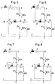
- FIG. 1a shows a single-quadrant DC chopper with energy transport from the network to the inverter.
- the contact wire 1 is connected via a filter choke LF to a connection point A, at which an automatically erasable semiconductor switch G1 and an input partial capacitance CFO are located.
- CFO is connected to a connection point B, at which an actuator choke LST, an input partial capacitance CFU and the positive DC connection of the inverter WR are located.
- G1 is connected to a connection point D, at which the further connection of LST and a diode D2 are located.
- CFU, D2 and the negative DC connection of WR are on the other hand via a connection point C on the wheel / rail system 2.
- WR is connected on the three-phase side (alternating connections) to a three-phase machine 3 (drive motor for rail vehicle).
- the voltage at CFO is UFO and the voltage at CFU is UFU.
- UFU UD
- FIG. 1b shows a two-quadrant DC chopper with energy transport in both directions.
- a diode D1 is parallel to G1 and an automatically erasable semiconductor switch G2 is parallel to D2.
- G1 is parallel to G1
- G2 is parallel to D2.
- FIG. 2a there is a single-quadrant DC chopper with energy transport from the network to the inverter for generation shown a higher DC link voltage.
- D1 lies between A and D and G2 lies between D and C.
- the positive DC connection of WR is connected to A.
- the contact wire 1 is connected to B via LF.
- FIG. 2b shows a two-quadrant DC chopper with energy transport in both directions for a higher intermediate circuit voltage.
- G1 are parallel to D1 and D2 are parallel to G2. The rest of the arrangement is as described under Figure 2a.
- FIG. 3a shows a two-quadrant direct current controller (3-point controller circuit) with energy transport in both directions.
- the contact wire 1 is connected via LF to A of the basic arrangement CFO / CFU / LST and the positive DC connection of WR is connected to B.
- G1 / D1 is the parallel connection of a further automatically erasable semiconductor switch G3 with a diode D3 between A and D in series.
- G2, G4 in turn automatically erasable semiconductor switches and D2, D4 denote diodes.
- connection point labeled E between G1 / D1 and G3 / D3 is connected via a diode D5 and the connection point labeled F between G2 / D2 and G4 / D4 is connected to B via a diode D6.
- the direct current regulator according to FIG. 3a is suitable for high input voltages.
- FIG. 3b shows a two-quadrant DC chopper (also composed of three identical 2-point chopper circuits) that is also suitable for high input voltages and has energy transport in both directions.
- the automatically erasable semiconductor switches G5 and G6 are parallel to D5 and D6. The rest of the arrangement and the advantages are as described under Figure 3a.
- FIG. 4a shows a brake branch with semiconductor switches that cannot be automatically erased, as can be inserted in parallel with LST in all circuits between D and B as required.
- the braking branch consists of two anti-parallel semiconductor switches T1, T2 (thyristors) with a braking resistor RB arranged in series.
- FIG. 4b shows a brake branch with an automatically erasable semiconductor switch, as can be inserted in parallel with CFU in all circuits between B and C and in addition in parallel with CFO between A and B if necessary.
- the brake branch consists of an automatic Erasable semiconductor switch G7 with braking resistor RB in series.
- the input capacitance consists of the series connection of two capacitors CFO and CFU.
- the capacitance which is connected to ground on one side, is kept at a fixed, predetermined constant value by a DC control circuit and the control choke LST.
- UD UFU + UFO.
- the converter circuit can be an arrangement with a two-point circuit (see FIGS. 1a or 1b).
- the 3-point circuit shown in FIGS. 3a and 3b is suitable for higher voltages UFU + UFO.
- a 3-point circuit according to Figure 3b which is composed of three 2-point phases.
- this basic circuit can be regrouped by switching devices so that it works as an input actuator (4q-S) on the AC contact wire (see Figure 17).
- a braking resistor RB between the output of the DC chopper D and the division point B of the input capacitance, which can be switched on via non-automatically erasable semiconductors (thyristors) T1, T2 and thereby sets the ratio of the two partial voltages UFO and UFU.
- Separate brake branches according to FIG. 4b with automatically erasable semiconductors G7 can be connected in parallel to the capacitance CFU or to both capacitances CFU and CFO.
- DC regulator circuits with a corresponding smoothing inductor LST can be connected in parallel at points A, B and C.
- the DC controllers / 4q-S are connected in parallel at points A / B1 or B2 / C (see Figure 17).
- the additional transformer windings and converter chokes required for multi-system operation are connected to the input actuators connected in parallel via switching devices.
- the current over LF is iF
- the current over WR is iD
- the current over LST is iST.
- the inductance of LST is L.
- the energy is transported from the grid to the consumers via the inverter.
- the DC chopper works as a buck converter.
- a constant and smaller intermediate circuit voltage UD UFU is generated from the variable input voltage Unet. As shown in Figures 5 to 8, three switching states can be distinguished.
- G1 and G3 are conductive.
- the voltage UFO is at LST.
- the converter works as a step-up converter.
- LST is magnetized by UFU (switching state according to FIG. 8 with a changed current direction shown in dashed lines).
- the switch to the switching state according to FIG. 7 takes place (with the current direction drawn in dashed lines).
- the current iST can flow freely via G2 and D6.
- the switching state according to FIG. 6 is achieved by deleting G2 (with the direction of the current drawn in dashed lines), with a current flow via D3 and D1.
- a brake branch T1 / T2 / RB is connected in parallel with LST.
- the special feature of this braking branch is that it consists of one or two braking resistors (a braking resistor is assigned to each semiconductor switch T1, T2) and two semiconductors T1, T2 that cannot be automatically erased. These semiconductors that cannot be automatically erased are automatically erased when G1, G3 or D1, D3 (deletion of T2) or G2, G4 or D2, D4 (deletion of T1) become conductive.
- the advantage of this brake branch according to FIG. 4a is the low circuit complexity compared to one or two brake branches, which are equipped with automatically erasable semiconductor switches and monitoring devices and are arranged in parallel with the CFO or in parallel with the CFU (see FIG. 4b).
- the mode of operation of the brake branch according to FIG. 4a used in the circuit according to FIG. 3a is described below with reference to FIGS. 8 to 16.
- the current over RB is iRB.
- the current iST flows in the actuator choke LST according to the counting arrows. Ignition of G2 and G4 results in the equivalent image according to FIG. 8 with a changed current supply (indicated by dashed lines), the inductor LST is magnetized.
- T2 can be ignited simultaneously with G2 and G4 or delayed accordingly (see Figure 9).
- the total current iRB + iST flows via G2 and G4.
- the choke current iST flows in freewheeling via G2 and D6 without counter voltage.
- LRB are parasitic inductors or di / dt limiting chokes and R denotes the ohmic resistance value of RB.
- T1 as well as G1 and G3 can be switched on with a delay, so that the equivalent circuit diagram according to FIG. 13 is achieved.
- an equivalent circuit diagram according to FIG. 14 results, provided iST ⁇ R ⁇ UFO. If the expression iSt ⁇ R> UFO, the equivalent circuit diagram according to FIG. 13 remains valid. After a defined minimum time after deleting G3, G2 may be ignited and the equivalent circuit diagram according to FIG. 15 results. The defined deletion of T1 takes place after igniting G4 (FIG. 16). Immediately after deletion of T1, its close season begins.
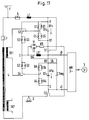
- the circuit shown in FIG. 17 shows a multi-system-compatible basic circuit for operation on (in particular 3 kV) direct current contact wire and on single-phase alternating current contact wire and is based on the circuit according to FIG. 3 b.
- the Circuit is modified in that the connection between CFO and B can be separated by means of a first switching device S1 (B is split into B1, B2), the connection between C and the wheel / rail system 2 can be separated by means of a second switching device S2 of a third switching device S3 the connection between E and G3 / D3 can be disconnected, by means of a fourth switching device S4 the connection between F and G2 / D2 can be disconnected, by means of a fifth switching device S5 the connection between LST and D can be disconnected and by means of a sixth switching device S6 an additional suction circuit capacitor CSaug can be connected in parallel to the CFU.
- a first switching device S1 B is split into B1, B2
- the connection between C and the wheel / rail system 2 can be separated by
- the contact positions of the switching devices S1 ... S6 shown in Figure 17 show the grouping on the 3kV direct current wire.
- the contact wire 1 is connected to LF via a main switch 5 for direct current feeding.
- Another main switch 7 connected to the contact wire 1 for alternating current feed is opened.
- S1 ... S5 are switched in such a way that the circuit configuration according to FIG. 3b including the brake branch according to FIG. 4a results.
- S6 is closed to achieve the parallel connection of UFU and CSaug.
- the connection points B1, B2 are connected to one another via S1 and correspond to B according to FIG.
- a brake branch T1 / T2 / RB is arranged between B1 and D.
- one or two separate branches in accordance with FIG. 4b can be used as brake branches parallel to the CFU and / or CFO.
- the CFU and CFO are connected in parallel and together form the DC link capacity at which the inverter is located.
- the transformer secondary winding TR1 is connected to the AC inputs E and F.
- the suction circuit is tuned to twice the mains frequency and absorbs the pendulum power caused by the 4q-S input rectification G1 / D1, G5 / D5, G6 / D6, G4 / D4.
- the branch G3, T1, RB can be used as a braking branch on the AC contact wire.
- the circuit is designed so that as many components as possible can be used for both systems. If components are only required for one system, some switching devices, e.g. S3 and S6 are eliminated. Switchgear S3 can be omitted if the brake branch is not required for operation on the AC contact wire. G3, D3, one side of the transformer secondary winding TR1 and point E are then firmly connected.
- the parallel-connected DC choppers / 4q-S are connected directly to points A / B1 or B2 / C.
- the additional transformer secondary windings TR2 ... and actuator chokes are connected to the parallel connected input converters via separate switching devices S3 ', S4' and S5 '(not shown).
Landscapes
- Engineering & Computer Science (AREA)
- Power Engineering (AREA)
- Life Sciences & Earth Sciences (AREA)
- Sustainable Development (AREA)
- Sustainable Energy (AREA)
- Transportation (AREA)
- Mechanical Engineering (AREA)
- Physics & Mathematics (AREA)
- Nonlinear Science (AREA)
- Electromagnetism (AREA)
- General Physics & Mathematics (AREA)
- Radar, Positioning & Navigation (AREA)
- Automation & Control Theory (AREA)
- Electric Propulsion And Braking For Vehicles (AREA)
- Rectifiers (AREA)
- Control Of Electrical Variables (AREA)
Claims (10)
- Ensemble convertisseur, qui fonctionne comme convertisseur direct de courant continu, pour l'alimentation d'un circuit intermédiaire en courant continu pour un consommateur de courant continu, en particulier un onduleur d'impulsions d'un réseau à courant continu, caractérisé en ce qu'entre le branchement positif (1) au réseau et le branchement négatif (2) au réseau, une première (CFo) et une deuxième capacité partielle (CFu) d'entrée sont montées en série, un self du convertisseur (LST) et le branchement positif au courant continu d'un consommateur de courant continu (WR) étant reliés au point de connexion (B) et en ce que le self du convertisseur est relié d'autre part par un premier interrupteur (G1) à semi-conducteurs pouvant se bloquer automatiquement à la première capacité partielle d'entrée et par une deuxième diode (D2) à la deuxième capacité partielle d'entrée, à laquelle le branchement négatif au courant continu du consommateur de courant continu est également relié (figure 1a).
- Ensemble convertisseur selon la revendication 1, caractérisé en ce qu'une première diode (D1) est mise tête-bêche avec premier interrupteur (G1) à semi-conducteurs pouvant se bloquer automatiquement et une deuxième diode (D2) avec un deuxième interrupteur (G2) à semi-conducteurs pouvant se bloquer automatiquement.
- Ensemble convertisseur selon la revendication 2, caractérisé en ce que le montage tête-bêche d'un troisième interrupteur (G3) à semi-conducteurs pouvant se bloquer automatiquement et d'une troisième diode (D3) sont montés en série avec le premier montage tête-bêche et le montage tête-bêche d'un quatrième interrupteur (G4) à semi-conducteurs pouvant se bloquer automatiquement et d'une quatrième diode (D4) avec le deuxième montage tête-bêche, le point de connexion (B) des capacités partielles (CFo, CFu) étant relié par une cinquième diode (D5) avec le point de connexion du premier et du troisième montage tête-bêche et par une sixième diode (D6) avec le point de connexion du deuxième et du quatrième montage tête-bêche (figure 3a).
- Ensemble convertisseur selon la revendication 3, caractérisé en ce qu'un cinquième (G5) ou un sixième interrupteur (G6) à semi-conducteurs pouvant se bloquer automatiquement sont mis tête-bêche avec une cinquième (D5) ou une sixième diode (D6) (figure 3b).
- Ensemble convertisseur, qui fonctionne comme convertisseur direct de courant continu, pour l'alimentation d'un circuit intermédiaire en courant continu pour un consommateur de courant continu, en particulier un onduleur d'impulsions d'un réseau à courant continu, caractérisé en ce que le branchement positif au réseau (1) se trouve au point de connexion (B) d'une première (CFo) et d'une deuxième capacité partielle (CFu) d'entrée, en ce que ce point de connexion est connecté par un self du convertisseur (LST) et une première diode (D1) à l'autre branchement de la première capacité partielle d'entrée et au branchement positif au courant continu du consommateur de courant continu (WR) et en ce que ce point de connexion est en outre connecté par ce self du convertisseur et un deuxième interrupteur (G2) à semi-conducteurs pouvant se bloquer automatiquement à l'autre branchement de la deuxième capacité partielle d'entrée, au branchement négatif au courant continu du consommateur de courant continu et au branchement négatif au réseau (figure 2a).
- Ensemble convertisseur selon la revendication 5, caractérisé en ce qu'un premier interrupteur (Gl) à semi-conducteurs pouvant se bloquer automatiquement est mis tête-bêche avec une première diode (D1) et une deuxième diode (D2) est mise tête-bêche avec le deuxième interrupteur (G2) à semi-conducteurs pouvant se bloquer automatiquement (figure 2a).
- Ensemble convertisseur selon la revendication 3 ou 4, caractérisé en ce que pour un système à polycourant avec possibilité de raccordement au réseau de courant continu et de courant alternatif, un tel regroupement est effectué à l'aide d'appareils de commutation (S1 ... S6), en ce que quatre montages constitués chacun d'un interrupteur à semi-conducteurs pouvant se bloquer automatiquement et d'une diode mis tête-bêche forment un convertisseur d'entrée à quatre quarts de cercle, tandis que les capacités partielles (CFo, CFu) d'entrée montées en parallèles sont réunies pour former la capacité du circuit intermédiaire.
- Ensemble convertisseur selon la revendication 7, caractérisé en ce que le montage en série du self du convertisseur (LST) avec un condensateur (CSaug) de circuit d'absorption forme un circuit d'absorption.
- Ensemble convertisseur selon une des revendications 1 à 8, caractérisé par un circuit de freinage, constitué d'une résistance de freinage (RB) montée en série avec de deux interrupteurs (T1, T2) à semi-conducteurs pouvant se bloquer automatiquement et mis tête-bêche, parallèle au self du convertisseur (LST).
- Ensemble convertisseur selon une des revendications 1 à 9, caractérisé par une résistance de freinage (RB), montée en série avec un interrupteur (G7) à semi-conducteurs pouvant se bloquer automatiquement, parallèle à au moins une capacité partielle (CFo et/ou CFu) d'entrée.
Applications Claiming Priority (2)
| Application Number | Priority Date | Filing Date | Title |
|---|---|---|---|
| DE4325275 | 1993-07-28 | ||
| DE4325275A DE4325275A1 (de) | 1993-07-28 | 1993-07-28 | Stromrichterschaltung zur Speisung eines Gleichspannungszwischenkreises |
Publications (2)
| Publication Number | Publication Date |
|---|---|
| EP0637121A1 EP0637121A1 (fr) | 1995-02-01 |
| EP0637121B1 true EP0637121B1 (fr) | 1996-11-20 |
Family
ID=6493887
Family Applications (1)
| Application Number | Title | Priority Date | Filing Date |
|---|---|---|---|
| EP94111470A Expired - Lifetime EP0637121B1 (fr) | 1993-07-28 | 1994-07-22 | Ensemble de convertisseur pour l'alimentation d'un circuit intermédiaire en courant continu |
Country Status (4)
| Country | Link |
|---|---|
| EP (1) | EP0637121B1 (fr) |
| DE (2) | DE4325275A1 (fr) |
| ES (1) | ES2097581T3 (fr) |
| PL (1) | PL174478B1 (fr) |
Families Citing this family (7)
| Publication number | Priority date | Publication date | Assignee | Title |
|---|---|---|---|---|
| DE19712564C1 (de) * | 1997-03-25 | 1998-06-25 | Siemens Ag | Schaltungsanordnung |
| DE19849763C1 (de) * | 1998-10-28 | 2000-03-02 | Siemens Ag | Betriebsverfahren für ein elektrisch angetriebenes Schienenfahrzeug |
| DE102005041825A1 (de) * | 2005-09-02 | 2007-03-15 | Siemens Ag | Regelvorrichtung für eine dreiphasige Drehstrommaschine |
| DE102011087153A1 (de) * | 2011-11-25 | 2013-05-29 | Converteam Gmbh | Mehrpunkt-Stromrichter mit Bremschopper |
| DE102017106770B4 (de) * | 2017-03-29 | 2023-10-05 | Kiepe Electric Gmbh | Schaltungsanordnung zum Schutz vor Netzüberspannungen für Stromrichter von Fahrzeugen, insbesondere von fahrleitungsgebundenen Fahrzeugen |
| CN112821791B (zh) * | 2021-02-02 | 2022-08-05 | 张超 | 一种直流降半压四象限整流器 |
| CN113315404B (zh) * | 2021-05-28 | 2022-05-27 | 张超 | 一种双直-双交对称型四象限变流器 |
Family Cites Families (11)
| Publication number | Priority date | Publication date | Assignee | Title |
|---|---|---|---|---|
| DE2800928C3 (de) * | 1978-01-10 | 1982-01-21 | Siemens AG, 1000 Berlin und 8000 München | Schaltungsanordnung für den Fahrbetrieb sowie für den Nutz- und Widerstandsbremsbetrieb einer aus einem Gleichspannungsnetz gespeisten Wechselstrommaschine |
| IT1118548B (it) * | 1979-04-04 | 1986-03-03 | Wabco Westinghouse Spa | Convertitore statico autorisonante a regolazione estesa |
| SU1417140A1 (ru) * | 1986-10-20 | 1988-08-15 | Уфимский авиационный институт им.Серго Орджоникидзе | Статический преобразователь с защитой |
| DE3724526A1 (de) * | 1987-07-24 | 1989-02-02 | Asea Brown Boveri | Stromrichterschaltung zur speisung eines gleichspannungs-zwischenkreises |
| DE3817652A1 (de) * | 1988-05-25 | 1989-12-07 | Asea Brown Boveri | Elektrisch betriebenes schienentriebfahrzeug mit mindestens zwei antriebsanlagen |
| DE3826283C2 (de) * | 1988-07-30 | 1996-12-19 | Licentia Gmbh | Netzstromrichter für einen Mehrsystem-Triebzug |
| EP0383971A1 (fr) * | 1989-02-22 | 1990-08-29 | Siemens Aktiengesellschaft | Circuit d'alimentation pour une locomotive à système multiple |
| DE3915211A1 (de) * | 1989-05-05 | 1990-11-08 | Licentia Gmbh | Schaltungsanordnung fuer an fahrdrahtspannungen verschiedener systeme betreibbare mehrsystemfahrzeuge |
| SU1729843A1 (ru) * | 1990-04-18 | 1992-04-30 | Московский Институт Инженеров Железнодорожного Транспорта | Электропривод транспортного средства |
| DE4042377C2 (de) * | 1990-04-27 | 1996-11-14 | Baumueller Nuernberg Gmbh | Elektrische Antriebseinrichtung für ein Fahrzeug |
| JPH084829B2 (ja) * | 1992-05-27 | 1996-01-24 | 寿産業株式会社 | H形鋼用ガイドを圧延機に取付ける方法及びこのガイド |
-
1993
- 1993-07-28 DE DE4325275A patent/DE4325275A1/de not_active Withdrawn
-
1994
- 1994-07-22 EP EP94111470A patent/EP0637121B1/fr not_active Expired - Lifetime
- 1994-07-22 DE DE59401070T patent/DE59401070D1/de not_active Expired - Fee Related
- 1994-07-22 ES ES94111470T patent/ES2097581T3/es not_active Expired - Lifetime
- 1994-07-25 PL PL94304445A patent/PL174478B1/pl unknown
Also Published As
| Publication number | Publication date |
|---|---|
| DE59401070D1 (de) | 1997-01-02 |
| DE4325275A1 (de) | 1995-02-02 |
| EP0637121A1 (fr) | 1995-02-01 |
| ES2097581T3 (es) | 1997-04-01 |
| PL174478B1 (pl) | 1998-08-31 |
| PL304445A1 (en) | 1995-02-06 |
Similar Documents
| Publication | Publication Date | Title |
|---|---|---|
| EP0832006B1 (fr) | Systeme convertisseur haute tension | |
| EP3718201B1 (fr) | Composant redresseur et module semi-conducteur d'un composant redresseur | |
| DE19857645A1 (de) | Elektrisches System für Elektrofahrzeug | |
| EP2596980B1 (fr) | Convertisseur de courant à plusieurs points avec hacheur de freinage | |
| DE102014103566A1 (de) | Elektrisches antriebssystem | |
| DE102018216236B4 (de) | Ladeschaltung für einen fahrzeugseitigen elektrischen Energiespeicher | |
| DE102018221519B4 (de) | Fahrzeugseitige Ladevorrichtung | |
| DE102012216691A1 (de) | Stromrichterschaltung und Verfahren zur Steuerung der Stromrichterschaltung | |
| EP0637121B1 (fr) | Ensemble de convertisseur pour l'alimentation d'un circuit intermédiaire en courant continu | |
| EP3290254A1 (fr) | Convertisseur de reseau de bord bidirectionnel et son procede de fonctionnement | |
| EP2728735A2 (fr) | Convertisseur de traction modulaire avec accumulateur d'énergie pour fournir une tension de circuit intermédiaire et procédé d'operation | |
| DE102018210781A1 (de) | Fahrzeugseitige Ladeschaltung | |
| DE102018216233A1 (de) | Ladeschaltung für einen fahrzeugseitigen elektrischen Energiespeicher | |
| EP0952030B1 (fr) | Circuit électrique d'alimentation pour un système d'entraînement électrique | |
| DE9403447U1 (de) | Energieversorgungseinrichtung für Reisezugwagen | |
| DE3832442A1 (de) | Vorrichtung zum betreiben elektrischer verbraucher eines reisezugwagens | |
| DE19702132C1 (de) | Einspeiseschaltung für ein Bordnetz eines Mehrsystemfahrzeugs | |
| DE102012206801A1 (de) | Schaltung mit einer stromrichterschaltung und verfahren zur leistungsanpassung | |
| DE102013212692A1 (de) | Energiespeichereinrichtung mit Gleichspannungsversorgungsschaltung | |
| DE2800928C3 (de) | Schaltungsanordnung für den Fahrbetrieb sowie für den Nutz- und Widerstandsbremsbetrieb einer aus einem Gleichspannungsnetz gespeisten Wechselstrommaschine | |
| EP0743744A2 (fr) | Convertisseur de courant | |
| WO2000051839A1 (fr) | Circuit d'injection sans transformateur pour wagons de chemin de fer | |
| DE102014203404A1 (de) | Stromrichterschaltung und Verfahren zum Betreiben derselben | |
| DE102017219985A1 (de) | Stromrichterkomponente und Halbleitermodul einer solchen Stromrichterkomponente | |
| DE2614445C2 (de) | Stromrichteranordnung zur Umformung einer vorgegebenen Netzwechselspannung |
Legal Events
| Date | Code | Title | Description |
|---|---|---|---|
| PUAI | Public reference made under article 153(3) epc to a published international application that has entered the european phase |
Free format text: ORIGINAL CODE: 0009012 |
|
| AK | Designated contracting states |
Kind code of ref document: A1 Designated state(s): BE DE ES IT |
|
| 17P | Request for examination filed |
Effective date: 19950705 |
|
| GRAG | Despatch of communication of intention to grant |
Free format text: ORIGINAL CODE: EPIDOS AGRA |
|
| GRAH | Despatch of communication of intention to grant a patent |
Free format text: ORIGINAL CODE: EPIDOS IGRA |
|
| 17Q | First examination report despatched |
Effective date: 19960412 |
|
| GRAH | Despatch of communication of intention to grant a patent |
Free format text: ORIGINAL CODE: EPIDOS IGRA |
|
| GRAA | (expected) grant |
Free format text: ORIGINAL CODE: 0009210 |
|
| AK | Designated contracting states |
Kind code of ref document: B1 Designated state(s): BE DE ES IT |
|
| REF | Corresponds to: |
Ref document number: 59401070 Country of ref document: DE Date of ref document: 19970102 |
|
| ITF | It: translation for a ep patent filed | ||
| REG | Reference to a national code |
Ref country code: ES Ref legal event code: FG2A Ref document number: 2097581 Country of ref document: ES Kind code of ref document: T3 |
|
| PLBE | No opposition filed within time limit |
Free format text: ORIGINAL CODE: 0009261 |
|
| STAA | Information on the status of an ep patent application or granted ep patent |
Free format text: STATUS: NO OPPOSITION FILED WITHIN TIME LIMIT |
|
| 26N | No opposition filed | ||
| PGFP | Annual fee paid to national office [announced via postgrant information from national office to epo] |
Ref country code: BE Payment date: 19980616 Year of fee payment: 5 |
|
| PGFP | Annual fee paid to national office [announced via postgrant information from national office to epo] |
Ref country code: ES Payment date: 19980730 Year of fee payment: 5 Ref country code: DE Payment date: 19980730 Year of fee payment: 5 |
|
| PG25 | Lapsed in a contracting state [announced via postgrant information from national office to epo] |
Ref country code: ES Free format text: LAPSE BECAUSE OF NON-PAYMENT OF DUE FEES Effective date: 19990723 |
|
| PG25 | Lapsed in a contracting state [announced via postgrant information from national office to epo] |
Ref country code: BE Free format text: LAPSE BECAUSE OF NON-PAYMENT OF DUE FEES Effective date: 19990731 |
|
| BERE | Be: lapsed |
Owner name: ABB PATENT G.M.B.H. Effective date: 19990731 |
|
| PG25 | Lapsed in a contracting state [announced via postgrant information from national office to epo] |
Ref country code: DE Free format text: LAPSE BECAUSE OF NON-PAYMENT OF DUE FEES Effective date: 20000503 |
|
| REG | Reference to a national code |
Ref country code: ES Ref legal event code: FD2A Effective date: 20000810 |
|
| PG25 | Lapsed in a contracting state [announced via postgrant information from national office to epo] |
Ref country code: IT Free format text: LAPSE BECAUSE OF NON-PAYMENT OF DUE FEES;WARNING: LAPSES OF ITALIAN PATENTS WITH EFFECTIVE DATE BEFORE 2007 MAY HAVE OCCURRED AT ANY TIME BEFORE 2007. THE CORRECT EFFECTIVE DATE MAY BE DIFFERENT FROM THE ONE RECORDED. Effective date: 20050722 |