EP0636778B1 - Verfahren und Vorrichtung zum korrigieren der Kraftstoffeinspritzungsdauer in Abhängigkeit des Durchflusses einer Tankentlüftungsanlage für einen Einspritzmotor - Google Patents
Verfahren und Vorrichtung zum korrigieren der Kraftstoffeinspritzungsdauer in Abhängigkeit des Durchflusses einer Tankentlüftungsanlage für einen Einspritzmotor Download PDFInfo
- Publication number
- EP0636778B1 EP0636778B1 EP19940401644 EP94401644A EP0636778B1 EP 0636778 B1 EP0636778 B1 EP 0636778B1 EP 19940401644 EP19940401644 EP 19940401644 EP 94401644 A EP94401644 A EP 94401644A EP 0636778 B1 EP0636778 B1 EP 0636778B1
- Authority
- EP
- European Patent Office
- Prior art keywords
- engine
- coefficient
- injection
- richness
- adaptation
- Prior art date
- Legal status (The legal status is an assumption and is not a legal conclusion. Google has not performed a legal analysis and makes no representation as to the accuracy of the status listed.)
- Expired - Lifetime
Links
- 238000002347 injection Methods 0.000 title claims description 90
- 239000007924 injection Substances 0.000 title claims description 90
- 238000010926 purge Methods 0.000 title claims description 66
- 239000000446 fuel Substances 0.000 title claims description 63
- 238000000034 method Methods 0.000 title claims description 34
- 238000012937 correction Methods 0.000 claims description 34
- 230000006978 adaptation Effects 0.000 claims description 26
- 230000007704 transition Effects 0.000 claims description 23
- 239000000523 sample Substances 0.000 claims description 14
- QVGXLLKOCUKJST-UHFFFAOYSA-N atomic oxygen Chemical compound [O] QVGXLLKOCUKJST-UHFFFAOYSA-N 0.000 claims description 13
- 239000000203 mixture Substances 0.000 claims description 13
- 229910052760 oxygen Inorganic materials 0.000 claims description 13
- 239000001301 oxygen Substances 0.000 claims description 13
- 238000004364 calculation method Methods 0.000 claims description 10
- 125000004122 cyclic group Chemical group 0.000 claims description 7
- 239000007789 gas Substances 0.000 claims description 6
- 239000000110 cooling liquid Substances 0.000 claims 1
- 230000006870 function Effects 0.000 description 21
- 239000003570 air Substances 0.000 description 12
- 230000007423 decrease Effects 0.000 description 7
- 238000009434 installation Methods 0.000 description 5
- 230000000295 complement effect Effects 0.000 description 3
- 239000002826 coolant Substances 0.000 description 3
- 239000007788 liquid Substances 0.000 description 3
- 238000012544 monitoring process Methods 0.000 description 3
- 239000000047 product Substances 0.000 description 3
- 239000012080 ambient air Substances 0.000 description 2
- 230000003197 catalytic effect Effects 0.000 description 2
- 239000004020 conductor Substances 0.000 description 2
- 238000011161 development Methods 0.000 description 2
- 230000000694 effects Effects 0.000 description 2
- 238000011084 recovery Methods 0.000 description 2
- 238000011144 upstream manufacturing Methods 0.000 description 2
- OKTJSMMVPCPJKN-UHFFFAOYSA-N Carbon Chemical compound [C] OKTJSMMVPCPJKN-UHFFFAOYSA-N 0.000 description 1
- 239000004215 Carbon black (E152) Substances 0.000 description 1
- 230000002745 absorbent Effects 0.000 description 1
- 239000002250 absorbent Substances 0.000 description 1
- 230000033228 biological regulation Effects 0.000 description 1
- 229910052799 carbon Inorganic materials 0.000 description 1
- 238000006243 chemical reaction Methods 0.000 description 1
- 238000002485 combustion reaction Methods 0.000 description 1
- 238000001816 cooling Methods 0.000 description 1
- 239000000498 cooling water Substances 0.000 description 1
- 230000003247 decreasing effect Effects 0.000 description 1
- 230000001934 delay Effects 0.000 description 1
- 238000001514 detection method Methods 0.000 description 1
- 238000010586 diagram Methods 0.000 description 1
- 230000037213 diet Effects 0.000 description 1
- 235000005911 diet Nutrition 0.000 description 1
- 239000002828 fuel tank Substances 0.000 description 1
- 229930195733 hydrocarbon Natural products 0.000 description 1
- 150000002430 hydrocarbons Chemical class 0.000 description 1
- 230000010354 integration Effects 0.000 description 1
- 238000012886 linear function Methods 0.000 description 1
- 238000013507 mapping Methods 0.000 description 1
- 230000015654 memory Effects 0.000 description 1
- 238000002156 mixing Methods 0.000 description 1
- 229910052757 nitrogen Inorganic materials 0.000 description 1
- 229910052698 phosphorus Inorganic materials 0.000 description 1
- 230000000750 progressive effect Effects 0.000 description 1
- 230000001105 regulatory effect Effects 0.000 description 1
- 239000013589 supplement Substances 0.000 description 1
- XLYOFNOQVPJJNP-UHFFFAOYSA-N water Substances O XLYOFNOQVPJJNP-UHFFFAOYSA-N 0.000 description 1
Images


Classifications
-
- F—MECHANICAL ENGINEERING; LIGHTING; HEATING; WEAPONS; BLASTING
- F02—COMBUSTION ENGINES; HOT-GAS OR COMBUSTION-PRODUCT ENGINE PLANTS
- F02M—SUPPLYING COMBUSTION ENGINES IN GENERAL WITH COMBUSTIBLE MIXTURES OR CONSTITUENTS THEREOF
- F02M25/00—Engine-pertinent apparatus for adding non-fuel substances or small quantities of secondary fuel to combustion-air, main fuel or fuel-air mixture
- F02M25/08—Engine-pertinent apparatus for adding non-fuel substances or small quantities of secondary fuel to combustion-air, main fuel or fuel-air mixture adding fuel vapours drawn from engine fuel reservoir
-
- F—MECHANICAL ENGINEERING; LIGHTING; HEATING; WEAPONS; BLASTING
- F02—COMBUSTION ENGINES; HOT-GAS OR COMBUSTION-PRODUCT ENGINE PLANTS
- F02D—CONTROLLING COMBUSTION ENGINES
- F02D41/00—Electrical control of supply of combustible mixture or its constituents
- F02D41/0025—Controlling engines characterised by use of non-liquid fuels, pluralities of fuels, or non-fuel substances added to the combustible mixtures
- F02D41/003—Adding fuel vapours, e.g. drawn from engine fuel reservoir
- F02D41/0045—Estimating, calculating or determining the purging rate, amount, flow or concentration
-
- F—MECHANICAL ENGINEERING; LIGHTING; HEATING; WEAPONS; BLASTING
- F02—COMBUSTION ENGINES; HOT-GAS OR COMBUSTION-PRODUCT ENGINE PLANTS
- F02B—INTERNAL-COMBUSTION PISTON ENGINES; COMBUSTION ENGINES IN GENERAL
- F02B75/00—Other engines
- F02B75/02—Engines characterised by their cycles, e.g. six-stroke
- F02B2075/022—Engines characterised by their cycles, e.g. six-stroke having less than six strokes per cycle
- F02B2075/027—Engines characterised by their cycles, e.g. six-stroke having less than six strokes per cycle four
-
- F—MECHANICAL ENGINEERING; LIGHTING; HEATING; WEAPONS; BLASTING
- F02—COMBUSTION ENGINES; HOT-GAS OR COMBUSTION-PRODUCT ENGINE PLANTS
- F02D—CONTROLLING COMBUSTION ENGINES
- F02D41/00—Electrical control of supply of combustible mixture or its constituents
- F02D41/0025—Controlling engines characterised by use of non-liquid fuels, pluralities of fuels, or non-fuel substances added to the combustible mixtures
- F02D41/003—Adding fuel vapours, e.g. drawn from engine fuel reservoir
- F02D41/0042—Controlling the combustible mixture as a function of the canister purging, e.g. control of injected fuel to compensate for deviation of air fuel ratio when purging
Definitions
- the invention relates to a method for correcting the injection time as a function of the purge flow of a circuit purge including a canister, for a combustion engine internal, of the spark-ignition type, fitted with an installation fuel supply by injection, and hereinafter referred to as an injection engine description, and preferably, but not exclusively, to four-stroke engine cycle.
- the power supply installation fuel of such an injection engine includes a engine air intake manifold, upstream of which one air flow control shutter, the most often disc-shaped, called a butterfly, is mounted rotating in a body.
- the injection system includes at least one injector delivering fuel into the intake manifold.
- the injector or each injector is supplied with fuel at a pressure given by a regulator, which drifts towards the injector part of the fuel it receives from the tank through a pump, and which returns the amount of excess fuel to the tank compared to that injected, which is a function of the duration of opening of the injector, called duration of injection, and determined by a computer connected to sensors engine operating parameters.
- the computer generally receives representative signals the water or coolant temperature of the engine, the air temperature in the intake manifold, the opening angle of the butterfly, and above all receives engine rotation signals from example by a sensor cooperating with a toothed wheel integral with the flywheel, and having a singularity, for example a missing tooth, to detect dead center top (P.M.H.) of a reference cylinder, allowing the calculator to determine the injection phases or times in the different cylinders, the engine speed being calculated from the signal modulated by scrolling teeth.
- the computer can also receive a signal from pressure measured directly in the intake manifold, or can calculate this pressure signal from two measures chosen from the group including the opening angle throttle, air flow and engine speed.
- This calculator which determines the instant and the duration each injector, is generally simultaneously an engine control computer, filling other command and control functions, and determining especially the moments of ignition of the cylinder plugs of the motor.
- a richness coefficient KO2 determined, in particular by applying transitions of value, depending on the richness signal of the probe oxygen in the engine operating areas while closed loop, and set equal to a nominal value within motor operation in open loop, for example example in low temperature operation (after starting the engine cold), or decelerating, or full load, and finally if the engine speed is greater than a given high threshold.
- the richness coefficient KO2 by the calculator can increase or reduce the duration basic injection, to center the operation of the engine on a wealth equal to 1.
- the injection duration basic as a substantially linear function increasing, in the useful operating range of the engine, absolute pressure in the intake manifold, representing the engine torque, i.e. the load of the engine, and neglecting correction coefficients from maps, for example according to engine speed, pressure in the tubing or opening angle of the butterfly, to translate the inflection of the right into a S curve, in areas of low and high pressure in the tubing.
- This substantially linear increasing function is represented by a line having a pressure offset at the origin, called offset, and a gain (or slope of the line) which are each drawn from a cartography, according to less engine speed.
- a canister containing means for absorbing fuel vapors.
- This canister is connected to the tank by a recovery line, is fitted with a vent putting the fuel tank into the air free and is connected to the intake circuit, preferably in downstream of the butterfly, by a suction line on which a control canister drain valve is fitted electric, the flow rate of which is controlled by the computer.
- the purge circuit thus produced allows, when the valve is open, and due to the depression prevailing downstream of the butterfly in the tubing, sucking in ambient air through the vent, through the canister, and thereby purge the canister the fuel it contains by mixing it with this ambient air so that it is sucked with it into the circuit of admission.
- Electrically operated purge valve is usually a frequency controlled solenoid valve constant, and whose control parameter is the ratio cyclical opening (R.C.O.) which is variable, i.e. that the opening time, for a constant period, corresponds to a variable fraction of this period, which corresponds to the length of the electrical current slot of command applied.
- the opening duty cycle is defined by a map based mainly on the pressure in the intake manifold and engine speed.
- the fuel supply by the injectors is ordered without explaining the content of fuel from the purge circuit, corresponding to the ratio of mass flow of fuel at total mass flow of purge circuit, and without ensuring continuous monitoring of the contribution of the purge circuit and the canister to the supply of the motor.
- mapping does not take into account the state of filling of the canister, and is therefore voluntarily limited at low flow rates to reduce the contribution of the canister, especially at low loads where the superabundant supply of fuel vapor vis-à-vis the motor need causes excessive coefficient drift KO2 wealth.
- the calculator calculates an injection duration, which is representative of engine requirements and actually applied to the injectors, without always taking into account all fuel inputs from the canister, and, on the other hand, that the flow of the canister purge valve is controlled without holding also does not account for the filling status of the canister.
- canister purge and self-adaptation offset and gain terms occur simultaneously, in all regimes: we adopt, as a term of self-adaptation, an idle shift when the engine is running at idle, and, except idle, an offset off slowed down at low pressures, where the influence of the offset is preponderant, and a gain at high pressure.
- the state is taken into account by the self-adaptation by the calculation of a purge offset, when purging is authorized.
- WO89 / 10472 proposes a method of correction of the injection time, depending on the flow of purging a canister purge circuit for a injection, in which the canister, collecting vapors of fuel from a tank, is connected to a engine intake manifold fitted with a shutter or air flow control butterfly, by a purge valve of the electrically controlled canister, the flow of which is controlled by a computer connected to sensors of parameters of engine operation, from which it receives at least engine rotation signals and signals for know the pressure in the intake manifold, as well than an oxygen sensor in the exhaust gases of the engine.
- the calculator calculates a representative injection time engine requirements (T inj M), obtained from a basic injection duration (T inj B) expressed using at least one map based at least on the regime engine, and corrected, on the one hand, taking into account a richness coefficient (KO2) to which we apply value transitions as a function of the richness signal of the oxygen sensor in the operating areas of the motor in closed loop, and fixed equal to a nominal value in the motor operating areas in a loop open, to ensure the centering of the operation of the engine on a wealth equal to 1, and, on the other hand, by a cyclic self-adaptation to ensure that the coefficient of wealth (KO2) remains close to its nominal value, by correction of any drift in the richness coefficient (KO2).
- K2 richness coefficient
- the correction method includes calculating a injection time (T inj A) applied to each injector of the engine by subtracting from the representative injection time motor requirements (T inj M) duration (TI CAN) corresponding to the contribution of the purge circuit expressed by the quantity of fuel equivalent to the contribution of vapors from the purge circuit between two consecutive injections, and calculating said amount of fuel by doing the product of the quantity of fuel air-vapor mixture controlled by the purge valve between said injections by a coefficient K CAN of estimation of the content of fuel from the purge circuit.
- T inj A injection time
- T inj M representative injection time motor requirements
- TI CAN duration
- This known method also includes a step consisting of to define said coefficient (K CAN) as applicable in all engine operating conditions, and developed continuously when purging is authorized, to from the drift of the richness coefficient (KO2), from so that K CAN is increased or decreased respectively if KO2 is lower or higher than its value respectively nominal, and to correct the coefficient K CAN either by a slow adaptation, to allow its fine adaptation and continuous, by application to the current value of K CAN a correction proportional to a deviation from the coefficient KO2 richness compared to its nominal value, i.e. by rapid adaptation after interruption of adaptation slow.
- the contribution of the canister and its circuit purge is thus continuously estimated from the single coefficient K CAN, which itself represents an estimate of the fuel content of the purge circuit, and that is defined from the drift of the richness coefficient KO2 when the engine is operating in a closed loop and the purge is active.
- K CAN can be used in all engine operating conditions, its intake in account can be substituted for that of the terms of idle offset in purge and idle offset under purge of the aforementioned known self-adaptation methods.
- the problem underlying the invention is to allow a good estimate of the fuel content of the purge circuit by good monitoring of the evolution of the coefficient K CAN.
- the method of the invention is characterized in that it consists, in slow adaptation of K CAN, to use, as deviation of proportional correction, the difference between the nominal value and an average value of KO2, the calculation of this correction being restarted after a predetermined number m of transitions of KO2, and, in rapid adaptation of K CAN, to apply to its current value a correction proportional to the deviation between the nominal value and the current value of the coefficient richness KO2, when the latter evolves without transition for a time greater than a predetermined threshold, then restart the calculation of the rapid correction of K CAN all n top dead centers, n being a number predetermined, as long as a KO2 transition is not obtained.
- the method includes determining the quantity of fuel air-vapor mixture controlled by the purge valve from the pressure difference at which the purge valve is subject to and the duration opening of this valve, since the previous injection, with reference to the flow characteristic of this valve, stored in the computer.
- the subtracting the TI CAN duration corresponding to said quantity of fuel air-vapor mixture controlled by the purge valve, can be provided twice, when two consecutive injection phases, so that during of the first injection, we order a first subtraction partial, defined by a percentage of said duration TI CAN, and during the second injection, we order a second partial subtraction, defined by the complement TI CAN duration.
- the process according to the invention further consists in memorizing the value of the coefficient K CAN when the engine stops (ignition off), and to adopt as value of the coefficient K CAN following a engine restart, said value memorized and corrected by a coefficient depending on the evolution of the state temperature of the vehicle during stop, this coefficient of correction may be a function of the temperature of the engine coolant.
- the process consists of preferably to allow the slow adaptation of K CAN only if mean KO2 value is outside of a dead band enrichment and a dead band of impoverishment, located on either side of the nominal value of KO2, and to take into account a possible mismatch of the first order, we adopt a dead band of enrichment whose width is greater than that of the dead band of impoverishment.
- the process according to the invention can consist in applying said proportional correction when the richness coefficient KO2 evolves without transition deviating from its nominal value for a time higher than said predetermined threshold, for example around 3 seconds.
- the method advantageously consists in interrupt the continuous development of K CAN in the zones of motor operation in open loop.
- it also consists in expressing the duration of injection of base (T inj B), for a given engine speed, like a substantially linear increasing function of pressure in the tubing, with an offset (D) at the origin and a gain (G) which are taken from maps according to less engine speed, and to ensure self-adaptation cyclic by self-adaptation of the offset (D) and the gain (G).
- the method can consist in expressing the quantities of fuel directly in mass and to be converted injection time at the end of the calculation chain through of a known characteristic quantity-duration of opening injector.
- the invention also relates to a device intended for implementing the process specific to the invention, and as presented above, using a calculator which includes at least one microprocessor, which is programmed and / or carried out in such a way as to control the progress of this process.
- FIG. 1 is schematically represented in 1, a four-stroke, four-cylinder injection engine, and positive ignition, equipped with an injection system indirect multi-point fuel.
- This installation includes four injectors 2 each mounted in one respectively of the four branches 3 downstream of a pipe intake 4, and each opening into the cylinder head engine 1, at the intake valve of a cylinder corresponding.
- An air flow control butterfly 5 intake is rotatably mounted in a throttle body 6 in the upstream part of the pipe 4, the throttle body 6 having a bypass pipe 7 on the butterfly 5, and whose passage section is regulated by a valve shown diagrammatically at 8 and controlled by a stepping motor 9.
- the injectors 2 are supplied with fuel under a pressure defined by the regulator 10, itself supplied from the reservoir 11, closed by a sealed cap, by via pump 12 on the supply line 13 on which the filter 14 is also mounted.
- the supplement the amount of fuel derived by the regulator 10 to injectors 2 is returned to the tank 11 through the return line 15.
- Fuel vapors forming in the tank 11 are collected by a canister 16, containing a absorbent charge of these vapors, for example carbon active, and connected to the tank by the recovery line 17.
- Canister 16 has a vent 18, through which it places in the open air the reservoir 11, and is connected to the tubing intake 4, downstream of the throttle valve 5 by a suction line 19 on which a valve is mounted 20 electrically operated, for purging the canister 16.
- This valve 20 is a solenoid valve normally closed at rest and opening controlled by R.C.O. variable.
- the R.C.O. variable of this valve 20, so the flow purging the canister 16 of the fuel vapors it contains, as well as the position of the electric stepper motor 9 are controlled by electrical commands which are transmitted from the computer 21 by the conductors 22 and 23. From even, the duration of opening or injection of the injectors 2, depending on the amount of fuel injected by each injector 2 in the corresponding cylinder, (since the pressure difference applied to injectors 2 is constant and fixed by the regulator 10), is controlled by electrical orders applied by the computer 21 to the injectors 2 by the conductor 24.
- injection duration R.C.O. variable, stepper motor control
- R.C.O. variable, stepper motor control electrical orders (injection duration, R.C.O. variable, stepper motor control) are developed by the computer 21 from signals received from different engine operating parameter sensors, one of which intake air temperature signal 25, issued by a temperature probe 26 placed in the air stream, a tubing absolute pressure signal 27 delivered by a pressure probe 28 in tubing 4, a signal from engine cooling water temperature 29 1 by a sensor not shown, and a rotation signal 30 engine, to determine the engine speed, as well as the passages at P.M.H. in the different cylinders for determining the instants of injection.
- This signal 30 can be provided by a sensor cooperating with a toothed wheel driven by the flywheel and having a singularity of detection of the transition to P.M.H. of a cylinder reference.
- the computer 21 also receives a signal 31 butterfly opening angle 5 supplied by a sensor suitable, such as a position feedback potentiometer angle of the butterfly 5, and mounted on the axis of rotation of the latter, and delivers at 33 a consumption signal of combustible. Finally, the computer 21 receives a signal at 32 of richness R delivered, in the form of electric voltage, by an oxygen probe called ⁇ probe, placed in the gases engine exhaust, of which it indicates the oxygen. In engine operation in closed loop, the richness signal R is used by the computer 21 for center engine operation on equal wealth to 1.
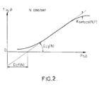
- the computer 21 first calculates a basic injection time, referring to a network of curves stored in the computer 21 and such that that shown in Figure 2, which gives for a diet constant engine given, the basic injection time T inj B as a function of the absolute pressure P tub in the pipe 4, this curve being, over most of the range of useful engine function, similar to a function increasing linear defined by a pressure shift at the origin D and by a gain G corresponding to the slope of the line representative of this function.
- D and G are each taken from a map based in particular on the regime motor N (functions f (N) and g (N)).
- the curve has rounded parts in S obtained from the right after multiplicative correction by a cartographic coefficient K carto, function in particular of the engine speed N, and of the pressure P tub or of the butterfly opening angle 5 (function h (N, P).
- the computer 21 then increases or reduces the injection duration applied to the injectors 2 to obtain a richness signal R equal to 1. For this, the computer 21 calculates a richness coefficient KO2 by which it multiplies the basic injection time T inj B given by the formula (1).
- the richness coefficient KO2 is chosen equal to 1. These zones correspond in particular to operation with a ⁇ probe broken, or with a lower air temperature at a closed loop entry threshold, for example in when the engine is cold started, or when the loop open is imposed by the regime or the opening angle of the throttle, for example when decelerating or at full load, or if the engine speed N is greater than a given high threshold, for example 4500 rpm, and generally speaking, each times the target wealth differs from 1.
- T inj M (P tub - D) x G x K carto x KO2
- T inj A T inj M - TI CAN
- TI CAN is expressed, which corresponds a decrease in the amount of fuel to be injected by compared to the calculated needs, as a function of the amount of fuel introduced as vapor between two consecutive injections, and coming from the purge.
- this amount is determined between P.M.H. of the current injection phase and the P.M.H. of the previous injection phase.
- the quantity of fuel equivalent to the intake in the form of steam from canister 16 and lines 17 and 19 of purge circuit, is calculated according to a content estimated purge system fuel and quantity fuel air-vapor mixture controlled by the fuel valve purge 20, between P.M.H. of the last two injections, this estimated content corresponding to the flow ratio mass of fuel at the total mass flow of the purge, and being defined using a coefficient K CAN, as described below.
- This quantity of air-vapor mixture Q a-v is determined from the opening time tR.C.O. of this valve 20 from the P.M.H. previous injection, pressure difference at which this valve 20 is subject, i.e. the difference between the pressure atmospheric P atm in the canister 16 in the open air by its vent 18, and the absolute pressure in the tubing P tub, and the flow characteristic of the purge circuit which is stored in the computer 21 as a function of the depression (P atm - P tub) in tubing 4 and at 100% of R.C.O. (full opening of valve 20).
- the flow rate of the valve 20 is representative of the quantity of air-vapor mixture admitted by the valve 20, per unit of time.
- Knowledge of P tub and duration tR.C.O. of valve 20 since the last injection therefore makes it possible to know Q a-v, of which TI CAN is a function.
- the amount of fuel equivalent to this intake can be considered subtracted twice, instead of of one, the first subtraction being defined as a percentage of this calculated equivalent quantity, and the second subtraction corresponding to the complement.
- the output 33 of the computer 21 is an output on which a consumption signal is given instantaneous, which corresponds to an integration of the signal T inj M.
- the fuel quantities have been expressed above, for example, in injection times, because the injector quantity-duration characteristic is known, but they can be expressed directly in mass, the conversion into injection time being done at the end of calculation chain, through this characteristic.
- the two upper curves in Figure 3 represent, as a function of time, an example of changes in correspondence of the richness signal R, as obtained at from the signal supplied by the oxygen sensor ⁇ , and from the richness coefficient KO2.
- this curve undulates around the value 1, which it takes at successive times T1 to T6.
- the computer 21 applies to KO2 a value transition corresponding to a positive step 35, followed by a gradual increase 36 until time T3 where, under the effect of the increase in the value of KO2, therefore injection time, and therefore the amount of fuel injected, R stops being less than 1 to become again greater than 1.
- the computer 21 then gives KO2 a new value transition, but this time in the form a negative step 37, in order to rapidly decrease its value, followed by a gradual decrease 38, to the instant T4, where R ceases to be greater than 1 to become again less than 1.
- the computer 21 gives KO2 a transition from value to positive step 39, followed by progressive increase 40 until time T5 where R becomes greater than 1, and so on.
- the contribution of canister 16 and its purge circuit 17, 19, 20 at the supply of engine 1 with fuel is considered to be expressed by an amount of fuel equivalent to the intake of fuel vapors delivered by valve 20.
- This equivalent quantity is calculated at each P.M.H. injection as being equal to product of the quantity of fuel air-vapor mixture, delivered by valve 20 from the P.M.H. injection previous, by a coefficient K CAN, corresponding to a estimated content of canister 16 and its circuit purge 17, 19, 20 of fuel vapor.
- the amount of fuel air-vapor mixture can be determined from the product of the difference of pressure to which valve 20 is subjected, by duration t R.C.O. of valve 20, with reference to the flow characteristic of this valve 20, stored in the computer 21 and for example tabulated at 100% R.C.O. (full opening), the aforementioned pressure difference being given by the difference between atmospheric pressure and P tub.
- K CAN is estimated in permanently from the evolution of KO2, if the installation operates in closed loop and valve 20 controls a flow purge.
- K CAN The principle of this adaptation of K CAN consists, by reference to the drift of the richness coefficient KO2 by compared to its nominal value 1, to be increased or respectively decrease the value of K CAN if KO2 is lower or respectively higher than its nominal value 1.
- this slow variation of K CAN is not authorized by the computer 21 only if the average value of KO2 is outside a so-called “dead” enrichment band and a so-called “dead” band of depletion, which extend on either side of the nominal value 1 of KO2, the width of the enrichment dead band being greater to that of the dead band of depletion, in order to hold account for a possible mismatch of the shift D and / or the gain G.
- K CAN is authorized for a difference between the mean value of the richness coefficient KO2 and its nominal value 1 which is representative of an enrichment higher than an enrichment threshold, corresponding to the width of the enrichment dead band, and by example of 3%, while the decrease in K CAN is allowed for a deviation between the mean value of KO2 and its nominal value 1 which is representative of a depletion above a depletion threshold, corresponding to the width of the depletion dead band, for example around 1.5%.
- K CAN On the lower curve of figure 3, which represents the evolution of K CAN, the value of K CAN is represented constant between T1 and T6, because we suppose that the predetermined number m of successive KO2 transitions, taken into account for the slow adaptation of K CAN, is greater to 6.
- the rapid correction is thus interrupted at the instant T12, corresponding to the transition 43 of KO2, when R becomes 1 again.
- time delay ⁇ 1T initiated at time T7 of signal KO2 crossing its nominal value 1, requires constant scrutiny of the difference between the value current of KO2 and its nominal value.
- time delay ⁇ 1T is replaced by a time delay ⁇ '1T, initiated at time T6 of the last transition 41 of K CAN, and flowing to instant T8, on condition that at this instant KO2 is noted diverge from its nominal value 1. Otherwise, we does not perform rapid correction of K CAN and relaunches the time delay ⁇ '1T.
- K CAN at restart is chosen equal to K CAN stored x 65/100, i.e. 0.65 K CAN stored.
- the computer 21 which is in fact a central computing and control unit, including calculation circuits, memories, counters, registers and other necessary regulation and control circuits and known structure, comprises at least one microprocessor or microcontroller programmed and / or produced so as to order the progress of this process.
Landscapes
- Engineering & Computer Science (AREA)
- Chemical & Material Sciences (AREA)
- Combustion & Propulsion (AREA)
- Mechanical Engineering (AREA)
- General Engineering & Computer Science (AREA)
- Electrical Control Of Air Or Fuel Supplied To Internal-Combustion Engine (AREA)
- Supplying Secondary Fuel Or The Like To Fuel, Air Or Fuel-Air Mixtures (AREA)
Claims (13)
- Verfahren zum Korrigieren der Einspritzdauer in Abhängigkeit des Spüldurchsatzes einer Spülleitung (16, 17, 19) mit Kanister (16) für einen Einspritzmotor (1), wobei der Kanister (16), welcher die von einem Tank (11) herrührenden Kraftstoffdämpfe sammelt, mit einem Ansaugkrümmer (4) des Motors (1), der mit einem Steuerveischluß oder einer Stellklappe (5) für den Luftdurchsatz versehen ist, über ein elektrisch gesteuertes Ventil zum Spülen des Kanisters (16) verbunden ist, dessen Durchsatz durch einen Rechner (21) geregelt wird, der mit Fühlern (26, 28) für Funktionsparameter des Motors (1), von welchen er zumindest Drehzahlsignale (30) des Motors und Signale (27, 3C, 31) empfängt, die den Druck (P tub) in dem Ansaugstutzen (4) mitteilen, sowie mit einer Sauerstoffsonde (32) in dem Motorabgas verbunden ist, wobei der Rechner (21) eine Einspritzdauer berechnet, die für den Bedarf (T inj M) des Motors repräsentativ ist und beginnend mit einer Basiseinspritzdauer (T inj B) erhalten wird, die mit Hilfe von zumindest einer Karte als Funktion der Motordrehzahl (N) ausgedrückt ist und einerseits korrigiert wird, indem ein Anreicherungskoeffizient (KO2) berücksichtigt wird, auf welchen Wertübergänge (35, 37, 41, 43) als Funktion des Anreicherungssignals (R) der Sauerstoffsonde (32) in den Funktionszonen des Motors (1) mit geschlossener Schleife angewendet werden, und der auf einen Nominalwert in den Funktionszonen des Motors (1) mit offener Schleife festgelegt ist, um die Zentrierung der Funktion des Motors (1) auf eine Anreicherung gleich 1 sicherzustellen, und andererseits durch eine zyklische Selbstanpassung, um sicherzustellen, daß der Anreicherungskoeffizient (KO2) in der Nähe des Nominalwerts verbleibt, und zwar durch eine Korrektur der gesamten Abweichung des Anreicherungskoeffizienten (KO2), wobei das Korrekturverfahren die Berechnung einer Einspritzdauer (T inj A) umfaßt, die auf jede Einspritzdüse (2) des Motors angewendet wird, indem die Einspritzdauer (T inj M), die für den Bedarf des Motors repräsentativ ist, auf eine Dauer (TI CAN) entsprechend dem Beitrag der Spülleitung (16, 17, 19) eingeschränkt wird, der durch die Menge des Kraftstoffs äquivalent der Zufuhr der Dämpfe der Spülleitung zwischen zwei aufeinanderfolgenden Einspritzvorgängen dargestellt ist, und zum Berechnen der Kraftstoffmenge, indem das Produkt aus der Luft-Kraftstoffdampfgemischmenge (Q a-v), gesteuert durch das Spülventil (20) zwischen den Einspritzvorgängen mit einem Bewertungskoeffizienten (K CAN) für den Gehalt an Kraftstoff der Spülleitung (16, 17, 19) gebildet wird, wobei das Verfahren einen Schritt aufweist, der darin besteht, den Koeffizienten (K CAN) derart festzulegen, daß er auf sämtliche Funktionszustände des Motors anwendbar ist und kontinuierlich bearbeitet bzw. verändert wird, wenn das Spülen beginnend mit der Abweichung des Anreicherungskoeffizienten (KO2) derart zugelassen wird, daß K CAN vergrößert bzw. verkleinert wird, wenn KO2 kleiner bzw. größer als der Nominalwert ist, und den Koeffizienten K CAN entweder durch eine langsame Anpassung zu korrigieren, um seine feine und kontinuierliche Anpassung zu ermöglichen, indem auf den aktuellen Wert von K CAN eine Korrektur proportional zu einer Abweichung des Anreicherungskoeffizienten KO2 in bezug auf seinen Nominalwert angewendet wird, oder durch eine rasche Anpassung nach Unterbrechung der langsamen Anpassung, dadurch gekennzeichnet, daß bei einer langsamen Anpassung von K CAN vorgesehen ist, als Abweichung von der proportionalen Korrektur die Abweichung zwischen dem Nominalwert und dem Mittelwert von KO2 zu verwenden, wobei die Berechnung dieser Korrektur nach einer vorbestimmten Anzahl m von Übergängen (35, 37, 39, 41, 43) von KO2 wieder aufgenommen wird und bei rascher Anpassung von K CAN auf seinen aktuellen Wert eine Korrektur proportional zur Abweichung zwischen dem Nominalwert und dem aktuellen Wert des Anreicherungskoeffizienten KO2 anzuwenden, wenn letztgenannter keinen Übergang während einer Zeit vornimmt, die größer ist als eine vorbestimmte Schwelle (Δ1T oder Δ'1T),dann die Berechnung der raschen Korrektur von K CAN) für sämtliche n oberen Totpunkte (O.T.) wieder aufzunehmen, wobei n eine vorbestimmte Zahl ist, solange ein Übergang (43) von KO2 nicht erzielt ist.
- Verfahren nach Anspruch 1, dadurch gekennzeichnet, daß vorgesehen ist, die langsame Anpassung von K CAN zuzulassen, wenn der Mittelwert von KO2 außerhalb eines Anreicherungstotbands und eines Abreicherungstotbands liegt, die beidseits des Nominalwerts KO2 zu liegen kommen.
- Verfahren nach Anspruch 2, dadurch gekennzeichnet, daß vorgesehen ist, ein Anreicherungstotband anzuwenden, dessen Größe größer als diejenige des Abreicherungstotbands ist.
- Verfahren nach einem der Ansprüche 1 bis 3, dadurch gekennzeichnet, daß bei der raschen Anpassung von K CAN vorgesehen ist, die proportionale Korrektur anzuwenden, wenn der Anreicherungskoeffizient KO2 ohne Übergang sich entwickelt, indem er von seinem Nominalwert während einer Zeit abweicht, die über der vorbestimmten Schwelle (Δ1T) liegt, beispielsweise 3 Sekunden beträgt.
- Verfahren nach einem der Ansprüche 1 bis 3, dadurch gekennzeichnet, daß bei einer raschen Anpassung von K CAN vorgesehen ist, die proportionale Korrektur unter der Bedingung anzuwenden, daß am Ende der vorbestimmten Schwelle (Δ'1T) KO2 von seinem Nominalwert abweicht, sonst wird keine rasche Anspassung von K CAN bewirkt und die Verzögerungszeit während der vorbestimmten Schwelle (Δ'1T) wieder aufgenommen
- Verfahren nach einem der Ansprüche 1 bis 5, dadurch gekennzeichnet, daß vorgesehen ist, den Wert des Koeffizienten K CAN beim Anhalten des Motors (1) (Kontaktunterbrechung) zu speichern und als Koeffizient K CAN folgend auf ein Wiederanlassen des Motors (1) anzuwenden, wobei der Wert durch einen Koeffizienten während der Entwicklung des Wärmezustands des Fahrzeugs während des Halts gespeichert und korrigiert wird.
- Verfahren nach Anspruch 6, dadurch gekennzeichnet, daß der Korrekturkoeffizient während der Entwicklung des Wärmezustands des Fahrzeugs eine Funktion der Temperatur der Kühlflüssigkeit (29) des Motors (1) ist.
- Verfahren nach einem der Ansprüche 1 bis 7, dadurch gekennzeichnet, daß vorgesehen ist, die kontinuierliche Bearbeitung von K CAN in den Funktionszonen des Motors (1) mit offener Schleife zu unterbrechen.
- Verfahren nach einem der Ansprüche 1 bis 8, dadurch gekennzeichnet, daß vorgesehen ist, die Subtraktion der Dauer (TI CAN) entsprechend der durch das Spülventil gesteuerten Menge des Luft-Kraftstoffdampfgemischs zweimal bei zwei aufeinander folgenden Einspritzphasen derart sicherzustellen, daß beim Verlauf des ersten Einspritzvorgangs eine erste partielle Subtraktion gesteuert wird, die durch einen Prozentsatz der Dauer (TI CAN) festgelegt ist, und daß im Verlauf des zweiten Einspritzvorgangs eine zweite partielle Subtraktion gesteuert wird, die durch das Kompliment der Dauer (TI CAN) festgelegt ist.
- Verfahren nach einem der Ansprüche 1 bis 9, dadurch gekennzeichnet, daß vorgesehen ist, die Menge (Q a-v) des Luft-Kraftstoffdampfgemischs, die durch das Spülventil (20) gesteuert ist, ausgehend von der Druckdifferenz (P atm - P tub), der sie unterworfen ist, und ausgehend von der Öffnungsdauer (t R.C.O.) des Spülventils (20) ab dem vorausgehenden Einspritzvorgang in bezug auf die Durchsatzcharakteristik des Ventils (20) zu bestimmen, die in dem Rechner (21) gespeichert ist.
- Verfahren nach einem der Ansprüche 1 bis 10, dadurch gekennzeichnet, daß vorgesehen ist, die Basiseinspritzdauer (T inj B) für eine gegebene Motordrehzahl (N) als im wesentlichen lineare steigende Verlaufsfunktion des Drucks in dem Rohr (P tub) mit einer Verschiebung (D) vom Ursprung und einer Verstärkung (G) auszudrücken, die von Karten als Funktion von zumindest der Motordrehzahl (N) entnommen sind, und ihre zyklische Selbstanpassung durch Selbstanpassung der Verschiebung (D) und der Verstärkung (G) sicherzustellen.
- Verfahren nach einem der Ansprüche 1 bis 11, dadurch gekennzeichnet, daß vorgesehen ist, die Kraftstoffmengen direkt als Masse auszudrücken und als Einspritzdauer am Ende der Berechnungskette über eine bekannte Öffnungsdauergröße der Einspritzdüse (2) zu wandeln.
- Vorrichtung zum Korrigieren der Einspritzdauer in Abhängigkeit des Spüldurchsatzes einer Spülleitung (16, 17, 19, 20) mit Kanister (16) für einen Einspritzmotor (1), aufweisend einen Rechner (21), der mit Fühlern (26, 28) für Funktionsparameter des Motors (1) und mit einer Sauerstoffsonde in den Abgasen des Motors (1) verbunden ist, und ein elektrisches Steuerventil (20) regelt, welches den Kanister (16) mit einem Ansaugkrümmer (4) verbindet, der mit einem Luftdurchsatzsteuerverschluß (5) versehen ist, wobei der Rechner (21) insbesondere eine Einspritzdauer (T inj M) berechnet, die für den Bedarf des Motors (1) repräsentativ ist, und zwar ausgehend von einer Basiseinspritzdauer (T inj B), die mit Hilfe von zumindest einer in dem Rechner (21) gespeicherten Karte ausgedrückt ist und mit Hilfe eines Anreicherungskoeffizienten (KO2) korrigiert ist, der durch den Rechner (21) als Funktion des Anreicherungssignals (R) der Sauerstoffsonde bei einer Funktion mit geschlossener Schleife festgelegt ist und gleich einem Nominalwert bei einer Funktion mit offener Schleife ist, um die Zentrierung der Funktion des Motors (1) auf eine Anreicherung gleich 1 sicherzustellen, wobei der Rechner (21) eine zyklische Selbstanpassung der Basiseinspritzdauer (T inj B) bewirkt, um sicherzustellen, daß KO2 in der Nähe seines Nominalwerts verbleibt, und zwar durch eine Korrektur jeglicher Abweichung von KO2, und an zumindest eine Einspritzdüse (2) des Motors (1) eine ausgeprägte bzw. angewendete Einspritzdauer (T inj A) anwendet, wobei der Rechner (21) zumindest einen Mikroprozessor aufweist, dadurch gekennzeichnet, daß letzterer derart programmiert und/oder realisiert ist, daß der Ablauf des Verfahrens gemäß einem der Ansprüche 1 bis 12 gesteuert ist.
Applications Claiming Priority (4)
| Application Number | Priority Date | Filing Date | Title |
|---|---|---|---|
| FR9308884A FR2708046B1 (fr) | 1993-07-20 | 1993-07-20 | Procédé et dispositif de correction de la durée d'injection en fonction du débit de purge d'un circuit de purge à canister, pour moteur à injection. |
| FR9308885A FR2708049B1 (fr) | 1993-07-20 | 1993-07-20 | Procédé et dispositif d'estimation de la teneur en combustible d'un circuit de purge à canister, pour moteur à injection. |
| FR9308884 | 1993-07-20 | ||
| FR9308885 | 1993-07-20 |
Publications (2)
| Publication Number | Publication Date |
|---|---|
| EP0636778A1 EP0636778A1 (de) | 1995-02-01 |
| EP0636778B1 true EP0636778B1 (de) | 1998-02-04 |
Family
ID=26230490
Family Applications (1)
| Application Number | Title | Priority Date | Filing Date |
|---|---|---|---|
| EP19940401644 Expired - Lifetime EP0636778B1 (de) | 1993-07-20 | 1994-07-18 | Verfahren und Vorrichtung zum korrigieren der Kraftstoffeinspritzungsdauer in Abhängigkeit des Durchflusses einer Tankentlüftungsanlage für einen Einspritzmotor |
Country Status (3)
| Country | Link |
|---|---|
| EP (1) | EP0636778B1 (de) |
| DE (1) | DE69408377T2 (de) |
| ES (1) | ES2111874T3 (de) |
Families Citing this family (1)
| Publication number | Priority date | Publication date | Assignee | Title |
|---|---|---|---|---|
| FR2772081B1 (fr) * | 1997-12-09 | 2000-02-18 | Renault | Procede de gestion des vapeurs d'hydrocarbures dans un reservoir de vehicule a moteur a combustion interne |
Family Cites Families (8)
| Publication number | Priority date | Publication date | Assignee | Title |
|---|---|---|---|---|
| FR2567962B1 (fr) * | 1984-07-23 | 1989-05-26 | Renault | Procede adaptatif de regulation de l'injection d'un moteur a injection |
| DE3639946C2 (de) * | 1986-11-22 | 1997-01-09 | Bosch Gmbh Robert | Verfahren und Einrichtung zur Kompensation des Tankentlüftungsfehlers bei einem adaptiv lernenden Kraftstoffzufuhrsystem |
| DE3813220C2 (de) * | 1988-04-20 | 1997-03-20 | Bosch Gmbh Robert | Verfahren und Einrichtung zum Stellen eines Tankentlüftungsventiles |
| DE3822300A1 (de) * | 1988-07-01 | 1990-01-04 | Bosch Gmbh Robert | Verfahren und vorrichtung zur tankentlueftungsadaption bei lambdaregelung |
| EP0482239B1 (de) * | 1990-10-24 | 1994-01-19 | Siemens Aktiengesellschaft | Kraftstoffeinspritzsystem für eine Brennkraftmaschine |
| US5090388A (en) * | 1990-12-03 | 1992-02-25 | Ford Motor Company | Air/fuel ratio control with adaptive learning of purged fuel vapors |
| US5048493A (en) * | 1990-12-03 | 1991-09-17 | Ford Motor Company | System for internal combustion engine |
| US5249561A (en) * | 1991-09-16 | 1993-10-05 | Ford Motor Company | Hydrocarbon vapor sensor system for an internal combustion engine |
-
1994
- 1994-07-18 DE DE1994608377 patent/DE69408377T2/de not_active Expired - Fee Related
- 1994-07-18 EP EP19940401644 patent/EP0636778B1/de not_active Expired - Lifetime
- 1994-07-18 ES ES94401644T patent/ES2111874T3/es not_active Expired - Lifetime
Also Published As
| Publication number | Publication date |
|---|---|
| DE69408377D1 (de) | 1998-03-12 |
| EP0636778A1 (de) | 1995-02-01 |
| DE69408377T2 (de) | 1998-09-10 |
| ES2111874T3 (es) | 1998-03-16 |
Similar Documents
| Publication | Publication Date | Title |
|---|---|---|
| FR2475131A1 (fr) | Systeme d'injection de carburant a commande electronique pour moteur a combustion interne a allumage par etincelle | |
| FR2758368A1 (fr) | Procede de purge de reservoir pour moteur a combustion interne | |
| FR2784137A1 (fr) | Procede permettant de corriger la caracteristique d'une sonde lambda lineaire | |
| FR2981697A1 (fr) | Procede et dispositif d'adaptation d'une regulation lambda | |
| FR2551798A1 (fr) | Procede de commande d'alimentation en combustible d'un moteur a combustion interne immediatement apres le demarrage | |
| FR2877695A1 (fr) | Procede de gestion d'un moteur a combustion interne et dispositif pour sa mise en oeuvre | |
| FR2918712A1 (fr) | Procede de demarrage d'un moteur a combustion interne. | |
| FR2532362A1 (fr) | Procede de commande d'alimentation en carburant d'un moteur a combustion interne immediatement apres son demarrage | |
| EP1058781B1 (de) | Verfahren und einrichtung zum schnellen selbstanpassen des luft/kraftstoffverhältnisses in einer brennkraftmaschine | |
| EP0236207B1 (de) | Elektronisches Einspritzverfahren und -system mit Lambdasondenregelung für Brennkraftmaschinen | |
| EP0636778B1 (de) | Verfahren und Vorrichtung zum korrigieren der Kraftstoffeinspritzungsdauer in Abhängigkeit des Durchflusses einer Tankentlüftungsanlage für einen Einspritzmotor | |
| FR2707348A1 (fr) | Procédé et dispositif de commande d'un moteur à combustion interne. | |
| FR2847944A1 (fr) | Procede de regulation d'un melange air/carburant alimentant un moteur a combustion interne | |
| FR2707346A1 (fr) | Procédé et dispositif pour commander un moteur à combustion interne. | |
| FR2791090A1 (fr) | Procede de commande d'un moteur a combustion interne | |
| EP0637685B1 (de) | Verfahren und Einrichtung zum Selbstanpassen des Luft/Kraftstoffverhältnisses in einer Innenbrennkraftmaschine mit Tankentlüftungssystem | |
| FR3101673A1 (fr) | Procédé de réglage de la richesse d’un moteur à combustion interne à allumage commandé | |
| EP1159522B1 (de) | Verfahren und vorrichtung zur druckerfassung im brennstoffverteiler einer brennkraftmaschine | |
| EP1597468B1 (de) | Verfahren zur bestimmung der verstärkung eines kraftstoffeinspritzventils | |
| FR2708049A1 (fr) | Procédé et dispositif d'estimation de la teneur en combustible d'un circuit de purge à canister, pour moteur à injection. | |
| FR2708046A1 (fr) | Procédé et dispositif de correction de la durée d'injection en fonction du débit de purge d'un circuit de purge à canister, pour moteur à injection. | |
| FR2527691A1 (fr) | Procede permettant de commander les dispositifs de commande de moteurs a combustion interne immediatement apres la fin d'une coupure de carburant | |
| EP2058492B1 (de) | Verfahren zum Kaltstart eines Verbrennungsmotors | |
| FR2908463A1 (fr) | Procede d'adaptation d'un champ de caracteristiques. | |
| WO2024047080A1 (fr) | Procede et systeme de controle d'un couple moteur d'un moteur a combustion interne |
Legal Events
| Date | Code | Title | Description |
|---|---|---|---|
| PUAI | Public reference made under article 153(3) epc to a published international application that has entered the european phase |
Free format text: ORIGINAL CODE: 0009012 |
|
| AK | Designated contracting states |
Kind code of ref document: A1 Designated state(s): DE ES GB IT SE |
|
| 17P | Request for examination filed |
Effective date: 19950114 |
|
| 17Q | First examination report despatched |
Effective date: 19960209 |
|
| GRAG | Despatch of communication of intention to grant |
Free format text: ORIGINAL CODE: EPIDOS AGRA |
|
| GRAG | Despatch of communication of intention to grant |
Free format text: ORIGINAL CODE: EPIDOS AGRA |
|
| GRAH | Despatch of communication of intention to grant a patent |
Free format text: ORIGINAL CODE: EPIDOS IGRA |
|
| GRAH | Despatch of communication of intention to grant a patent |
Free format text: ORIGINAL CODE: EPIDOS IGRA |
|
| GRAA | (expected) grant |
Free format text: ORIGINAL CODE: 0009210 |
|
| AK | Designated contracting states |
Kind code of ref document: B1 Designated state(s): DE ES GB IT SE |
|
| REF | Corresponds to: |
Ref document number: 69408377 Country of ref document: DE Date of ref document: 19980312 |
|
| REG | Reference to a national code |
Ref country code: ES Ref legal event code: FG2A Ref document number: 2111874 Country of ref document: ES Kind code of ref document: T3 |
|
| ITF | It: translation for a ep patent filed | ||
| GBT | Gb: translation of ep patent filed (gb section 77(6)(a)/1977) |
Effective date: 19980430 |
|
| PLBE | No opposition filed within time limit |
Free format text: ORIGINAL CODE: 0009261 |
|
| STAA | Information on the status of an ep patent application or granted ep patent |
Free format text: STATUS: NO OPPOSITION FILED WITHIN TIME LIMIT |
|
| 26N | No opposition filed | ||
| REG | Reference to a national code |
Ref country code: GB Ref legal event code: IF02 |
|
| PGFP | Annual fee paid to national office [announced via postgrant information from national office to epo] |
Ref country code: SE Payment date: 20070620 Year of fee payment: 14 |
|
| PGFP | Annual fee paid to national office [announced via postgrant information from national office to epo] |
Ref country code: DE Payment date: 20070711 Year of fee payment: 14 |
|
| PGFP | Annual fee paid to national office [announced via postgrant information from national office to epo] |
Ref country code: ES Payment date: 20070717 Year of fee payment: 14 |
|
| PGFP | Annual fee paid to national office [announced via postgrant information from national office to epo] |
Ref country code: GB Payment date: 20070710 Year of fee payment: 14 |
|
| PGFP | Annual fee paid to national office [announced via postgrant information from national office to epo] |
Ref country code: IT Payment date: 20070719 Year of fee payment: 14 |
|
| EUG | Se: european patent has lapsed | ||
| GBPC | Gb: european patent ceased through non-payment of renewal fee |
Effective date: 20080718 |
|
| PG25 | Lapsed in a contracting state [announced via postgrant information from national office to epo] |
Ref country code: DE Free format text: LAPSE BECAUSE OF NON-PAYMENT OF DUE FEES Effective date: 20090203 |
|
| PG25 | Lapsed in a contracting state [announced via postgrant information from national office to epo] |
Ref country code: GB Free format text: LAPSE BECAUSE OF NON-PAYMENT OF DUE FEES Effective date: 20080718 |
|
| PG25 | Lapsed in a contracting state [announced via postgrant information from national office to epo] |
Ref country code: IT Free format text: LAPSE BECAUSE OF NON-PAYMENT OF DUE FEES Effective date: 20080718 |
|
| REG | Reference to a national code |
Ref country code: ES Ref legal event code: FD2A Effective date: 20080719 |
|
| PG25 | Lapsed in a contracting state [announced via postgrant information from national office to epo] |
Ref country code: ES Free format text: LAPSE BECAUSE OF NON-PAYMENT OF DUE FEES Effective date: 20080719 |
|
| PG25 | Lapsed in a contracting state [announced via postgrant information from national office to epo] |
Ref country code: SE Free format text: LAPSE BECAUSE OF NON-PAYMENT OF DUE FEES Effective date: 20080719 |