EP0636723A1 - Device for holding the weft end and loom with such device - Google Patents
Device for holding the weft end and loom with such device Download PDFInfo
- Publication number
- EP0636723A1 EP0636723A1 EP93810535A EP93810535A EP0636723A1 EP 0636723 A1 EP0636723 A1 EP 0636723A1 EP 93810535 A EP93810535 A EP 93810535A EP 93810535 A EP93810535 A EP 93810535A EP 0636723 A1 EP0636723 A1 EP 0636723A1
- Authority
- EP
- European Patent Office
- Prior art keywords
- weft
- sections
- weaving machine
- gap
- weft thread
- Prior art date
- Legal status (The legal status is an assumption and is not a legal conclusion. Google has not performed a legal analysis and makes no representation as to the accuracy of the status listed.)
- Withdrawn
Links
- 238000003780 insertion Methods 0.000 claims abstract description 13
- 230000037431 insertion Effects 0.000 claims abstract description 13
- 238000009941 weaving Methods 0.000 claims description 14
- 239000004744 fabric Substances 0.000 claims description 8
- 235000014676 Phragmites communis Nutrition 0.000 abstract description 6
- 244000208734 Pisonia aculeata Species 0.000 abstract 2
- 210000004013 groin Anatomy 0.000 description 5
- 238000011109 contamination Methods 0.000 description 2
- 229910000639 Spring steel Inorganic materials 0.000 description 1
- 239000000919 ceramic Substances 0.000 description 1
- 239000000835 fiber Substances 0.000 description 1
- 239000000463 material Substances 0.000 description 1
- 239000002184 metal Substances 0.000 description 1
Images
Classifications
-
- D—TEXTILES; PAPER
- D03—WEAVING
- D03D—WOVEN FABRICS; METHODS OF WEAVING; LOOMS
- D03D47/00—Looms in which bulk supply of weft does not pass through shed, e.g. shuttleless looms, gripper shuttle looms, dummy shuttle looms
- D03D47/40—Forming selvedges
Definitions
- the invention relates to a device for holding the weft end in a weaving machine according to the preamble of claim 1 and a weaving machine with such a device.
- a so-called edge clamp (CH-PS 255 691) which grips and holds the weft thread in the entry path until the weft thread has struck the edge of the goods.
- the clamping force In order to prevent the weft end from being torn out during the reed stop, the clamping force must be controlled.
- Clamping proves to be disadvantageous in the case of very long-fiber yarns, in particular if these surfaces have been treated, which leads to contamination of the edge clamp.
- the outlay on equipment is very great and the edge clamp is prone to failure at high machine speeds. Due to the necessarily high clamping force, pinch marks are finally visible in the tissue, which reduces the quality of the tissue.
- a device in which one on both sides Cutting device a holding element is arranged.
- the weft thread held on the one hand in the fabric and on the auxiliary edge is positioned in the holding elements with respect to the cutting device.
- the weft end lies freely in a holding element and detaches from the holding element before it is grasped by the last layer needle, depending on the extent of the detachment, the last layer needle detects the weft end differently and thus inserts different long thread sections, which is to be regarded as a disadvantage .
- the invention has for its object to provide a device for holding a weft thread protruding from the fabric edge, which ensures a perfect transfer of the weft thread under constant conditions while avoiding any clamping action.
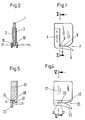
- the device contains a plate-shaped central part 1 and two hook-shaped parts 2 and 3.
- the hook-shaped parts 2 and 3 have a fastening section 4 and a catching section 5, which is bent with respect to the fastening section 4 and provided with a recess 6 is.
- the hook-shaped parts 2, 3 are each fastened on one side of the plate-shaped central part 1 in such a way that the catch sections 5 point in the same direction and form an inlet gap 7 with the plate-shaped central part 1 and that a section 8 of the plate-shaped central part 1 and a section 9 of the hook-shaped part 2, 3 overlap each other. Since the catching sections 5 are laterally offset with respect to the fastening section 4, there is in each case a gap 10 between the sections 8, 9, which form a zigzag receptacle.
- parts 1 to 3 consist of sheet metal. It is obvious to the person skilled in the art that other materials, for example plastic, ceramic or the like, can also be used.
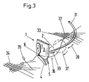
- the device described above is part of a strip laying device, which also includes a strip laying needle 31, in order to produce an insertion edge.
- the last laying device is arranged in such a way that it is located in the area of the stop edge 32 and between the fabric edge 33 and the auxiliary edge 34.
- the selvage needle 31 is arranged in the weaving machine in a manner known per se and is therefore not described in detail.
- the device is connected to a holder, not shown, which is movably arranged such that the device assumes a certain position when the weft thread is struck, as will be explained below.
- the weft thread is passed through the shed 35 past the device into the compartment of the auxiliary edge, the weft thread still being held on both sides. With the subsequent stop movement of the reed, the weft thread is pushed into the device 1 until the weft thread lies in the recesses 6. These recesses 6 form a retraction lock and prevent the weft thread from being pulled out of a position it has taken up in the warp-running direction when the reed is swung back after striking. After the weft, the weft thread is fixed in the fabric and in the auxiliary edge by crossing the warp thread. The weft thread is cut by means of a cutting device 35 on the side of the auxiliary edge 34.
- the weft end 36 produced in this way is then held on the one hand in the fabric 33 and on the other hand in the device.
- This holding of the weft end 35 is brought about by the triple deflection within the zigzag receptacle.
- the holding force results from the frictional force caused by the partial wrapping of parts 1 to 3 (Fig. 2).
- the friction force that occurs can be predetermined by the extent of the wrapping.
- the weft thread end 36 is placed around the provided groin needle 31 by means of the device.
- the movably arranged device performs, for example, a circular movement whose track 37 lies in a plane running approximately perpendicular to the track 38 of the groin needle 31.
- the weft thread end 35 is gripped by the hook 39 of the groin needle 31. While the device is performing this movement, the weft end is held so that the weft end does not become loose.
- the weft end is then inserted into the open shed in a manner known per se.
- the selvage needle pulls the weft end overcoming the holding force in the direction of its longitudinal extension from the zigzag receptacle, so that the weft end is taken over under a predetermined condition. This condition ensures a uniform insertion of the weft ends and consequently a uniform insertion edge on the fabric edge.
- FIGS. 4 and 5 show a device which is made in one piece, e.g. is designed as a pressed or cast part.
- the device has a substantially cuboid body 21, on which a flat section 22 and a hook-shaped section 23 are formed with a recess 24, which form an inlet gap 25 and overlap in sections 26, 27. Since section 22 and hook-shaped section 23 are spaced apart, there is a gap 28 between sections 22 and 23, which forms a zigzag receptacle.
- the device described above performs the same function as described in connection with FIG. 3.
- the device contains a body 1 to 3, which forms a gap with a retraction lock 8, in which a weft thread end inserted and fixed in a direction transverse to its longitudinal extension is held in a zigzag shape.
- the device is arranged in such a way that the gap with the retraction lock 8 extends in the warp direction in order to receive a weft end and interacts with a selvage needle 31, which weft end 36 against the holding force caused by a frictional resistance in the Pulls out the weft direction and places it in the open shed.
- the weft thread end 36 is held by the reed by the zigzag receptacle after the weft thread has struck and is transferred to the last laying needle under constant conditions in order to produce a uniform insertion edge.
Abstract
Description
Die Erfindung betrifft eine Vorrichtung zum Halten des Schussfadenendes bei einer Webmaschine gemäss dem Oberbegriff des Anspruches 1 und eine Webmaschine mit einer solchen Vorrichtung.The invention relates to a device for holding the weft end in a weaving machine according to the preamble of
Es ist eine sogenannte Randklemme (CH-PS 255 691) bekannt, die den Schussfaden in der Eintragbahn fassen und festhalten, bis der Schussfaden an den Warenrand angeschlagen ist. Um zu verhindern, dass das Schussfadenende während des Webblattanschlages herausgerissen wird, muss die Klemmkraft gesteuert werden.A so-called edge clamp (CH-PS 255 691) is known which grips and holds the weft thread in the entry path until the weft thread has struck the edge of the goods. In order to prevent the weft end from being torn out during the reed stop, the clamping force must be controlled.
Als nachteilig erweist sich das Klemmen bei sehr langfaserigen Garnen, insbesondere wenn diese Oberflächen behandelt sind, was zu Verschmutzung der Randklemme führt. Durch die Steuerung der Klemmkraft ist der apparative Aufwand sehr gross und die Randklemme ist bei hohen Maschinendrehzahlen störanfällig. Durch die notwendigerweise hohe Klemmkraft werden schliesslich im Gewebe Quetschmarken sichtbar, wodurch die Gewebequalität gemindert ist.Clamping proves to be disadvantageous in the case of very long-fiber yarns, in particular if these surfaces have been treated, which leads to contamination of the edge clamp. By controlling the clamping force, the outlay on equipment is very great and the edge clamp is prone to failure at high machine speeds. Due to the necessarily high clamping force, pinch marks are finally visible in the tissue, which reduces the quality of the tissue.
Neben der genannten Randklemme ist eine Einrichtung bekannt geworden, bei der beidseits einer Schneidvorrichtung ein Halteelement angeordnet ist. Der einerseits im Gewebe und an der Hilfskante gehaltene Schussfaden wird in den Halteelementen bezüglich der Schneidvorrichtung positioniert. Bei dieser Einrichtung liegt nach dem Schneiden das Schussfadenende frei in einem Halteelement und löst sich vom Halteelement bevor dieses von der Leistenlegernadel erfasst wird, wobei je nach Umfang der Loslösung die Leistenlegernadel das Schussfadenende unterschiedlich erfasst und somit unterschiedliche lange Fadenabschnitte einlegt, was als Nachteil anzusehen ist.In addition to the edge clamp mentioned, a device has become known in which one on both sides Cutting device a holding element is arranged. The weft thread held on the one hand in the fabric and on the auxiliary edge is positioned in the holding elements with respect to the cutting device. In this device, after the cutting, the weft end lies freely in a holding element and detaches from the holding element before it is grasped by the last layer needle, depending on the extent of the detachment, the last layer needle detects the weft end differently and thus inserts different long thread sections, which is to be regarded as a disadvantage .
Der Erfindung liegt die Aufgabe zugrunde, eine Vorrichtung zum Halten eines am Geweberand vorstehenden Schussfadenendes zu schaffen, die unter Vermeidung jeglicher Klemmwirkung eine einwandfreie Uebergabe des Schussfadens unter gleichbleibenden Bedingungen gewährleistet.The invention has for its object to provide a device for holding a weft thread protruding from the fabric edge, which ensures a perfect transfer of the weft thread under constant conditions while avoiding any clamping action.
Diese Aufgabe wird erfindungsgemäss durch die kennzeichnenden Merkmale des Anspruches 1 gelöst.According to the invention, this object is achieved by the characterizing features of
Die mit der Vorrichtung erzielbaren Vorteile sind im wesentlichen darin zu sehen, dass eine Verschmutzung bzw. Beschädigung der Vorrichtung bzw. des Schussfadenendes vermieden wird und dass eine einwandfreie Uebernahme des Schussfadenendes gewährleistet ist.The advantages which can be achieved with the device are essentially to be seen in the fact that contamination or damage to the device or the weft thread end is avoided and that the weft thread end is properly taken over.
Nachfolgend wird die Erfindung anhand der beiliegenden Zeichnungen erläutert.The invention is explained below with reference to the accompanying drawings.
Es zeigen:
- Fig. 1
- eine Seitenansicht einer Ausführungsform einer erfindungsgemässen Vorrichtung;
- Fig. 2
- einen Schnitt entlang der Linie II-II in Fig. 1;
- Fig. 3
- die Vorrichtung nach Fig. 1 und eine damit zusammenwirkende Leistenlegernadel in räumlicher Darstellung;
- Fig. 4
- eine Seitenansicht einer anderen Ausführungsform einer erfindungsgemässen Vorrichtung;
- Fig. 5
- einen Schnitt entlang der Linie V-V in Fig. 4.
- Fig. 1
- a side view of an embodiment of a device according to the invention;
- Fig. 2
- a section along the line II-II in Fig. 1;
- Fig. 3
- the device of Figure 1 and a cooperating groin needle in a spatial representation.
- Fig. 4
- a side view of another embodiment of a device according to the invention;
- Fig. 5
- a section along the line VV in Fig. 4th
Wie die Fig. 1 und 2 zeigen enthält die Vorrichtung einen plattenförmigen Mittelteil 1 und zwei hakenförmige Teile 2 und 3. Die hakenförmigen Teile 2 und 3 haben einen Befestigungsabschnitt 4 und einen Fangabschnitt 5, der bezüglich dem Befestigungsabschnitt 4 abgekröpft und mit einer Ausnehmung 6 versehen ist.As shown in FIGS. 1 and 2, the device contains a plate-shaped
Die hakenförmigen Teile 2, 3 sind jeweils an einer Seite des plattenförmigen Mittelteiles 1 so befestigt, dass die Fangabschnitte 5 in die gleiche Richtung weisen und mit dem plattenförmigen Mittelteil 1 einen Einlaufspalt 7 bilden und dass sich ein Abschnitt 8 des plattenförmigen Mittelteiles 1 und ein Abschnitt 9 des hakenförmigen Teiles 2, 3 einander überlappen. Da die Fangabschnitte 5 bezüglich dem Befestigungsabschnitt 4 seitlich versetzt ausgebildet sind, besteht zwischen den Abschnitten 8, 9 jeweils ein Spalt 10, die eine Zickzackaufnahme bilden.The hook-
Bei der vorstehend beschriebenen Vorrichtung bestehen die Teile 1 bis 3 aus Metallblech. Es ist für den Fachmann offensichtlich, dass auch andere Materialien z.B. Kunststoff, Keramik oder dgl. verwendet werden können.In the device described above,
Eine weitere Möglichkeit besteht darin die Teile 1 bis 3 aus Draht herzustellen, um die Vorrichtung massearm auszubilden. Als vorteilhaft erweist sich, wenn der Draht aus Federstahl besteht.Another possibility is to produce
Wie die Fig. 3 zeigt, ist die vorstehend beschriebene Vorrichtung ein Teil einer Leistenlegervorrichtung zu der auch eine Leistenlegernadel 31 gehört, um eine Einlegekante zu erzeugen.As shown in FIG. 3, the device described above is part of a strip laying device, which also includes a
In einer Webmaschine ist die Leistenlegervorrichtung so angeordnet, dass sie sich im Bereich der Anschlagkante 32 und zwischen dem Geweberand 33 und der Hilfskante 34 befindet. Die Leistenlegernadel 31 ist in an sich bekannter Weise in der Webmaschine angeordnet und wird daher nicht näher beschrieben.In a weaving machine, the last laying device is arranged in such a way that it is located in the area of the
Die Vorrichtung ist mit einem nicht dargestellten Halter verbunden, der beweglich so angeordnet ist, dass die Vorrichtung beim Anschlagen des Schussfadens eine bestimmte Stellung einnimmt, wie nachfolgend erläutert wird.The device is connected to a holder, not shown, which is movably arranged such that the device assumes a certain position when the weft thread is struck, as will be explained below.
Die nachfolgende Beschreibung beginnt mit dem Eintragen des Schussfadens. Zu diesem Zeitpunkt befindet sich die Leistenlegernadel 31 in der zurückgezogenen Stellung und die Vorrichtung ist so positioniert, dass die Ausnehmungen 6 in den hakenförmigen Teilen 2, 3 (Fig. 1) mit der Anschlagkante 32 fluchten.The following description begins with the insertion of the weft thread. At this time, the
Beim Eintragen wird der Schussfaden durch das Webfach 35 an der Vorrichtung vorbei in das Fach der Hilfskante geführt, wobei der Schussfaden beidseits noch gehalten wird. Mit der nachfolgenden Anschlagbewegung des Webblattes wird der Schussfaden in die Vorrichtung 1 hineingeschoben, bis der Schussfaden in den Ausnehmungen 6 liegt. Diese Ausnehmungen 6 bilden eine Rückziehsperre und verhindern, dass der Schussfaden beim Zurückschwenken des Webblattes nach dem Anschlagen aus einer dann eingenommenen Lage in der Kettlaufrichtung herausgezogen wird. Nach dem Anschlagen ist der Schussfaden im Gewebe und in der Hilfskante durch Verkreuzen der Kettfaden festgelegt. Der Schussfaden wird mittels einer Schneidvorrichtung 35 auf der Seite der Hilfskante 34 geschnitten. Das dabei erzeugte Schussfadenende 36 ist dann einerseits im Gewebe 33 und andererseits in der Vorrichtung gehalten. Dieses Halten des Schussfadenendes 35 wird durch die dreifache Umlenkung innerhalb der Zickzackaufnahme bewirkt. Die Haltekraft ergibt sich dabei durch die Reibungskraft, die durch die teilweise Umschlingung der Teile 1 bis 3 (Fig. 2) entsteht. Die auftretende Reibungskraft kann durch den Umfang der Umschlingung vorbestimmt werden. In der Folge wird das Schussfadenende 36 mittels der Vorrichtung um die bereitgestellte Leistenlegernadel 31 gelegt. Hierzu führt die beweglich angeordnete Vorrichtung eine z.B. kreisförmige Bewegung deren Laufbahn 37 in einer etwa senkrecht zur Laufbahn 38 der Leistenlegernadel 31 verlaufenden Ebene liegt. Dadurch wird das Schussfadenende 35 durch den Haken 39 der Leistenlegernadel 31 erfasst. Während die Vorrichtung diese Bewegung ausführt, wird das Schussfadenende gehalten, so dass das Schussfadenende nicht locker wird.During insertion, the weft thread is passed through the
Nachfolgend wird das Schussfadenende in an sich bekannter Weise in das offene Webfach eingelegt. Hierbei zieht die Leistenlegernadel das Schussfadenende unter Ueberwindung der Haltekraft in Richtung seiner Längserstreckung aus der Zickzackaufnahme, so dass die Uebernahme des Schussfadenendes unter einer vorbestimmten Bedingung erfolgt. Diese Bedingung gewährleistet ein gleichmässiges Einlegen der Schussfadenenden und in der Folge eine gleichmässige Einlegekante am Geweberand.The weft end is then inserted into the open shed in a manner known per se. Here, the selvage needle pulls the weft end overcoming the holding force in the direction of its longitudinal extension from the zigzag receptacle, so that the weft end is taken over under a predetermined condition. This condition ensures a uniform insertion of the weft ends and consequently a uniform insertion edge on the fabric edge.
Die Fig. 4 und 5 zeigen eine Vorrichtung die einstückig, z.B. als Press- bzw. Gussteil ausgebildet ist. Die Vorrichtung hat einen im wesentlichen quaderförmigen Körper 21, an dem ein ebener Abschnitt 22 und ein hakenförmiger Abschnitt 23 mit einer Ausnehmung 24 ausgebildet sind, die einen Einlaufspalt 25 bilden und sich abschnittweise 26, 27 überlappen. Da der Abschnitt 22 und der hakenförmige Abschnitt 23 zueinander beabstandet sind, besteht zwischen den Abschnitten 22 und 23 ein Spalt 28, der eine Zickzackaufnahme bildet.4 and 5 show a device which is made in one piece, e.g. is designed as a pressed or cast part. The device has a substantially
Als Teil einer Leistenlegervorrichtung erfüllt die vorstehend beschriebene Vorrichtung die gleiche Funktion, wie in Zusammenhang mit Fig. 3 beschrieben ist.As part of a strip laying device, the device described above performs the same function as described in connection with FIG. 3.
Die Anwendung der vorstehend beschriebenen Vorrichtung wurde vorgängig in Verbindung mit einer auf der Schuss und/oder Fangseite üblicherweise verwendeten Hilfskante erläutert. Diese Vorrichtung kann ebenfalls zwischen Gewebebahnen zusammen mit einer sogenannten Trennleistenlegereinrichtung unter Verzicht auf eine Hilfskante verwendet werden. Das gleiche gilt für Webmaschinen, bei denen schusseitig der jeweilige Schussfaden nach dem Anschlagen durch das Webblatt von der Schussschere geschnitten und das Schussfadenende für einen nachfolgenden Schusseintrag in einer Klemme gehalten wird.The application of the device described above was previously explained in connection with an auxiliary edge usually used on the weft and / or catch side. This device can also be used between fabric sheets together with a so-called separating strip laying device, without an auxiliary edge. The same applies to weaving machines in which the respective weft thread is cut by the weft scissors on the weft side after being struck by the reed and the weft thread end is held in a clamp for subsequent weft insertion.
Die Vorrichtung enthält einen Körper 1 bis 3, der einen Spalt mit einer Rückziehsperre 8 bildet, in welchen ein in einer Richtung quer zu seiner Längserstreckung eingeführtes und festgelegtes Schussfadenende zickzackförmig gehalten ist. Die Vorrichtung ist so angeordnet, dass sich der Spalt mit der Rückziehsperre 8 in Kettrichtung erstreckt, um ein Schussende aufzunehmen und mit einer Leistenlegernadel 31 zusammenwirkt, welche das Schussfadenende 36 gegen die durch einen Reibungswiderstand bewirkte Haltekraft in der Schussrichtung herauszieht und in das offene Webfach einlegt.The device contains a
Das Schussfadenende 36 wird nach dem Anschlag des Schussfadens durch das Webblatt durch die Zickzackaufnahme gehalten und unter gleichbleibenden Bedingungen an die Leistenlegernadel übergeben, um eine gleichmässige Einlegekante zu erzeugen.The
Claims (9)
Priority Applications (1)
| Application Number | Priority Date | Filing Date | Title |
|---|---|---|---|
| EP93810535A EP0636723A1 (en) | 1993-07-26 | 1993-07-26 | Device for holding the weft end and loom with such device |
Applications Claiming Priority (1)
| Application Number | Priority Date | Filing Date | Title |
|---|---|---|---|
| EP93810535A EP0636723A1 (en) | 1993-07-26 | 1993-07-26 | Device for holding the weft end and loom with such device |
Publications (1)
| Publication Number | Publication Date |
|---|---|
| EP0636723A1 true EP0636723A1 (en) | 1995-02-01 |
Family
ID=8215006
Family Applications (1)
| Application Number | Title | Priority Date | Filing Date |
|---|---|---|---|
| EP93810535A Withdrawn EP0636723A1 (en) | 1993-07-26 | 1993-07-26 | Device for holding the weft end and loom with such device |
Country Status (1)
| Country | Link |
|---|---|
| EP (1) | EP0636723A1 (en) |
Cited By (1)
| Publication number | Priority date | Publication date | Assignee | Title |
|---|---|---|---|---|
| US6107392A (en) * | 1994-01-21 | 2000-08-22 | E. I. Du Pont De Nemours And Company | Aqueous branched polymer dispersion |
Citations (3)
| Publication number | Priority date | Publication date | Assignee | Title |
|---|---|---|---|---|
| CH255691A (en) * | 1946-06-07 | 1948-07-15 | Sulzer Ag | Method and device for the production of fabrics on rapier looms. |
| NL7704471A (en) * | 1977-04-22 | 1978-10-24 | Rueti Te Strake Bv | Weft thread clamp for selvedge in shuttleless loom - prevents loosening of threads and assists temples to maintain width |
| US5158119A (en) * | 1990-08-29 | 1992-10-27 | Vamatex S.P.A. | Selvedge forming device for shuttleless looms with linear motor control system |
-
1993
- 1993-07-26 EP EP93810535A patent/EP0636723A1/en not_active Withdrawn
Patent Citations (3)
| Publication number | Priority date | Publication date | Assignee | Title |
|---|---|---|---|---|
| CH255691A (en) * | 1946-06-07 | 1948-07-15 | Sulzer Ag | Method and device for the production of fabrics on rapier looms. |
| NL7704471A (en) * | 1977-04-22 | 1978-10-24 | Rueti Te Strake Bv | Weft thread clamp for selvedge in shuttleless loom - prevents loosening of threads and assists temples to maintain width |
| US5158119A (en) * | 1990-08-29 | 1992-10-27 | Vamatex S.P.A. | Selvedge forming device for shuttleless looms with linear motor control system |
Cited By (1)
| Publication number | Priority date | Publication date | Assignee | Title |
|---|---|---|---|---|
| US6107392A (en) * | 1994-01-21 | 2000-08-22 | E. I. Du Pont De Nemours And Company | Aqueous branched polymer dispersion |
Similar Documents
| Publication | Publication Date | Title |
|---|---|---|
| DE2845299C2 (en) | Shuttleless rapier weaving machine | |
| CH477579A (en) | Floor covering material made from pile fabric | |
| DE3033201C2 (en) | ||
| EP0146663B1 (en) | Weft inserting device for a needle loom | |
| EP0644286A1 (en) | Arrangement to feed weft yarns | |
| DE2637618B2 (en) | Tape fabric | |
| DE3200638A1 (en) | PROTECTIVE WEAVING MACHINE | |
| DE3240569C1 (en) | Device on a contactless weaving machine for forming a fabric edge | |
| DE2121430A1 (en) | Weaving method and device for forming a fabric edge with protrude the weft thread | |
| EP0351361A1 (en) | Pneumatic selvedge-forming unit for looms | |
| DE3812960A1 (en) | GRIPPER WEAVING MACHINE | |
| DE202019101093U1 (en) | Device for cutting the weft threads in a rapier loom without forming a false selvage | |
| EP0624671B1 (en) | Thread retainer for a supply gripper and gripper loom with thread retainer | |
| DE1535414B1 (en) | Method for forming thinned insert edges when producing fabrics on weaving machines with removal of the weft thread from stationary supply bobbins and device for carrying out the method | |
| EP0636723A1 (en) | Device for holding the weft end and loom with such device | |
| DE19548846C1 (en) | Inserting pick end into loom shed | |
| DE2639203C3 (en) | Method for producing an insert strip on a fabric and device for carrying out the method | |
| DE2041432B2 (en) | Yarn clamp for weft yarn insertion members on weaving machines | |
| DE3002345C2 (en) | Needle for tufting machines | |
| WO1999018274A1 (en) | Conveyor gripper for a gripper weaving machine | |
| DE2625746C2 (en) | Thread clamp, in particular for weaving machines | |
| EP0776390B1 (en) | Gripper weaving machine | |
| DE2925694C2 (en) | Weft insertion element of a shuttleless loom | |
| EP0508947A1 (en) | Carrier gripper for gripper looms | |
| AT264404B (en) | Weft thread insertion link for a loom |
Legal Events
| Date | Code | Title | Description |
|---|---|---|---|
| PUAI | Public reference made under article 153(3) epc to a published international application that has entered the european phase |
Free format text: ORIGINAL CODE: 0009012 |
|
| AK | Designated contracting states |
Kind code of ref document: A1 Designated state(s): BE DE IT |
|
| RBV | Designated contracting states (corrected) |
Designated state(s): BE DE IT |
|
| 17P | Request for examination filed |
Effective date: 19950705 |
|
| STAA | Information on the status of an ep patent application or granted ep patent |
Free format text: STATUS: THE APPLICATION HAS BEEN WITHDRAWN |
|
| 18W | Application withdrawn |
Withdrawal date: 19950830 |