EP0636313B1 - Vorrichtung zum automatischen Melken von Tieren - Google Patents
Vorrichtung zum automatischen Melken von Tieren Download PDFInfo
- Publication number
- EP0636313B1 EP0636313B1 EP94202169A EP94202169A EP0636313B1 EP 0636313 B1 EP0636313 B1 EP 0636313B1 EP 94202169 A EP94202169 A EP 94202169A EP 94202169 A EP94202169 A EP 94202169A EP 0636313 B1 EP0636313 B1 EP 0636313B1
- Authority
- EP
- European Patent Office
- Prior art keywords
- resting
- construction
- box
- animal
- boxes
- Prior art date
- Legal status (The legal status is an assumption and is not a legal conclusion. Google has not performed a legal analysis and makes no representation as to the accuracy of the status listed.)
- Expired - Lifetime
Links
Images

Classifications
-
- A—HUMAN NECESSITIES
- A01—AGRICULTURE; FORESTRY; ANIMAL HUSBANDRY; HUNTING; TRAPPING; FISHING
- A01K—ANIMAL HUSBANDRY; AVICULTURE; APICULTURE; PISCICULTURE; FISHING; REARING OR BREEDING ANIMALS, NOT OTHERWISE PROVIDED FOR; NEW BREEDS OF ANIMALS
- A01K11/00—Marking of animals
- A01K11/006—Automatic identification systems for animals, e.g. electronic devices, transponders for animals
-
- A—HUMAN NECESSITIES
- A01—AGRICULTURE; FORESTRY; ANIMAL HUSBANDRY; HUNTING; TRAPPING; FISHING
- A01J—MANUFACTURE OF DAIRY PRODUCTS
- A01J5/00—Milking machines or devices
- A01J5/017—Automatic attaching or detaching of clusters
- A01J5/0175—Attaching of clusters
-
- A—HUMAN NECESSITIES
- A01—AGRICULTURE; FORESTRY; ANIMAL HUSBANDRY; HUNTING; TRAPPING; FISHING
- A01K—ANIMAL HUSBANDRY; AVICULTURE; APICULTURE; PISCICULTURE; FISHING; REARING OR BREEDING ANIMALS, NOT OTHERWISE PROVIDED FOR; NEW BREEDS OF ANIMALS
- A01K1/00—Housing animals; Equipment therefor
- A01K1/12—Milking stations
-
- A—HUMAN NECESSITIES
- A01—AGRICULTURE; FORESTRY; ANIMAL HUSBANDRY; HUNTING; TRAPPING; FISHING
- A01K—ANIMAL HUSBANDRY; AVICULTURE; APICULTURE; PISCICULTURE; FISHING; REARING OR BREEDING ANIMALS, NOT OTHERWISE PROVIDED FOR; NEW BREEDS OF ANIMALS
- A01K15/00—Devices for taming animals, e.g. nose-rings or hobbles; Devices for overturning animals in general; Training or exercising equipment; Covering boxes
- A01K15/02—Training or exercising equipment, e.g. mazes or labyrinths for animals ; Electric shock devices; Toys specially adapted for animals
- A01K15/029—Electric or similar shock devices for livestock, e.g. prods
Definitions
- the present invention relates to a construction or a similar arrangement for automatically milking animals, such as cows, comprising a milking box and a plurality of resting boxes, the construction furthermore comprising compelling means.
- a resting box includes the means for compelling the animal resting in the resting box to leave same and the resting box includes a cow identification sensor which, together with a transponder to be carried by the animal, forms part of a cow identification system, the resting box furthermore includes a warning member for warning animals not to enter the resting box, or to warn an animal present in the resting box to leave same.
- the construction according to the invention makes it more certain that a selected animal will be milked at a predetermined instant, preferably e.g. eight hours, after the preceding milking.
- a warning member By means of the warning member an animal can be prevented from entering a resting box, e.g. because an animal has already left an other resting box with the purpose of going to the milking box, or because too little time has elapsed since the previous milking run, so that the teats of the animal milked have closed or dried insufficiently.
- the warning member may be constituted by a computer-controlled flashing light which, preferably, is screened off in such a manner that it is not visible in other resting boxes.
- a resting box For the purpose of obviating symptoms of a disease, more specifically those relating to the udder, to the best possible extent, it is advantageous, in accordance with the invention, for a resting box to be equipped with a disinfecting unit for disinfecting the area where an animal has been lying, after it has left the resting box.
- a line may run along the resting boxes for the supply of a disinfectant, whilst sprayers having a computer-controlled valve can be connected thereto.
- a power supply cable will be run along the resting boxes as well as a process control cable for the individual resting boxes.
- process control cables it will be possible to control from a remote computer system a warning member and/or expelling member and/or disinfecting unit present in a resting box.
- the resting boxes are preferably arranged along the outer wall of the construction.
- both the outer wall of the construction near the resting boxes and the floor of the resting boxes must be provided with a thermal insulation.
- arranged along the outer walls of the construction there may be feeding stations which are placed nearer to the centre of the construction, so that there is a walking area between the resting boxes and the feeding stations and the animals can walk in a given direction through the shed.
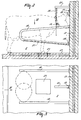
- the construction for automatically milking animals shown in Figure 1 is here formed by a shed 1, in which resting boxes 2 are arranged at the two longitudinal sides thereof against the outer wall.
- Feeding stations 4 and 5 are arranged on both sides of a feeding passage 3.
- fodder can be carried via the door 6 in the shed 1 to the feeding troughs 7 of the feeding stations 4.
- feeding stations 5 in which concentrate is fed to the animals.
- the arrangement of the resting boxes 2 and the feeding stations 4 and 5 is such that sufficient room for the animals to walk between the resting boxes and the feeding stations remain, so that they can move about to a sufficient extent and can basically walk around the shed.
- a selection box 8 At the short side of the shed, opposite the short side in which the door 6 is present, there are a number of special boxes, namely a selection box 8, a cleaning box 9 and a milking box 10. These three boxes are arranged such that animals can pass through the three boxes in the said sequence in the longitudinal direction. Next to these three boxes there is a computer room 11, from which the actions to be performed in the selection box 8, the cleaning box 9, the milking box 10, the feeding stations 5 and the resting boxes 2 are controlled.
- the walking area 12 is formed by the space between the resting boxes 2 and the feeding stations 4 and 5, and the space between the feeding stations 4 and the short side of the shed 1 where the door 6 is located, whilst the possibility for the animals to walk about in the construction is created by the fact that the selection box 8, the cleaning box 9 and the milking box 10 are incorporated in the walking area 12. Of the animals reporting at the selection box 8 it must be determined whether they are to be milked or not. In the negative case, the animals are guided back from the selection box 8 to the walking area 12. If an animal is indeed to be milked, then it is allowed to proceed to the cleaning box 9, where the teats of the animal are cleaned, whereafter the animal is passed on to the milking box 10.
- the milking box 10 there is a milking robot for the automatic connection of teat cups to the teats of an animal to be milked and for the subsequent automatic milking of the animal. Should it be found during this milking operation that the milk yield is insufficient, or that the milk is affected by e.g. mastitis, then the relevant ill or unproductive animal can be separated from the herd by leading it from the milking box 10 to a special reception area 13, instead of allowing the milked animal access again to the walking area 12.
- all the resting boxes 2, all the feeding stations 4 and 5, and also the selection box 8 are provided with a cow identification sensor 14 which, together with a transponder 15 to be carried by the animals, forms part of a cow identification system.
- the cow identification sensors 14 are linked to a computer system in the computer room 11. Thus, using the cow identification system, it can be recorded in the computer which animal is present at any moment in which resting box 2 or in which feeding station 5 and also how long the animals have already rested more particularly in the resting boxes 2.
- the feeding stations 4 are separated from each other by vertical posts 16.
- the feeding stations 5, in which concentrate can be supplied to the animals, are formed by boxes which are separated from each other.
- Each of the feeding stations 5 is linked to the computer system in the computer room 11, so that it can be recorded for each animal how much concentrate it has consumed, which is important for judging the health condition of the animals.
- the resting boxes are separated from each other by cubicle partitions 18. All the resting boxes 2, and preferably also all the feeding stations 5, are equipped with a warning member 19 constituted by a flash light.
- the flash lights are screened off in such a manner that they are not visible in other resting boxes. By means of these flash lights, which can be controlled individually for each box from the computer room 11, the animals can be warned not to enter the relevant resting box 2 or to leave same.
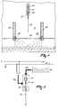
- This expelling member 20 operates on the basis of electric shocks, and is formed by a spring-loaded electric fence wire which is suspended from a support 21 attached to the shed wall and contacts the head or neck of the animal in a resting box 2. Besides being arranged above the resting boxes 2, such an expelling member 20 can also be applied above the troughs of the concentrate feeding stations 5 and the feeding stations 4. In Figure 1 these electric fence wires of the expelling members 20 are designated by dots 22. The electric fence wire is attached to the support 21 via a conically wound spring.
- Figure 1 shows the electric fence wire 22 in only a limited number of resting boxes and feeding stations. This wire can of course also be used in other resting boxes and feeding stations.
- the expelling member 20 operating on the basis of electric fence wire is controlled by the computer system in the computer room 11. The expelling member is then not only controlled in such a manner that at the instant determined by the computer system electric shocks are applied to the animals in the relevant resting boxes or feeding stations, but it is also possible to increase the intensity of the electric shocks gradually and automatically.
- a ground plate 23 is accommodated in the floor of the relevant boxes and feeding stations.
- the supply voltages and control signals required for operating the cow identification sensor 14, the warning member 19 and the expelling member 20 are fed to the relevant resting boxes and feeding stations via a supply voltage wiring system 24 and process control wiring system 25, both shown schematically in Figure 5.
- the resting boxes 2 additionally include a disinfecting implement for disinfecting, after an animal has left the relevant resting box, this resting box.
- a line 26 for the supply of a disinfectant runs along the resting boxes.
- a line 27, which is connected to this line 26 and runs through or along the cubicle partitions 18 and at its end is provided with a spray nozzle, a disinfecting liquid can be sprayed onto the lying area of the animal in the resting box, as soon as this animal has left same, whilst more specifically is disinfected the place in which the udder contacts the floor.
- a line 27 having a spray nozzle at its end in or along the two cubicle partitions 18, a portion of the resting area can be sprayed from both sides.
- That portion of the resting area which is covered by two of these spray nozzles is denoted in Figure 3 by means of broken lines.
- a valve 28 which is controlled by the computer system in the computer room 11, so that a given valve or given valves can be opened at the instant at which it is determined by the computer that an animal has left the resting box.
- the shed described here is designed as a loose housing for approximately eighty animals, forty resting boxes having been arranged on either side of the shed and twice forty feeding stations having been arranged in the centre of the shed.
- a check is to be made whether it is eligible for milking. If an insufficient period of time after the previous milking turn has elapsed, the animal can be denied access to the milking box 10.
- partitioning means between the selection box 8 and the walking area 12 on the one hand, and between the selection box 8 and the cleaning box 9 on the other, it is possible by means of the cow identification data to establish whether an animal having entered the selection box must be send back to the walking area 12 or may be allowed to proceed to the cleaning box.
- the computer system can control partitioning means between on the one hand the milking box 10 and the collecting area 13 and on the other hand between the milking box 10 and the walking area 12 in that sense that the animal milked is led to either the collecting area 13 or the walking area 12.
- the resting boxes are provided with the warning member 19, formed by a flash light, and an expelling member 20 which gives electric shocks to the animal. After the animals have proceeded to the feeding station and have eaten, they may thereafter go to a resting box.
- the flash light warns them to leave the resting box. If they do not do so, they are given increasingly intensive electric shocks via the electric fence wire, until they leave the resting box. Since, using the cow identification system present in all the boxes, it can at all times be determined which animal is present at which instant in which box, an animal can always be driven at the proper instant from a given box to go to the milking box 10.
- the animal can be milked for 5 to 10 minutes with the aid of the computer system, whilst, with the aid of the computer system, an animal is encouraged to take food, to ruminate and to rest after milking for approximately 500 minutes, whereafter the computer system provides that this cycle is automatically repeated.
Landscapes
- Life Sciences & Earth Sciences (AREA)
- Environmental Sciences (AREA)
- Animal Husbandry (AREA)
- Zoology (AREA)
- Biodiversity & Conservation Biology (AREA)
- Health & Medical Sciences (AREA)
- General Health & Medical Sciences (AREA)
- Physical Education & Sports Medicine (AREA)
- Animal Behavior & Ethology (AREA)
- Birds (AREA)
- Housing For Livestock And Birds (AREA)
- Catching Or Destruction (AREA)
Claims (19)
- Vorrichtung oder ähnliche Anordnung zum automatischen Melken von Tieren, wie z. B. Kühen, mit einer Melkbox (10) und mehreren Ruheboxen (2), wobei die Vorrichtung ferner eine Austreibevorrichtung aufweist,
dadurch gekennzeichnet, daß eine Ruhebox (2) die Austreibevorrichtung (20) enthält, mittels der das in der Ruhebox (2) ruhende Tier gezwungen wird, diese zu verlassen, und daß die Ruhebox (2) einen Kuhidentifizierungssensor (14) aufweist, der zusammen mit einem von dem Tier zu tragenden Transponder (15) Teil eines Kuhidentifizierungssystems ist, wobei die Ruhebox (2) ferner eine Warneinrichtung (19) aufweist, um Tiere zurückzuhalten, die Ruhebox (2) zu betreten, oder um ein in der Ruhebox (2) befindliches Tier anzuhalten, die Box zu verlassen. - Vorrichtung nach Anspruch 1,
dadurch gekennzeichnet, daß die Warneinrichtung (19) durch ein rechnergesteuertes Blitzlicht gebildet ist. - Vorrichtung nach Anspruch 2,
dadurch gekennzeichnet, daß das Blitzlicht (19) derart abgeschirmt ist, daß es in anderen Ruheboxen (2) nicht sichtbar ist. - Vorrichtung nach Anspruch 2 oder 3,
dadurch gekennzeichnet, daß das Blitzlicht (19) aktiviert wird, wenn das in der Ruhebox (2) befindliche Tier zu melken ist. - Vorrichtung nach einem der vorhergehenden Ansprüche,
dadurch gekennzeichnet, daß eine Austreibevorrichtung (20) betätigt wird, die dem Tier Elektroschocks versetzt, wenn das Tier nach einer vorgegebenen Anzahl von Sekunden nach Aktivieren der Warneinrichtung (19) die Ruhebox (2) nicht verlassen hat. - Vorrichtung nach Anspruch 5,
dadurch gekennzeichnet, daß die Stärke der Elektroschocks automatisch zu steigern ist. - Vorrichtung nach Anspruch 5,
dadurch gekennzeichnet, daß die Elektroschocks erzeugende Austreibevorrichtung (20) durch einen freihängenden Elektrozaundraht (22) gebildet ist, der über eine konische Feder an einem Halter über der betreffenden Ruhebox (2) angebracht ist. - Vorrichtung nach einem der Ansprüche 5 bis 7,
dadurch gekennzeichnet, daß der Boden der Ruhebox (2) eine Erdungsplatte (23) aufweist. - Vorrichtung nach einem der vorhergehenden Ansprüche,
dadurch gekennzeichnet, daß eine Ruhebox (2) eine Desinfektionsvorrichtung (27, 28) aufweist, um den Ruhebereich zu desinfizieren, nachdem das Tier die Ruhebox (2) verlassen hat. - Vorrichtung nach Anspruch 9,
dadurch gekennzeichnet, daß zum Zuführen einer Desinfektionsflüssigkeit an den Ruheboxen (2) eine Leitung (27) entlanggeführt ist, an die Spritzdüsen mit einem rechnergesteuerten Ventil (28) angeschlossen sind. - Vorrichtung nach einem der vorhergehenden Ansprüche,
dadurch gekennzeichnet, daß ein Stromversorgungskabel (24) sowie ein Prozeßsteuerungskabel (25) für die einzelnen Ruheboxen (2) längs der Ruheboxen (2) angeordnet sind. - Vorrichtung nach Anspruch 11,
dadurch gekennzeichnet, daß ein Computersystem vorhanden ist, das über die Prozeßsteuerungskabel (25) eine in einer Ruhebox (2) angeordnete Warneinrichtung (19) und/oder Austreibevorrichtung (20) und/oder Desinfektionsvorrichtung (27, 28) steuert. - Vorrichtung nach einem der vorhergehenden Ansprüche,
dadurch gekennzeichnet, daß die Ruheboxen (2) an der Außenwand der Vorrichtung angeordnet sind. - Vorrichtung nach Anspruch 13,
dadurch gekennzeichnet, daß der Boden einer Ruhebox (2) und auch die Außenwand der Vorrichtung nahe der Ruhebox (2) eine Wärmeisolierung (17) aufweisen. - Vorrichtung nach Anspruch 13 oder 14,
dadurch gekennzeichnet, daß etwa achtzig Ruheboxen (2) vorhanden sind. - Vorrichtung nach einem der vorhergehenden Ansprüche,
dadurch gekennzeichnet, daß die Vorrichtung eine Anzahl von vorzugsweise achtzig Fütterungsstationen (4, 5) aufweist. - Vorrichtung nach einem der vorhergehenden Ansprüche,
dadurch gekennzeichnet, daß die Vorrichtung einen Bereich aufweist, in dem die Tiere frei umherlaufen können, und von dem aus sie zu den Ruheboxen (2), den Fütterungsstationen (4, 5) und der Melkbox (10) gelangen können. - Vorrichtung nach einem der vorhergehenden Ansprüche,
dadurch gekennzeichnet, daß die Melkbox (10) mindestens einen Melkroboter zum automatischen Anschließen von Zitzenbechern an die Zitzen eines Tieres und zum automatischen Melken eines Tieres aufweist. - Vorrichtung nach einem der vorhergehenden Ansprüche,
dadurch gekennzeichnet, daß die Vorrichtung ein Computersystem aufweist, mittels dessen das Tier 5 bis 10 Minuten lang zu melken ist, und mittels dessen ein Tier dazu zu bringen ist, Nahrung aufzunehmen, wiederzukäuen und etwa 500 Minuten lang zu ruhen oder umherzulaufen, wobei eine computergesteuerte Einrichtung vorhanden ist, um diesen Zyklus automatisch zu wiederholen.
Applications Claiming Priority (2)
| Application Number | Priority Date | Filing Date | Title |
|---|---|---|---|
| NL9301317A NL9301317A (nl) | 1993-07-28 | 1993-07-28 | Inrichting voor het automatisch melken van dieren. |
| NL9301317 | 1993-07-28 |
Publications (3)
| Publication Number | Publication Date |
|---|---|
| EP0636313A2 EP0636313A2 (de) | 1995-02-01 |
| EP0636313A3 EP0636313A3 (de) | 1995-04-05 |
| EP0636313B1 true EP0636313B1 (de) | 1999-03-24 |
Family
ID=19862708
Family Applications (1)
| Application Number | Title | Priority Date | Filing Date |
|---|---|---|---|
| EP94202169A Expired - Lifetime EP0636313B1 (de) | 1993-07-28 | 1994-07-25 | Vorrichtung zum automatischen Melken von Tieren |
Country Status (3)
| Country | Link |
|---|---|
| EP (1) | EP0636313B1 (de) |
| DE (1) | DE69417313T2 (de) |
| NL (1) | NL9301317A (de) |
Families Citing this family (14)
| Publication number | Priority date | Publication date | Assignee | Title |
|---|---|---|---|---|
| IL113675A0 (en) * | 1995-05-09 | 1995-08-31 | Mgh Automation Systems | Hen nesting apparatus and method for utilizing such apparatus for brooding control |
| NL1000474C2 (en) * | 1995-06-01 | 1996-12-03 | Prolion Bv | Automatic animal-milking system |
| NL1000969C2 (nl) * | 1995-08-11 | 1997-02-12 | Maasland Nv | Inrichting voor het lokaliseren van een dier. |
| DE19728415A1 (de) * | 1997-07-03 | 1999-01-07 | Volker Boekhoff | Verfahren und Vorrichtung zur automatisierten landwirtschaftlichen Tierhaltung |
| NL1008334C2 (nl) * | 1998-02-18 | 1999-08-19 | Prolion Bv | Inrichting voor het melken van dieren. |
| SE514627C2 (sv) * | 1998-06-10 | 2001-03-26 | Alfa Laval Agri Ab | Anordning och sätt för att härbärgera mjölkproducerande djur |
| SE0002082D0 (sv) | 2000-06-05 | 2000-06-05 | Delaval Holding Ab | Notification method and system |
| SE517141C2 (sv) | 2000-06-07 | 2002-04-23 | Delaval Holding Ab | Förfarande för mjölkning där djuren rankas samt mjölkningsstall och datorprogramvara härför |
| SE0202112D0 (sv) † | 2002-07-05 | 2002-07-05 | Delaval Holding Ab | Method and device at a dairy farm |
| DE102004016721A1 (de) * | 2004-04-05 | 2005-10-20 | Hartmann Gmbh | Verfahren zum Melken von Kühen in einem dazu mit einer Treib- und Absperrvorrichtung ausgestattetem Stall |
| WO2008051134A1 (en) * | 2006-10-23 | 2008-05-02 | Delaval Holding Ab | Arrangement and method in a milking system |
| NL1035229C2 (nl) * | 2008-03-31 | 2009-10-01 | Lely Patent Nv | Omgeving ingericht voor het houden van dieren. |
| CA2841879C (en) | 2011-07-11 | 2019-05-21 | Delaval Holding Ab | A device to motivate an animal to leave a milking stall |
| AT14067U1 (de) * | 2014-06-16 | 2015-04-15 | Schauer Agrotronic Gmbh | Vorrichtung zum Steuern eines Milchviehverkehrs im Wartebereich eines Melkstandes |
Family Cites Families (4)
| Publication number | Priority date | Publication date | Assignee | Title |
|---|---|---|---|---|
| GB1175588A (en) * | 1967-08-01 | 1969-12-23 | Gascoignes Res & Dev Ltd | Improvements in Milking Installations |
| NL184864C (nl) * | 1981-10-23 | 1989-12-01 | Wopereis Agrarische Systemen B | Inrichting voor het vanuit een ruimte, zoals een met ten minste een rij naast elkaar gelegen ligboxen en een achter de rij resp. de rijen ligboxen verlopende loopgang uitgeruste loopstal, naar een andere ruimte, zoals een melkstal, opdrijven van vee. |
| EP0332232B2 (de) * | 1985-01-16 | 1998-12-02 | Maasland N.V. | Gerät zum Melken von Tieren, z.B. Kühen |
| ATE128322T1 (de) * | 1985-01-16 | 1995-10-15 | Lely Nv C Van Der | Gerät zum melken von tieren, z.b. kühen. |
-
1993
- 1993-07-28 NL NL9301317A patent/NL9301317A/nl not_active Application Discontinuation
-
1994
- 1994-07-25 EP EP94202169A patent/EP0636313B1/de not_active Expired - Lifetime
- 1994-07-25 DE DE69417313T patent/DE69417313T2/de not_active Expired - Fee Related
Also Published As
| Publication number | Publication date |
|---|---|
| DE69417313D1 (de) | 1999-04-29 |
| DE69417313T2 (de) | 1999-11-04 |
| EP0636313A2 (de) | 1995-02-01 |
| EP0636313A3 (de) | 1995-04-05 |
| NL9301317A (nl) | 1995-02-16 |
Similar Documents
| Publication | Publication Date | Title |
|---|---|---|
| EP0636313B1 (de) | Vorrichtung zum automatischen Melken von Tieren | |
| EP0636312B1 (de) | Vorrichtung zum automatischen Melken von Tieren | |
| US5950562A (en) | Apparatus for and a method of managing animals | |
| EP1336337B1 (de) | Anlage zum Füttern und Melken von Tieren | |
| EP0853875B2 (de) | Vorrichtung und Verfahren zum automatischen Melken von Tieren | |
| US5596945A (en) | Construction for automatically milking animals | |
| EP0634097A1 (de) | Gerät zum automatischen Melken von Tieren | |
| JP2001500747A (ja) | 動物の自動搾乳装置を含む構造 | |
| EP0582350B2 (de) | Konstruktion zum Melken von Tieren | |
| US8171881B2 (en) | Milking facility and method for milking therein | |
| EP0768027B1 (de) | Gerät zum automatischen Melken von Tieren | |
| US10813340B2 (en) | System and method for milking a group of milking animals | |
| EP0638231B1 (de) | Vorrichtung zum automatischen Melken von Tieren | |
| EP0798959B1 (de) | Verfahren zum automatischen melken von tieren und vorrichtung zu deren anwendung | |
| US10588292B2 (en) | System and method for milking a group of milking animals | |
| EP0907313A1 (de) | Melkstand zum halten eines tieres, welches sich einer sich auf tiere beziehenden handlung unterziehen wird |
Legal Events
| Date | Code | Title | Description |
|---|---|---|---|
| PUAI | Public reference made under article 153(3) epc to a published international application that has entered the european phase |
Free format text: ORIGINAL CODE: 0009012 |
|
| AK | Designated contracting states |
Kind code of ref document: A2 Designated state(s): DE FR GB NL SE |
|
| PUAL | Search report despatched |
Free format text: ORIGINAL CODE: 0009013 |
|
| AK | Designated contracting states |
Kind code of ref document: A3 Designated state(s): DE FR GB NL SE |
|
| 17P | Request for examination filed |
Effective date: 19951002 |
|
| 17Q | First examination report despatched |
Effective date: 19970711 |
|
| GRAG | Despatch of communication of intention to grant |
Free format text: ORIGINAL CODE: EPIDOS AGRA |
|
| GRAG | Despatch of communication of intention to grant |
Free format text: ORIGINAL CODE: EPIDOS AGRA |
|
| GRAH | Despatch of communication of intention to grant a patent |
Free format text: ORIGINAL CODE: EPIDOS IGRA |
|
| GRAH | Despatch of communication of intention to grant a patent |
Free format text: ORIGINAL CODE: EPIDOS IGRA |
|
| GRAA | (expected) grant |
Free format text: ORIGINAL CODE: 0009210 |
|
| AK | Designated contracting states |
Kind code of ref document: B1 Designated state(s): DE FR GB NL SE |
|
| REF | Corresponds to: |
Ref document number: 69417313 Country of ref document: DE Date of ref document: 19990429 |
|
| ET | Fr: translation filed | ||
| PLBE | No opposition filed within time limit |
Free format text: ORIGINAL CODE: 0009261 |
|
| STAA | Information on the status of an ep patent application or granted ep patent |
Free format text: STATUS: NO OPPOSITION FILED WITHIN TIME LIMIT |
|
| 26N | No opposition filed | ||
| REG | Reference to a national code |
Ref country code: GB Ref legal event code: IF02 |
|
| PGFP | Annual fee paid to national office [announced via postgrant information from national office to epo] |
Ref country code: GB Payment date: 20020717 Year of fee payment: 9 |
|
| PGFP | Annual fee paid to national office [announced via postgrant information from national office to epo] |
Ref country code: FR Payment date: 20030718 Year of fee payment: 10 |
|
| PGFP | Annual fee paid to national office [announced via postgrant information from national office to epo] |
Ref country code: SE Payment date: 20030721 Year of fee payment: 10 |
|
| PG25 | Lapsed in a contracting state [announced via postgrant information from national office to epo] |
Ref country code: GB Free format text: LAPSE BECAUSE OF NON-PAYMENT OF DUE FEES Effective date: 20030725 |
|
| PGFP | Annual fee paid to national office [announced via postgrant information from national office to epo] |
Ref country code: DE Payment date: 20030731 Year of fee payment: 10 |
|
| GBPC | Gb: european patent ceased through non-payment of renewal fee |
Effective date: 20030725 |
|
| PG25 | Lapsed in a contracting state [announced via postgrant information from national office to epo] |
Ref country code: SE Free format text: LAPSE BECAUSE OF NON-PAYMENT OF DUE FEES Effective date: 20040726 |
|
| PG25 | Lapsed in a contracting state [announced via postgrant information from national office to epo] |
Ref country code: DE Free format text: LAPSE BECAUSE OF NON-PAYMENT OF DUE FEES Effective date: 20050201 |
|
| EUG | Se: european patent has lapsed | ||
| PG25 | Lapsed in a contracting state [announced via postgrant information from national office to epo] |
Ref country code: FR Free format text: LAPSE BECAUSE OF NON-PAYMENT OF DUE FEES Effective date: 20050331 |
|
| REG | Reference to a national code |
Ref country code: FR Ref legal event code: ST |
|
| PGFP | Annual fee paid to national office [announced via postgrant information from national office to epo] |
Ref country code: NL Payment date: 20090724 Year of fee payment: 16 |
|
| REG | Reference to a national code |
Ref country code: NL Ref legal event code: V1 Effective date: 20110201 |
|
| PG25 | Lapsed in a contracting state [announced via postgrant information from national office to epo] |
Ref country code: NL Free format text: LAPSE BECAUSE OF NON-PAYMENT OF DUE FEES Effective date: 20110201 |