EP0635719A2 - Ultraschallübertrager mit einer Schutzkappe - Google Patents
Ultraschallübertrager mit einer Schutzkappe Download PDFInfo
- Publication number
- EP0635719A2 EP0635719A2 EP94305030A EP94305030A EP0635719A2 EP 0635719 A2 EP0635719 A2 EP 0635719A2 EP 94305030 A EP94305030 A EP 94305030A EP 94305030 A EP94305030 A EP 94305030A EP 0635719 A2 EP0635719 A2 EP 0635719A2
- Authority
- EP
- European Patent Office
- Prior art keywords
- transducer
- ultrasonic transducer
- housing
- ultrasonic
- piezoelectric element
- Prior art date
- Legal status (The legal status is an assumption and is not a legal conclusion. Google has not performed a legal analysis and makes no representation as to the accuracy of the status listed.)
- Withdrawn
Links
Images

Classifications
-
- G—PHYSICS
- G01—MEASURING; TESTING
- G01N—INVESTIGATING OR ANALYSING MATERIALS BY DETERMINING THEIR CHEMICAL OR PHYSICAL PROPERTIES
- G01N29/00—Investigating or analysing materials by the use of ultrasonic, sonic or infrasonic waves; Visualisation of the interior of objects by transmitting ultrasonic or sonic waves through the object
- G01N29/22—Details, e.g. general constructional or apparatus details
- G01N29/28—Details, e.g. general constructional or apparatus details providing acoustic coupling, e.g. water
-
- G—PHYSICS
- G01—MEASURING; TESTING
- G01N—INVESTIGATING OR ANALYSING MATERIALS BY DETERMINING THEIR CHEMICAL OR PHYSICAL PROPERTIES
- G01N29/00—Investigating or analysing materials by the use of ultrasonic, sonic or infrasonic waves; Visualisation of the interior of objects by transmitting ultrasonic or sonic waves through the object
- G01N29/04—Analysing solids
- G01N29/06—Visualisation of the interior, e.g. acoustic microscopy
- G01N29/0654—Imaging
- G01N29/069—Defect imaging, localisation and sizing using, e.g. time of flight diffraction [TOFD], synthetic aperture focusing technique [SAFT], Amplituden-Laufzeit-Ortskurven [ALOK] technique
-
- G—PHYSICS
- G01—MEASURING; TESTING
- G01N—INVESTIGATING OR ANALYSING MATERIALS BY DETERMINING THEIR CHEMICAL OR PHYSICAL PROPERTIES
- G01N2291/00—Indexing codes associated with group G01N29/00
- G01N2291/02—Indexing codes associated with the analysed material
- G01N2291/023—Solids
- G01N2291/0234—Metals, e.g. steel
-
- G—PHYSICS
- G01—MEASURING; TESTING
- G01N—INVESTIGATING OR ANALYSING MATERIALS BY DETERMINING THEIR CHEMICAL OR PHYSICAL PROPERTIES
- G01N2291/00—Indexing codes associated with group G01N29/00
- G01N2291/04—Wave modes and trajectories
- G01N2291/042—Wave modes
- G01N2291/0421—Longitudinal waves
-
- G—PHYSICS
- G01—MEASURING; TESTING
- G01N—INVESTIGATING OR ANALYSING MATERIALS BY DETERMINING THEIR CHEMICAL OR PHYSICAL PROPERTIES
- G01N2291/00—Indexing codes associated with group G01N29/00
- G01N2291/04—Wave modes and trajectories
- G01N2291/042—Wave modes
- G01N2291/0422—Shear waves, transverse waves, horizontally polarised waves
-
- G—PHYSICS
- G01—MEASURING; TESTING
- G01N—INVESTIGATING OR ANALYSING MATERIALS BY DETERMINING THEIR CHEMICAL OR PHYSICAL PROPERTIES
- G01N2291/00—Indexing codes associated with group G01N29/00
- G01N2291/26—Scanned objects
- G01N2291/269—Various geometry objects
- G01N2291/2695—Bottles, containers
Definitions
- This invention relates generally to non-destructive examination of material, such as metal or alloy, for voids, flaws, cracks and other defects that can be detrimental to the integrity of the material. Specifically, the invention relates to the ultrasonic inspection of parts and components that have rough sound beam entry surfaces.
- Ultrasonic examinations are performed within the nuclear industry and most other major industries to determine the condition of parts and components.
- the metal or alloy material of a part or component is inspected using ultrasound to detect any flaws which could prove detrimental to the safe operation of that part or component.
- the ultrasonic nondestructive examination method can be used to detect internal flaws in most engineering metals and alloys. Bonds produced by welding, brazing, soldering and adhesive bonding can also be ultrasonically inspected.
- Ultrasonic inspection is used for quality control and materials inspection in the fabrication of structures, reactor pressure vessels, airframes, pipe systems, bridges, motor vehicles and jet engines.
- the present invention has application in all of these fields.
- the ultrasonic system including transducers, must be suitable for the type of inspection being performed. If the correct transducer is not used, there is a high potential for gross error in the inspection results, or there could be no results at all. For instance, using a common ultrasonic transducer that has a hard flat-surfaced lucite wedge for examining as-welded overlaid pipe welds results in gross errors in the ultrasonic inspection results. In many cases ultrasonic inspection data is not recorded at all. This is due to the presence of air gaps between the transducer head and the rough surface being inspected, which forms an opaque barrier.
- Ultrasonic characterization of cracks in materials is at least a two-step process: 1) detection and location; and 2) sizing in absolute or relative terms.
- the transducer is excited to emit a longitudinal ultrasonic wave which is coupled to the structure being inspected.
- the emitted wave enters the structure, where it is reflected by the crack.
- the return path of the reflected wave impinges on the transducer, where it is detected as a "pulse echo" signal.
- a conventional method for determining the depth of penetration of a planar crack is the time-of-flight diffraction technique. This method takes advantage of the forward scattering of waves of ultrasonic energy at the edges of a crack.
- An emitter of short pulses of ultrasound, coupled to the inspection surface, causes refracted sound waves to impinge on the crack edge, which scatters the ultrasonic energy in all directions.
- a detector situated on the opposite side of the crack plane is excited by the ray of scattered pulsed energy after a time delay that is a function of the crack height and other dimensions.
- Booted transducers are known to have existed within the nondestructive examination industry in the past.
- One known design contains relatively small transducers installed within a large plastic case.
- the coupling medium used in that prior art booted transducer is a low-viscosity compressor oil.
- the angle of incidence for the ultrasonic wave produced by the transducers is determined by a holding bracket installed inside the plastic case on which the transducers are mounted. After installation of a holding bracket corresponding to the desired angle of incidence, the transducer is installed, the plastic boot is fixed in place and the whole assembly is filled with oil.
- the present invention is an improved booted ultrasonic transducers which is free of the shortcomings of the prior art booted transducer.
- the booted transducer of the invention alleviates the aforementioned contact problems which attend pipe welds that have been overlaid and left in the as-welded condition as well as other as-welded components with rough contact surfaces.
- the apparatus of the invention is an ultrasonic transducer having a soft membrane boot for coupling the transducer to an uneven or rough sound beam entry surface.
- the soft membrane is made of a flexible material capable of transmitting ultrasonic waves. When pressed into contact with the uneven or rough surface of the object being inspected, the membrane flexes to generally conform to the shape of the contacted surface. Flexing of the membrane eliminates or reduces air gaps between the transducer and the object surface, thereby increasing the coupling of ultrasonic energy into and out of the object. The result is enhanced detection of cracks and other flaws in parts or components which have uneven or rough surfaces.
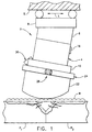
- FIG. 1 is an assembly drawing of a booted ultrasonic transducer in accordance with a first preferred embodiment of the invention, the transducer being shown in contact with but not pressed against the surface of an object to be inspected.
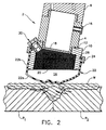
- FIG. 2 is a sectional view of the booted transducer shown in FIG. 1, but with the transducer pressed against the object surface.
- FIG. 3 is a sectional view of a booted ultrasonic transducer in accordance with a second preferred embodiment of the invention, the transducer being shown in contact with but not pressed against the surface of an object to be inspected.
- booted ultrasonic transducer 2 has an oversized transducer housing 4.
- the transducer housing 4 has a threaded radial bore for receiving a threaded connector 16, through which passes electrical wiring (not shown).
- a piezoelectric element 18 is fitted into the bottom of the transducer housing 4.
- the aforementioned electrical wiring is soldered to connect piezoelectric element 18 to pulser and receiver circuits (not shown). Damping material is added as a backing to the piezoelectric element before finalizing the assembly.
- the transducer housing is then sealed to prevent the intrusion of liquids.
- the transducer housing 4 is threaded at both the top and bottom ends.
- An incident angle wedge 6 is threadably coupled to the top end of transducer housing 4.
- the incident angle wedge 6 acts as the mounting plate for attaching the transducer assembly to the rolling carriage 8 of an automated scanner.
- Carriage 8 is generally depicted in FIG. 1 as being displaceable over a support surface S along a longitudinal axis L which lies parallel to the longitudinal axis of a welded pipe coupling, e.g., circular cylindrical pipes P1 and P2 joined by a circumferential weld W.
- the support surface S is itself rotatable about the longitudinal axis of the pipe coupling to effect circumferential scanning of the circumferential weld W.
- the angle of refraction within a given material is controlled by the ultrasonic transducer's angle of incidence, i.e., the number of degrees by which the path of propagation is tilted relative to an axis normal to the object surface.
- Snell's Law describes wave behavior at an interface between two different media. Although originally derived for light rays, Snell's Law equally applies to acoustic sound (including ultrasound) waves and many other types of waves. The law applies even if mode conversion takes place.
- the angle of incidence may be 0°, in which case the angle of refraction within the material being examined is also 0°.
- FIGS. 1 and 2 depict a transducer in which the angle of inclination of wedge 6, and consequently the angle of incidence of transducer 2, is 10°.
- FIG. 3 shows an alternative preferred embodiment in which the angle of inclination of wedge 6', and consequently the angle of incidence of transducer 2', is 0°.
- the inclination of the incident angle wedge may be machined to any angle normally associated with ultrasonic testing.
- the desired angle of incidence depends on the specific liquid couplant used to fill the transducer.
- the acoustic velocity of the liquid couplant corresponds to V 1 of Snell's Law.
- liquid couplant is water and the desired angle of refraction in mild steel is 43°, then the inclination of the wedge would be machined to an angle of 10°.
- a 10° angle of incidence will produce both a 43° refracted longitudinal wave beam and a 22.1° refracted shear wave beam.
- the angle of inclination is machined into the top surface of the wedge that attaches to carriage 8 of the scanning device.
- the carriage of the scanning device moves in parallel with respect to the sound beam entry surface of the object being inspected, carrying the transducer across the sound beam entry surface in a controlled raster scanning manner.
- transducer housing 4 serves to attach a liquid couplant housing 10 to the transducer.
- the portion of transducer housing 4 extending between the top and bottom threads has an outer radius which is greater than the outer radii of the threaded portions.
- the lower edge of the wider transducer housing portion forms a shoulder which abuts the top surface of liquid couplant housing 10.
- the shoulder serves to compress an O-ring seal 12 arranged in an annular groove formed in the top surface of liquid couplant housing 10 when the transducer housing and liquid couplant housing are tightened together. Seal 12 prevents leakage of liquid couplant through the interface between transducer housing 4 and liquid couplant housing 10.
- the liquid couplant housing 10 has first and second threaded bores of different diameter.
- the first threaded bore of relatively smaller diameter threadably engages the threaded bottom end of transducer housing 4.
- the second threaded bore of relatively larger diameter forms an ultrasound propagation channel 20.
- Propagation channel 20 is coated with sound-absorbing material to damp ultrasonic reverberations.
- the liquid coupling housing is cut at an angle which is the same as or less than the angle of inclination of the incident angle wedge.
- the propagation channel 20 is in fluid communication with a liquid couplant-filled chamber 14 formed by an angled transducer boot 22.
- Channel 20 and chamber 14 are filled with liquid couplant via a valve 30 of the type used on bicycle tires.
- Valve 30 is coupled to a liquid pump which pumps in the liquid couplant. Any gas trapped inside chamber 14 or channel 20 can form a gap that blocks propagation of the ultrasound through the liquid couplant.
- the transducer is tipped so that gases rise into the space immediately proximate to the inlet of valve 30. The valve is then opened to bleed off the air.
- the angled transducer boot 22 is a flexible and wear-resistant membrane made of a molded plastic which is transparent to ultrasound. In the event that the liquid couplant inside chamber 14 and channel 20 is oil, the plastic material must also be resistant to decomposition by oil.
- the angled transducer boot 22 is molded to have a curved concave contact surface 22a integrally joined on its periphery to a circular cylindrical wall 22b. The longitudinal dimension of wall 22b varies around its circumference, the difference between the maximum and minimum lengths being a function of the angle of inclination of wedge 6.
- the circular cylindrical wall 22b has an inner radius slightly greater than the outer radius of liquid couplant housing 10.
- the wall 22b is slid over liquid couplant housing 10 and then clamped thereon using a conventional hose clamp 24 held together by a nut and bolt assembly 26.
- a fixed-diameter slip ring made of metal or plastic can be used to clamp the transducer boot onto the liquid couplant housing.
- the preferred hose clamp is plastic device having opposing toothed jaws which interlock, the teeth being angled to slide over one another and then snap into place as the hose clamp is squeezed onto the transducer using a special hand tool.
- An O-ring seal 28 is received in an annular groove machined into the outer circumferential surface of liquid couplant housing 10. The O-ring seal 28 is compressed in the annular groove as clamp 24 is tightened. Seal 28 prevents leakage of liquid couplant through the interface between transducer boot 22 and liquid couplant housing 10.
- the concave contact surface 22a flexes inwardly to conform to the contour of the uneven surface to an extent which is dependent on the flexibility of the plastic material.
- this conformance of the transducer boot 22 to the object surface eliminates air gaps or reduces their size, thereby enhancing the bidirectional ultrasonic coupling between the transducer and the object being inspected.
- the ultrasonic transducer shown in FIG. 2 is configured to produce a central ray sound beam of 43° in mild steel.
- a straight beam configuration in accordance with a second preferred embodiment is shown in FIG. 3.
- the central ray sound beam enters the object at a 90° angle and there is no refraction.
- the embodiment of FIG. 3 has an incident angle wedge 6' with an angle of inclination of 0°, a straight transducer boot 22', and a liquid couplant housing 10' with an angle of inclination of 0°.
- the straight transducer boot 22' is a flexible and wear-resistant membrane made of plastic molded to have a curved concave contact surface 22a' integrally joined on its periphery to a circular cylindrical wall 22b'.
- the longitudinal dimension of wall 22b is constant around its circumference.
- the remaining components are the same as those incorporated in the first preferred embodiment and bear the same reference numerals.
- the angle of inclination of the incident angle wedge may be selected to produce any desired angle of refraction, including but not limited to the exemplary 43° angle described above. All such variations and modifications are intended to be encompassed by the claims set forth hereinafter.
Landscapes
- Physics & Mathematics (AREA)
- Health & Medical Sciences (AREA)
- Life Sciences & Earth Sciences (AREA)
- Chemical & Material Sciences (AREA)
- Analytical Chemistry (AREA)
- Biochemistry (AREA)
- General Health & Medical Sciences (AREA)
- General Physics & Mathematics (AREA)
- Immunology (AREA)
- Pathology (AREA)
- Acoustics & Sound (AREA)
- Investigating Or Analyzing Materials By The Use Of Ultrasonic Waves (AREA)
- Transducers For Ultrasonic Waves (AREA)
Applications Claiming Priority (2)
| Application Number | Priority Date | Filing Date | Title |
|---|---|---|---|
| US08/092,860 US5426980A (en) | 1993-07-19 | 1993-07-19 | Booted ultrasonic transducer |
| US92860 | 1998-06-08 |
Publications (2)
| Publication Number | Publication Date |
|---|---|
| EP0635719A2 true EP0635719A2 (de) | 1995-01-25 |
| EP0635719A3 EP0635719A3 (de) | 1995-12-13 |
Family
ID=22235520
Family Applications (1)
| Application Number | Title | Priority Date | Filing Date |
|---|---|---|---|
| EP94305030A Withdrawn EP0635719A3 (de) | 1993-07-19 | 1994-07-08 | Ultraschallübertrager mit einer Schutzkappe. |
Country Status (4)
| Country | Link |
|---|---|
| US (1) | US5426980A (de) |
| EP (1) | EP0635719A3 (de) |
| JP (1) | JPH07167845A (de) |
| TW (1) | TW317513B (de) |
Cited By (9)
| Publication number | Priority date | Publication date | Assignee | Title |
|---|---|---|---|---|
| DE19509290C1 (de) * | 1995-03-15 | 1996-05-02 | Bbc Reaktor Gmbh | Prüfkopf zum Ultraschallprüfen einer eingebauten Innenmehrkantschraube |
| WO2004019028A3 (en) * | 2002-08-21 | 2005-02-17 | Battelle Memorial Institute | Device for acoustic inspection of container content |
| FR2862518A1 (fr) * | 2003-11-26 | 2005-05-27 | Ge Med Sys Global Tech Co Llc | Sonde a ultrasons |
| WO2005119242A1 (de) * | 2004-06-01 | 2005-12-15 | Siemens Aktiengesellschaft | Verfahren und vorrichtung zur ermittlung von defekten in einer turbinenschaufel |
| DE102004059086A1 (de) * | 2004-12-08 | 2006-06-14 | Robert Bosch Gmbh | Vorrichtung und Verfahren zum Prüfen eines Prüflings |
| WO2019226247A1 (en) * | 2018-05-22 | 2019-11-28 | Baker Hughes, A Ge Company, Llc | Signal transmission system and method |
| WO2020076605A3 (en) * | 2018-10-09 | 2020-05-22 | Hollister Incorporated | Ostomy appliance configured for leakage detection |
| NL2023144B1 (en) * | 2019-05-15 | 2020-12-01 | Intero Integrity Services | Measurement device |
| CN118243787A (zh) * | 2024-05-30 | 2024-06-25 | 上海奉贤建设发展(集团)有限公司 | 一种碳纤维混凝土质量超声检测装置 |
Families Citing this family (33)
| Publication number | Priority date | Publication date | Assignee | Title |
|---|---|---|---|---|
| US5567881A (en) * | 1995-05-05 | 1996-10-22 | Mcdonnell Douglas Corporation | Method and apparatus for inspecting a structural part having surface irregularities |
| US5948985A (en) * | 1996-05-31 | 1999-09-07 | Ormet Corporation | Method and apparatus for ultrasonic testing of aluminum billet |
| US5895744A (en) * | 1997-02-28 | 1999-04-20 | Eastman Kodak Company | Method and apparatus for making polyester web having high adhesion to coated layers |
| CA2300817A1 (en) * | 1997-08-19 | 1999-02-25 | John D. Mendlein | Ultrasonic transmission films and devices, particularly for hygienic transducer surfaces |
| US6356379B1 (en) * | 1998-12-07 | 2002-03-12 | Florida Atlantic University | Adjustable opto-acoustical low pass filter and technique |
| US6368281B1 (en) * | 1999-07-30 | 2002-04-09 | Rodney J Solomon | Two-dimensional phased array ultrasound transducer with a convex environmental barrier |
| US6578424B1 (en) * | 2000-09-27 | 2003-06-17 | Digital Wave Corporation | Hand-held variable angle membrane (VAM) ultrasonic scanning head for the noninvasive detection of corrosion, MIC and foreign objects in pipes |
| JP4444729B2 (ja) * | 2004-05-12 | 2010-03-31 | 株式会社日立製作所 | 電気機器巻線の接合部の評価方法および装置 |
| EP2004293A2 (de) * | 2006-04-07 | 2008-12-24 | Smith and Nephew, Inc. | Steuerung akustischer modi in gewebeheilungsanwendungen |
| US8127612B2 (en) * | 2008-08-25 | 2012-03-06 | Praxair Technology, Inc. | System and method for ultrasonic examination of threaded surfaces |
| US8087298B1 (en) * | 2009-03-10 | 2012-01-03 | Sandia Corporation | Ultrasonic probe deployment device for increased wave transmission and rapid area scan inspections |
| DE202009014771U1 (de) * | 2009-11-02 | 2011-03-24 | Seuthe, Ulrich | Kopplungselement zur akustischen Ankopplung eines Schallwandlers an einen Körper sowie Schallwandler |
| JP5693058B2 (ja) * | 2010-06-24 | 2015-04-01 | 大成建設株式会社 | 非破壊密度計測装置 |
| US7954387B1 (en) | 2010-08-18 | 2011-06-07 | General Electric Company | Ultrasonic transducer device |
| EP2635901B1 (de) | 2010-11-05 | 2022-04-20 | National Research Council of Canada | Verfahren zur herstellung einer flexiblen ultraschallwandlervorrichtung |
| WO2013139849A1 (en) * | 2012-03-20 | 2013-09-26 | Alstom Technology Ltd | Ultrasonic ndt sensor arrangement and method for inspecting surfaces of variable geometry of metal bodies |
| US9646599B2 (en) * | 2013-10-24 | 2017-05-09 | Spirit Aerosystems, Inc. | Remoldable contour sensor holder |
| JP6650202B2 (ja) * | 2015-02-11 | 2020-02-19 | 高周波熱錬株式会社 | 熱処理層深さ測定用超音波プローブ及び熱処理層深さの測定方法 |
| US9778231B2 (en) * | 2015-05-13 | 2017-10-03 | Spirit Aerosystems, Inc. | Ultrasonic inspection end effector |
| US12162160B2 (en) | 2016-12-23 | 2024-12-10 | Gecko Robotics, Inc. | System, apparatus and method for improved location identification with prism |
| US11307063B2 (en) | 2016-12-23 | 2022-04-19 | Gtc Law Group Pc & Affiliates | Inspection robot for horizontal tube inspection having vertically positionable sensor carriage |
| EP4404183A3 (de) | 2016-12-23 | 2024-09-25 | Gecko Robotics, Inc. | Inspektionsroboter |
| US12358141B2 (en) | 2016-12-23 | 2025-07-15 | Gecko Robotics, Inc. | Systems, methods, and apparatus for providing interactive inspection map for inspection robot |
| US10794871B1 (en) | 2018-05-23 | 2020-10-06 | The United States Of America As Represented By The Secretary Of The Air Force | Elastomer ultrasonic coupling adaptor for focused transducers |
| EP3934861B1 (de) | 2019-03-08 | 2025-02-26 | Gecko Robotics, Inc. | Prüfroboter |
| US11835485B2 (en) * | 2020-09-30 | 2023-12-05 | Baker Hughes Oilfield Operations Llc | Ultrasonic probe having flexible stabilizing element for probe alignment |
| AT524519B1 (de) * | 2020-12-01 | 2022-12-15 | Facc Ag | Ultraschall-Prüfvorrichtung |
| WO2022225725A1 (en) | 2021-04-20 | 2022-10-27 | Gecko Robotics, Inc. | Flexible inspection robot |
| US11971389B2 (en) | 2021-04-22 | 2024-04-30 | Gecko Robotics, Inc. | Systems, methods, and apparatus for ultra-sonic inspection of a surface |
| US12566158B2 (en) | 2021-04-22 | 2026-03-03 | Gecko Robotics, Inc. | Robotic systems for ultrasonic surface inspection using shaped elements |
| CN116953074B (zh) * | 2022-04-12 | 2026-01-23 | 高速铁路建造技术国家工程实验室 | 换能器组件、超声波连续检测系统和方法 |
| WO2024097795A2 (en) | 2022-11-01 | 2024-05-10 | Gecko Robotics, Inc. | Inspection robot with profile adapting sled, couplant reduction film and transducer pod for thick assets |
| WO2024138219A2 (en) | 2022-12-23 | 2024-06-27 | Gecko Robotics, Inc. | Systems, methods, and apparatus for inspection of a surface using sensor holder with dual linear phased array of ultra-sonic elements |
Family Cites Families (17)
| Publication number | Priority date | Publication date | Assignee | Title |
|---|---|---|---|---|
| US2592134A (en) * | 1945-06-28 | 1952-04-08 | Sperry Prod Inc | Method of supersonic inspection |
| FR997867A (fr) * | 1945-08-13 | 1952-01-11 | Acec | Palpeur pour examen ou traitement par ondes élastiques de corps solides |
| US2660054A (en) * | 1951-12-07 | 1953-11-24 | Sperry Prod Inc | Ultrasonic thickness measuring device |
| US2740289A (en) * | 1953-03-20 | 1956-04-03 | Sperry Prod Inc | Automatic scanning and recording device for ultrasonic inspection of materials |
| US2913602A (en) * | 1955-11-03 | 1959-11-17 | Ivan L Joy | Method and means for transmitting elastic waves |
| US3175106A (en) * | 1963-02-07 | 1965-03-23 | Automation Ind Inc | Inspection apparatus |
| US3497728A (en) * | 1967-03-20 | 1970-02-24 | Standard Oil Co | Ultrasonic inspection apparatus |
| US3628375A (en) * | 1970-04-28 | 1971-12-21 | Dominick A Pagano | Apparatus for ultrasonic inspection of a length of test material |
| FR2127137A5 (de) * | 1971-02-25 | 1972-10-13 | Centre Techn Ind Mecanique | |
| US3777552A (en) * | 1971-11-09 | 1973-12-11 | Wages C | Ultrasonic scanning system for in-place inspection of brazed tube joints |
| US4020679A (en) * | 1975-08-13 | 1977-05-03 | Automation Industries, Inc. | Sled for ultrasonic NDT system |
| US4603701A (en) * | 1983-12-16 | 1986-08-05 | Hewlett-Packard Company | Stand-off device with special fluid |
| DE8418008U1 (de) * | 1984-06-14 | 1985-10-10 | Jurid Werke Gmbh, 2056 Glinde | Prüfkopf zur zerstörungsfreien Prüfung von Werkstoffen, Werkstoffverbindungen und dgl. mittels Ultraschall |
| US4796632A (en) * | 1986-08-11 | 1989-01-10 | General Electric Company | Standoff adapter for ultrasound probe |
| DE3737593C2 (de) * | 1986-11-06 | 1995-03-16 | Toshiba Kawasaki Kk | Ultraschall-Sondenvorrichtung |
| SU1670581A1 (ru) * | 1988-03-09 | 1991-08-15 | Воронежский Политехнический Институт | Устройство дл контрол физико-механических характеристик поверхностей материалов |
| USH1290H (en) * | 1992-08-26 | 1994-02-01 | The United States Of America As Represented By The Secretary Of The Army | Conformable acoustic coupler |
-
1993
- 1993-07-19 US US08/092,860 patent/US5426980A/en not_active Expired - Fee Related
-
1994
- 1994-02-02 TW TW083100873A patent/TW317513B/zh active
- 1994-07-08 EP EP94305030A patent/EP0635719A3/de not_active Withdrawn
- 1994-07-19 JP JP6166430A patent/JPH07167845A/ja not_active Withdrawn
Cited By (17)
| Publication number | Priority date | Publication date | Assignee | Title |
|---|---|---|---|---|
| DE19509290C1 (de) * | 1995-03-15 | 1996-05-02 | Bbc Reaktor Gmbh | Prüfkopf zum Ultraschallprüfen einer eingebauten Innenmehrkantschraube |
| WO2004019028A3 (en) * | 2002-08-21 | 2005-02-17 | Battelle Memorial Institute | Device for acoustic inspection of container content |
| US6938488B2 (en) | 2002-08-21 | 2005-09-06 | Battelle Memorial Institute | Acoustic inspection device |
| FR2862518A1 (fr) * | 2003-11-26 | 2005-05-27 | Ge Med Sys Global Tech Co Llc | Sonde a ultrasons |
| US7987721B2 (en) | 2004-06-01 | 2011-08-02 | Siemens Aktiengesellschaft | Method and device for determining defects in a turbine blade |
| EP1610122A1 (de) * | 2004-06-01 | 2005-12-28 | Siemens Aktiengesellschaft | Verfahren und Vorrichtung zur Ermittlung von Defekten in einer Turbinenschaufel mittels eines Ultraschall-Gruppenstrahlers |
| JP2008501109A (ja) * | 2004-06-01 | 2008-01-17 | シーメンス アクチエンゲゼルシヤフト | タービン翼の探傷方法と装置 |
| WO2005119242A1 (de) * | 2004-06-01 | 2005-12-15 | Siemens Aktiengesellschaft | Verfahren und vorrichtung zur ermittlung von defekten in einer turbinenschaufel |
| DE102004059086A1 (de) * | 2004-12-08 | 2006-06-14 | Robert Bosch Gmbh | Vorrichtung und Verfahren zum Prüfen eines Prüflings |
| WO2019226247A1 (en) * | 2018-05-22 | 2019-11-28 | Baker Hughes, A Ge Company, Llc | Signal transmission system and method |
| US10958358B2 (en) | 2018-05-22 | 2021-03-23 | Baker Hughes, A Ge Company, Llc | Signal transmission system and method |
| AU2022268380B2 (en) * | 2018-05-22 | 2024-02-29 | Baker Hughes Holdings Llc | Signal transmission system and method |
| WO2020076605A3 (en) * | 2018-10-09 | 2020-05-22 | Hollister Incorporated | Ostomy appliance configured for leakage detection |
| US11202719B2 (en) | 2018-10-09 | 2021-12-21 | Hollister Incorporated | Ostomy appliance configured for leakage detection |
| US12295874B2 (en) | 2018-10-09 | 2025-05-13 | Hollister Incorporated | Ostomy appliance configured for leakage detection |
| NL2023144B1 (en) * | 2019-05-15 | 2020-12-01 | Intero Integrity Services | Measurement device |
| CN118243787A (zh) * | 2024-05-30 | 2024-06-25 | 上海奉贤建设发展(集团)有限公司 | 一种碳纤维混凝土质量超声检测装置 |
Also Published As
| Publication number | Publication date |
|---|---|
| EP0635719A3 (de) | 1995-12-13 |
| TW317513B (de) | 1997-10-11 |
| US5426980A (en) | 1995-06-27 |
| JPH07167845A (ja) | 1995-07-04 |
Similar Documents
| Publication | Publication Date | Title |
|---|---|---|
| US5426980A (en) | Booted ultrasonic transducer | |
| US9091638B2 (en) | Apparatus and method for non-destructive testing using ultrasonic phased array | |
| US4165649A (en) | Apparatus and method for ultrasonic inspection of highly attenuative materials | |
| US5460046A (en) | Method and apparatus for ultrasonic pipeline inspection | |
| US4658649A (en) | Ultrasonic method and device for detecting and measuring defects in metal media | |
| US4735097A (en) | Method and apparatus for measuring fluid characteristics using surface generated volumetric interrogation signals | |
| EP0177053B1 (de) | Verfahren zur Feststellung von Fehlern in einem dickwandigen Stahlrohr mittels einer Ultraschallwinkelprüftechnik und Vorrichtung dazu | |
| US5497662A (en) | Method and apparatus for measuring and controlling refracted angle of ultrasonic waves | |
| US7694569B2 (en) | Phased array ultrasonic water wedge apparatus | |
| HUE030441T2 (en) | Ultrasonic non-destructive testing | |
| US5665893A (en) | Reference block for determining operating characteristics of ultrasonic transducer in right circular cylinder type probe | |
| US20090249879A1 (en) | Inspection systems and methods for detection of material property anomalies | |
| EP0997731A2 (de) | Verfahren zur Bestimmung der Qualität des Verbindens zwischen zwei metallischen Rohren | |
| Fei et al. | Simultaneous velocity, thickness and profile imaging by ultrasonic scan | |
| US5377237A (en) | Method of inspecting repaired stub tubes in boiling water nuclear reactors | |
| US3832889A (en) | Ultra-sonic weld inspection device | |
| US5419195A (en) | Ultrasonic booted head probe for motor bore inspection | |
| CA2012374C (en) | Ultrasonic crack sizing method | |
| US3299695A (en) | Ultrasonic testing apparatus | |
| US11592424B2 (en) | System for detecting flooding in flexible tubular pipes under high pressure conditions | |
| US7334479B2 (en) | Systems and methods for non-contact measuring sputtering target thickness ultrasonics | |
| Willems et al. | Internal Inspection Device for Detection of Longitudinal Cracks in Oil and Gas Pipelines: Results From an Operational Experience | |
| JP3702129B2 (ja) | 超音波探傷装置 | |
| WO2000055594A2 (en) | Ultrasonic delays for use in explosive environments | |
| Johansen et al. | Ultrasonic Well Integrity Logging Using Phased Array Technology |
Legal Events
| Date | Code | Title | Description |
|---|---|---|---|
| PUAI | Public reference made under article 153(3) epc to a published international application that has entered the european phase |
Free format text: ORIGINAL CODE: 0009012 |
|
| AK | Designated contracting states |
Kind code of ref document: A2 Designated state(s): CH ES LI SE |
|
| PUAL | Search report despatched |
Free format text: ORIGINAL CODE: 0009013 |
|
| AK | Designated contracting states |
Kind code of ref document: A3 Designated state(s): CH ES LI SE |
|
| 17P | Request for examination filed |
Effective date: 19960613 |
|
| STAA | Information on the status of an ep patent application or granted ep patent |
Free format text: STATUS: THE APPLICATION HAS BEEN WITHDRAWN |
|
| 18W | Application withdrawn |
Withdrawal date: 19960730 |