EP0635239A1 - Method and apparatus for manufacturing electrodes - Google Patents
Method and apparatus for manufacturing electrodes Download PDFInfo
- Publication number
- EP0635239A1 EP0635239A1 EP94107021A EP94107021A EP0635239A1 EP 0635239 A1 EP0635239 A1 EP 0635239A1 EP 94107021 A EP94107021 A EP 94107021A EP 94107021 A EP94107021 A EP 94107021A EP 0635239 A1 EP0635239 A1 EP 0635239A1
- Authority
- EP
- European Patent Office
- Prior art keywords
- web
- label
- labels
- carrier material
- adhesive
- Prior art date
- Legal status (The legal status is an assumption and is not a legal conclusion. Google has not performed a legal analysis and makes no representation as to the accuracy of the status listed.)
- Granted
Links
Images
Classifications
-
- A—HUMAN NECESSITIES
- A61—MEDICAL OR VETERINARY SCIENCE; HYGIENE
- A61B—DIAGNOSIS; SURGERY; IDENTIFICATION
- A61B5/00—Measuring for diagnostic purposes; Identification of persons
- A61B5/24—Detecting, measuring or recording bioelectric or biomagnetic signals of the body or parts thereof
- A61B5/25—Bioelectric electrodes therefor
- A61B5/251—Means for maintaining electrode contact with the body
- A61B5/257—Means for maintaining electrode contact with the body using adhesive means, e.g. adhesive pads or tapes
-
- A—HUMAN NECESSITIES
- A61—MEDICAL OR VETERINARY SCIENCE; HYGIENE
- A61B—DIAGNOSIS; SURGERY; IDENTIFICATION
- A61B5/00—Measuring for diagnostic purposes; Identification of persons
- A61B5/24—Detecting, measuring or recording bioelectric or biomagnetic signals of the body or parts thereof
- A61B5/25—Bioelectric electrodes therefor
- A61B5/263—Bioelectric electrodes therefor characterised by the electrode materials
- A61B5/266—Bioelectric electrodes therefor characterised by the electrode materials containing electrolytes, conductive gels or pastes
-
- A—HUMAN NECESSITIES
- A61—MEDICAL OR VETERINARY SCIENCE; HYGIENE
- A61B—DIAGNOSIS; SURGERY; IDENTIFICATION
- A61B2562/00—Details of sensors; Constructional details of sensor housings or probes; Accessories for sensors
- A61B2562/12—Manufacturing methods specially adapted for producing sensors for in-vivo measurements
- A61B2562/125—Manufacturing methods specially adapted for producing sensors for in-vivo measurements characterised by the manufacture of electrodes
Definitions
- the invention relates to a method for producing electrodes, in particular EKG electrodes, in which labels are glued onto the top of a web-shaped carrier material, connecting elements being connected to the labels and finally individual electrodes made from the web-shaped carrier material with the labels and the connecting elements glued on one after the other each formed with a label and connecting element, preferably punched out.
- the invention further relates to a device for performing such a method.
- the object of the invention is to provide an economical method for the precise manufacture of electrodes.
- a device for performing this method is to be created.
- thermo-activatable adhesives are adhesives that only become sticky when exposed to heat, but are not self-adhesive at room temperatures. When cooled to normal temperature, these adhesives maintain the firm connection, but are no longer sticky in places where no such firm connection has been established.
- hot melt adhesives hot melt adhesives
- the label webs coated in this way are not self-adhesive at room temperature, but can be thermally activated by heating.
- Another thermally activated adhesive can be, for example, a dispersion adhesive.
- the label web is coated with a dispersion from use in the method according to the invention. The solvent evaporates. What remains is an adhesive layer on the label web, which is not self-adhesive but only becomes sticky when exposed to heat.
- other thermally activated adhesives are also conceivable and possible.
- the material web of the carrier material is precisely positioned directly under the hole of the label punch, the punched-out label is accurate to 0.1 mm, for example, on the heated material web pressed and glued to it. Since the thermo-activatable adhesive cools down again immediately (in contrast to self-adhesive labels, which are always sticky), it is no longer sticky in exposed positions in the following stations and can therefore come into contact with machine parts without problems.
- Another advantage is the fact that the known self-adhesive labels can only be obtained from another manufacturer as a whole or can only be produced with great effort.
- the electrode manufacturer himself can provide the adhesive with the adhesive in a cost-effective manner, for example from PVC or another plastic.
- Storage is also simplified, since basically the same tape can be used for different label sizes and shapes, since the final shape of the label is only determined shortly before it is applied to the web-shaped carrier material, for example in a label punch. A storage of similar label webs is therefore sufficient for the production of a variety of different labels.
- thermo-activatable adhesives which are not tacky at room temperatures can also be used to print the labels in the device for producing the electrodes themselves. It is therefore only necessary to feed in a single-colored (for example white) tape, from which the labels are then punched and applied to the web-shaped carrier material. The labels then cool down immediately and can therefore be easily printed on, with the base which is generally required for printing and which is glued through a hole in the adhesive web-shaped carrier material comes into contact, does not stick to the labels in an undesirable manner, as would be the case, for example, with self-adhesive labels.
- a single-colored (for example white) tape from which the labels are then punched and applied to the web-shaped carrier material.
- the labels then cool down immediately and can therefore be easily printed on, with the base which is generally required for printing and which is glued through a hole in the adhesive web-shaped carrier material comes into contact, does not stick to the labels in an undesirable manner, as would be the case, for example, with self-adhesive labels.
- the storage is further simplified, since it is not necessary to keep differently printed labels in stock, but only a neutral tape, which is provided on the underside with a thermally activated adhesive.
- the printing which can be easily adapted to customer requirements, is then carried out in the machine itself after the labels have already been applied to the web-shaped carrier material.
- the invention also relates to a device for carrying out the method with a guiding and conveying device for the web-shaped carrier material, which is characterized by a label application device for forming, preferably punching out labels from a tape coated with thermally activated adhesive and for applying the same to the carrier material, whereby a heating device for heating the adhesive is arranged in the area of the label application device.
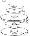
- FIG. 1 shows an exploded view of an electrode which can be produced economically and precisely using the method according to the invention.
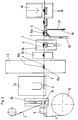
- Fig. 2 shows an embodiment of an apparatus for performing the method according to the invention.
- the electrode shown in an exploded view in FIG. 1 has a carrier material 1, for example made of foam, fabric or fleece.
- the disk-shaped carrier material has a self-adhesive layer 2 on its underside, which is covered at the edge by a small cover.
- This small cover 3 makes it easier to pull off a cover 4 which covers the self-adhesive layer 2 before the electrode is used and which is pulled off just before the electrode is stuck to the patient's skin in order to expose the self-adhesive layer 2.
- the disk-shaped carrier material has a circular hole 1a in the middle. This hole is from above through a label 4, for example made of PVC or a other plastic covered.
- the label 4 is connected to the carrier material 1 via a hot melt adhesive 5.
- the label 4 can advantageously be printed on its upper side. It is primarily used for the secure mounting of a connection element, which here consists of a metal rivet.
- the upper part of the rivet 6a and the lower part of the rivet 6b are riveted together through the label and thus secured in a positionally secure manner.
- a sponge 7 which is glued to the hot melt adhesive 5.
- the sponge 7 is impregnated with a conductive gel in a manner known per se for electrical potential transmission.
- the web-shaped carrier material rolled off from a roll 8 is moved through the device from left to right in FIG. 2.
- a cyclical transport takes place, with known guiding and conveying devices not being shown for the sake of clarity.
- the carrier material consists, for example, of a 35 to 80 mm wide self-adhesive coated foam, non-woven fabric or the like, the self-adhesive layer underneath of which is covered with siliconized paper.
- a circular hole for example 15 to 25 mm in size, is punched out of the sheet-like carrier material in the center of a punch 9.
- a continuous web 4 ′ coated with thermally activated adhesive for example hot melt adhesive
- this label application device is designed as a punching device 10, which successively cuts out 4 'labels 4 on the web and presses them onto the carrier material in one operation.
- heating of the hot-melt adhesive on the underside of the labels is necessary in the area of the label application device 10, since this would otherwise not be tacky at room temperatures.
- a heating device 11 is provided, which heats the web-shaped carrier material 1 from below. Due to the heat, the hot melt adhesive adheres intimately to the web-shaped carrier material.
- the punching and subsequent pressing make it possible to position the label extremely precisely on the web-shaped carrier material.
- the label glued to the web-shaped carrier material 1 is printed. It is particularly advantageous that a suitable distance between the printing station 12 and the label application device 10 and a suitable transport speed of the web-shaped carrier material means that the hot melt adhesive in the printing station 12 is no longer sticky. This means that the exposed areas of adhesive cannot stick to a base that only allows printing from above.
- the label webs with the most varied customer prints must be kept in large quantities, since a larger quantity of labels must always be present for each customer order in order to be able to replace any rejects.
- printing can take place inline, the label quantity corresponds exactly to the order quantity, when changing an order the label web is not changed, but only the printing plate.
- the rivet parts 6a and 6b are riveted together through the label 4 and then form the electrical connection element. It is also of great advantage here that the hot melt adhesive layer is not sticky.
- a sponge 7 is now to be connected to the label 4 in a sponge punch 14 from below. Since the hot melt adhesive is not tacky at room temperature, the sponge punch 14 is preceded by a heating station 15 which heats the exposed areas of the hot melt adhesive on the underside of the labels 4 by means of hot air and thus activates them for gluing. Due to the small distance between the stations 15 and 14, the heating is maintained, for example, over one cycle of the machine, so that the sponge 7 can be reliably stuck to the label 4.
- the finished electrodes are punched out of the web-shaped carrier material in the Fergtig punch 18. They fall out of the device in the direction of arrow 19.
- thermo-activatable adhesives in particular dispersion adhesives, can be used which are not self-adhesive at room temperature but become sticky when exposed to heat.
Abstract
Description
Die Erfindung betrifft ein Verfahren zur Herstellung von Elektroden, insbesondere EKG-Elektroden, bei dem auf die Oberseite eines bahnförmigen Trägermaterials Etiketten aufgeklebt werden, wobei Anschlußelemente mit den Etiketten verbunden werden und schließlich aus dem bahnförmigen Trägermaterial mit den hintereinander aufgeklebten Etiketten und den Anschlußelementen einzelne Elektroden mit jeweils einem Etikett und Anschlußelement gebildet, vorzugsweise ausgestanzt werden. Weiters betrifft die Erfindung eine Vorrichtung zur Durchführung eines solchen Verfahrens.The invention relates to a method for producing electrodes, in particular EKG electrodes, in which labels are glued onto the top of a web-shaped carrier material, connecting elements being connected to the labels and finally individual electrodes made from the web-shaped carrier material with the labels and the connecting elements glued on one after the other each formed with a label and connecting element, preferably punched out. The invention further relates to a device for performing such a method.
Alle herkömmlichen Verfahren verwenden als Etiketten solche, welche mit einer selbstklebenden Schicht versehen sind. Diese müssen, da selbstklebend, auf einer silikonisierten Trägerschicht zugeführt werden. Um diese Etiketten "spenden" zu können, müssen sie vorher in einem separaten Arbeitsgang angestanzt und das Stanzgitter abgezogen werden. Das Trägerband der Etiketten wird dann in der Elektrodenmaschine um eine scharfe Kante gezogen, dadurch springt das Etikett ab und kann auf die Materialbahn gedrückt werden. Dieses Verfahren hat mehrere wesentliche Nachteile. Die Positionierung auf der Materialbahn kann insbesondere in Längsrichtung nicht ganz genau eingehalten werden. Fehler in dem vorher fertiggestellten Etikettenband werden zu Fehlern auf der Materialbahn. Besonders wichtig aber ist, daß die freiliegende Selbstklebeschicht nicht mehr mit Maschinenteilen in Berührung kommen darf, da diese sonst festklebt. Insbesonders bedeutsam ist dies, wenn der Etikettenbereich inline bedruckt werden soll, da dies eine Gegendruckplatte zur Voraussetzung hat, an welcher das selbstklebende Etikett festkleben würde.All conventional methods use as labels those which are provided with a self-adhesive layer. Since they are self-adhesive, they have to be fed onto a siliconized carrier layer. In order to be able to "donate" these labels, they must first be punched in a separate operation and the lead frame removed. The label carrier tape is then pulled around a sharp edge in the electrode machine, which causes the label to snap off and can be pressed onto the material web. This process has several major disadvantages. The positioning on the material web cannot be exactly adhered to, particularly in the longitudinal direction. Faults in the label tape previously completed become defects on the material web. It is particularly important, however, that the exposed self-adhesive layer must no longer come into contact with machine parts, otherwise they will stick. This is particularly important if the label area is to be printed inline, since this requires a counter-pressure plate to which the self-adhesive label would stick.
Aufgabe der Erfindung ist es, ein wirtschaftliches Verfahren zur präzisen Herstellung von Elektroden anzugeben. Außerdem soll eine Vorrichtung zur Durchführung dieses Verfahrens geschaffen werden.The object of the invention is to provide an economical method for the precise manufacture of electrodes. In addition, a device for performing this method is to be created.
Dies wird erfindungsgemäß durch die Merkmale des Anspruchs 1 (Verfahren) bzw. des Anspruchs 17 (Vorrichtung) gelöst.According to the invention, this is solved by the features of claim 1 (method) and claim 17 (device).
Als thermoaktivierbare Klebstoffe eignen sich Klebstoffe, die erst bei Wärmeeinwirkung klebrig werden, bei Raumtemperaturen aber nicht selbstklebend sind. Bei Abkühlung auf Normaltemperatur halten diese Klebstoffe zwar die feste Verbindung aufrecht, sind aber nicht mehr klebrig an Stellen, wo keine derartige feste Verbindung aufgebaut wurde. Beispielsweise eignen sich Schmelzklebstoffe (Hotmelt-Klebstoffe), die vorher aus der Schmelze auf die Etikettenbahn aufgebracht werden. Nach dem Aufbringen und Abkühlen der Schmelze sind die so beschichteten Etikettenbahnen bei Raumtemperatur nicht selbstklebend, aber durch Erwärmen thermoaktivierbar. Ein anderer thermoaktivierbarer Kleber kann beispielsweise ein Dispersionskleber sein. Hier wird die Etikettenbahn von der Verwendung im erfindungsgemäßen Verfahren mit einer Dispersion beschichtet. Das Lösungsmittel verdunstet. Zurück bleibt eine Klebstoffschicht auf der Etikettenbahn, die nicht selbstklebend ist, sondern erst durch Wärmeeinwirkung klebrig wird. Grundsätzlich sind auch noch weitere thermoaktivierbare Klebstoffe denkbar und möglich.Suitable thermo-activatable adhesives are adhesives that only become sticky when exposed to heat, but are not self-adhesive at room temperatures. When cooled to normal temperature, these adhesives maintain the firm connection, but are no longer sticky in places where no such firm connection has been established. For example, hot melt adhesives (hot melt adhesives) that are previously applied from the melt to the label web are suitable. After the melt has been applied and cooled, the label webs coated in this way are not self-adhesive at room temperature, but can be thermally activated by heating. Another thermally activated adhesive can be, for example, a dispersion adhesive. Here the label web is coated with a dispersion from use in the method according to the invention. The solvent evaporates. What remains is an adhesive layer on the label web, which is not self-adhesive but only becomes sticky when exposed to heat. In principle, other thermally activated adhesives are also conceivable and possible.
Das erfindungsgemäße Verfahren weist zahlreiche Vorteile auf: Die Materialbahn des Trägermaterials liegt genau positioniert unmittelbar unter dem Loch der Etikettenstanze, das ausgestanzte Etikett wird auf beispielsweise 0,1 mm genau auf die erwärmte Materialbahn gepreßt und mit dieser verklebt. Da der thermoaktivierbare Klebstoff sofort wieder auskühlt, ist er (im Gegensatz zu selbstklebenden Etiketten, die immer klebrig sind) in den folgenden Stationen an freiliegenden Stellen nicht mehr klebrig und kann daher ohne Probleme mit Maschinenteilen in Berührung kommen.The method according to the invention has numerous advantages: the material web of the carrier material is precisely positioned directly under the hole of the label punch, the punched-out label is accurate to 0.1 mm, for example, on the heated material web pressed and glued to it. Since the thermo-activatable adhesive cools down again immediately (in contrast to self-adhesive labels, which are always sticky), it is no longer sticky in exposed positions in the following stations and can therefore come into contact with machine parts without problems.
Ein weiterer Vorteil ist darin zu sehen, daß die bekannten selbstklebenden Etiketten nur von einem weiteren Hersteller als Ganzes bezogen werden können bzw. nur mit hohem Aufwand selber hergestellt werden können. Durch die Verwendung eines thermoaktivierbaren Klebstoffs können Bahnen, beispielsweise aus PVC oder einem anderen Kunststoff vom Elektrodenhersteller selbst auf kostengünstige Art und Weise mit dem Klebstoff versehen werden. Auch die Lagerhaltung ist vereinfacht, da für verschiedene Etikettengrößen und Formen grundsätzlich dasselbe Band verwendet werden kann, da ja die endgültige Form der Etiketten erst kurz vor dem Aufbringen auf das bahnförmige Trägermaterial, beispielsweise in einer Etikettenstanze festgelegt wird. Damit reicht eine Lagerhaltung von gleichartigen Etikettenbahnen für die Herstellung einer Vielzahl verschiedener Etiketten aus.Another advantage is the fact that the known self-adhesive labels can only be obtained from another manufacturer as a whole or can only be produced with great effort. By using a thermally activated adhesive, the electrode manufacturer himself can provide the adhesive with the adhesive in a cost-effective manner, for example from PVC or another plastic. Storage is also simplified, since basically the same tape can be used for different label sizes and shapes, since the final shape of the label is only determined shortly before it is applied to the web-shaped carrier material, for example in a label punch. A storage of similar label webs is therefore sufficient for the production of a variety of different labels.
Besonders vorteihaft kann durch die Verwendung von bei Raumtemperaturen nicht klebrigen, thermoaktivierbaren Klebstoffen auch ein Bedrucken der Etiketten in der Vorrichtung für die Herstellung der Elektroden selbst vorgenommen werden. Es braucht also nur ein einfarbiges (beispielsweise weißes) Band zugeführt werden, aus dem dann die Etiketten gestanzt und auf das bahnförmige Trägermaterial aufgebracht werden. Danach kühlen die Etiketten sofort aus und können daher leicht bedruckt werden, wobei die für einen Druck im allgemeinen nötige Unterlage, welche mit dem Klebstoff durch ein Loch im bahnförmigen Trägermaterial in Berührung kommt, nicht auf unerwünschte Weise mit den Etiketten verklebt, wie dies beispielsweise von selbstklebenden Etiketten der Fall wäre. Durch das Bedrucken der Etiketten in der Maschine selbst wird die Lagerhaltung weiters vereinfacht, da nicht verschiedenartig bedruckte Etiketten auf Lager gehalten werden müssen, sondern eben nur ein neutrales Band, das an seiner Unterseite mit einem thermoaktivierbaren Klebstoff versehen ist. Die den Kundenwünschen leicht anpaßbare Bedruckung erfolgt dann in der Maschine selbst, nachdem die Etiketten bereits auf das bahnförmige Trägermaterial aufgebracht worden sind.Particularly advantageously, the use of thermo-activatable adhesives which are not tacky at room temperatures can also be used to print the labels in the device for producing the electrodes themselves. It is therefore only necessary to feed in a single-colored (for example white) tape, from which the labels are then punched and applied to the web-shaped carrier material. The labels then cool down immediately and can therefore be easily printed on, with the base which is generally required for printing and which is glued through a hole in the adhesive web-shaped carrier material comes into contact, does not stick to the labels in an undesirable manner, as would be the case, for example, with self-adhesive labels. By printing the labels in the machine itself, the storage is further simplified, since it is not necessary to keep differently printed labels in stock, but only a neutral tape, which is provided on the underside with a thermally activated adhesive. The printing, which can be easily adapted to customer requirements, is then carried out in the machine itself after the labels have already been applied to the web-shaped carrier material.
Für das Aufbringen der Etiketten auf das bahnförmige Trägermaterial bestehen mehrere Möglichkeiten. Zunächst besteht die Möglichkeit vorgefertigte Einzeletiketten zu verwenden, die an ihrer Unterseite mit thermoaktivierbarem Klebstoff beschichtet sind. Um die automatisierte Zufuhr der Etiketten zu erleichtern, ist es besonders günstig, wenn die Etiketten in Form einer durchgehenden, unten mit thermoaktivierbarem Klebstoff beschichteten Bahn zugeführt werden. Es gibt dann bei einer solchen Bahnzufuhr zwei Möglichkeiten. Entweder man bildet aus der Bahn kurz vor dem Aufkleben auf das Trägermaterial einzelne Etiketten (beispielsweise durch Stanzen) und klebt dann diese Einzeletiketten auf. Es gibt aber auch die Möglichkeit, die Etikettenbahn als Ganzes aufzukleben und die Etiketten erst später zu bilden, insbesondere dann, wenn das Trägermaterial zur Bildung der einzelnen Elektroden abgeschnitten bzw. ausgestanzt wird. Gleichzeitig mit diesem Schneide- oder Stanzprozess kann dann auch die auf dem Trägermaterial aufgeklebte Etikettenbahn mitgeschnitten bzw. mitgestanzt werden.There are several options for applying the labels to the web-shaped carrier material. First of all, there is the possibility of using pre-made individual labels that are coated on the underside with thermo-activatable adhesive. In order to facilitate the automated feeding of the labels, it is particularly favorable if the labels are fed in the form of a continuous web which is coated at the bottom with thermally activated adhesive. There are then two options for such a web feed. Either you form individual labels from the web shortly before sticking them onto the carrier material (for example by punching) and then stick these individual labels on. However, there is also the possibility of sticking on the label web as a whole and forming the labels later, in particular when the carrier material is cut or punched out to form the individual electrodes. Simultaneously with this cutting or punching process, the label web glued onto the carrier material can also be cut or punched.
Die Erfindung betrifft auch eine Vorrichtung zur Durchführung des Verfahrens mit einer Führungs- und Fördervorrichtung für das bahnförmige Trägermaterial, welche gekennzeichnet ist durch eine Etikettenaufbringevorrichtung zum Bilden, vorzugsweise Ausstanzen von Etiketten aus einem mit thermoaktivierbarem Klebstoff beschichteten Band und zum Aufbringen derselben auf das Trägermaterial, wobei im Bereich der Etikettenaufbringevorrichtung eine Heizeinrichtung zum Erwärmen des Klebstoffes angeordnet ist.The invention also relates to a device for carrying out the method with a guiding and conveying device for the web-shaped carrier material, which is characterized by a label application device for forming, preferably punching out labels from a tape coated with thermally activated adhesive and for applying the same to the carrier material, whereby a heating device for heating the adhesive is arranged in the area of the label application device.
Weitere Vorteile und Einzelheiten der Erfindung werden in der nachstehenden Figurenbeschreibung näher erläutert.Further advantages and details of the invention are explained in more detail in the following description of the figures.
Die Fig. 1 zeigt in einer Explosionsdarstellung eine Elektrode, die mit dem erfindungsgemäßen Verfahren wirtschaftlich und präzise herstellbar ist. Die Fig. 2 zeigt ein Ausführungsbeispiel einer Vorrichtung zur Durchführung des erfindungsgemäßen Verfahrens.1 shows an exploded view of an electrode which can be produced economically and precisely using the method according to the invention. Fig. 2 shows an embodiment of an apparatus for performing the method according to the invention.
Die in Fig. 1 in einer Explosionsdarstellung dargestellte Elektrode weist ein Trägermaterial 1, beispielsweise aus Schaumstoff, Stoff oder Vlies auf. Das scheibenförmige Trägermaterial weist auf seiner Unterseite eine Selbstklebeschicht 2 auf, die am Rand durch eine kleine Abdeckung abgedeckt ist. Diese kleine Abdeckung 3 erlaubt ein leichteres Abziehen einer Abdeckung 4, die die Selbstklebeschicht 2 vor dem Gebrauch der Elektrode abdeckt und die knapp vor dem Aufkleben der Elektrode auf die Haut des Patienten abgezogen wird, um die Selbstklebeschicht 2 freizulegen.The electrode shown in an exploded view in FIG. 1 has a carrier material 1, for example made of foam, fabric or fleece. The disk-shaped carrier material has a self-
Das scheibenförmige Trägermaterial weist in der Mitte ein kreisförmiges Loch 1a auf. Dieses Loch ist von oben durch ein Etikett 4, beispielsweise aus PVC oder einem anderen Kunstsoff abgedeckt. Das Etikett 4 ist beim Ausführungsbeispiel über einen Schmelzklebstoff 5 mit dem Trägermaterial 1 verbunden. Das Etikett 4 kann auf seiner Oberseite vorteilhaft bedruckt sein. Es dient vor allem zur lagesicheren Halterung eines Anschlußelementes, das hier aus einer metallischen Niete besteht. Das Nietenoberteil 6a und das Nietenunterteil 6b sind durch das Etikett hindurch miteinander vernietet und damit lagesicher befestigt. Unterhalb der Niete befindet sich ein Schwamm 7, der mit dem Schmelzklebstoff 5 verklebt ist. Der Schwamm 7 ist in an sich bekannter Weise zur elektrischen Potentialübertragung mit einem leitenden Gel getränkt.The disk-shaped carrier material has a
In Fig. 2 ist ein Ausführungsbeispiel zur Durchführung des erfindungsgemäßen Verfahrens zur Herstellung von Elektroden, insbesondere EKG-Elektroden gezeigt. Das von einer Rolle 8 abgerollte bahnförmige Trägermaterial wird in Fig. 2 von links nach rechts durch die Vorrichtung bewegt. Es erfolgt ein taktweiser Transport, wobei an sich bekannte Führungs- und Fördervorrichtungen der Übersichtlichkeit halber nicht dargestellt sind. Das Trägermaterial besteht beispielsweise aus einem 35 bis 80 mm breiten selbstklebend beschichteten Schaumstoff, Vliesstoff oder dergleichen, dessen untenliegende Selbstklebeschicht mit silikonisiertem Papier abgedeckt ist. In einer Lochstanze 9 wird mittig ein beispielsweise 15 bis 25 mm großes kreisförmiges Loch aus dem bahnförmigen Trägermaterial ausgestanzt.2 shows an exemplary embodiment for carrying out the method according to the invention for producing electrodes, in particular EKG electrodes. The web-shaped carrier material rolled off from a
Gemäß dem Verfahren der Erfindung wird nun eine mit thermoaktivierbarem Klebstoff, beispielsweise Schmelzklebstoff beschichtete kontinuierliche Bahn 4' einer Etikettenaufbringevorrichtung 10 zugeführt. Beim gezeigten Ausführungsbeispiel ist diese Etikettenaufbringevorrichtung als Stanzvorrichtung 10 ausgebildet, die nacheinander auf der Bahn 4' Etiketten 4 ausstanzt und in einem Arbeitsgang an das Trägermaterial anpreßt. Damit eine Verklebung stattfindet, ist im Bereich der Etikettenaufbringevorrichtung 10 eine Erwärmung des Schmelzklebstoffes an der Unterseite der Etiketten nötig, da dieser sonst bei Raumtemperaturen nicht klebrig ist. Dazu ist eine Heizeinrichtung 11 vorgesehen, die das bahnförmige Trägermaterial 1 von unten erwärmt. Durch die Hitze verklebt der Schmelzklebstoff (Hotmelt) innig mit dem bahnförmigen Trägermaterial. Durch das Ausstanzen und darauffolgende Anpressen ist eine äußerst exakte Positionierung des Etiketts auf dem bahnförmigen Trägermaterial möglich. In der nachfolgenden Tampondruckstation 12 wird das mit dem bahnförmigen Trägermaterial 1 verklebte Etikett bedruckt. Von besonderem Vorteil ist dabei, daß durch geeigneten Abstand der Druckstation 12 von der Etikettenaufbringevorrichtung 10 und eine geeignete Transportgeschwindigkeit des bahnförmigen Trägermaterials erreicht werden kann, daß der Schmelzklebstoff in der Druckstation 12 nicht mehr klebrig ist. Damit können auch die freiliegenden Klebstoffbereiche nicht mit einer Unterlage verkleben, die erst ein Drucken von oben erlaubt.According to the method of the invention, a
Beim herkömmlichen Verfahren müssen die Etikettenbahnen mit den verschiedensten Kundendrucken in größerer Menge vorrätig gehalten werden, da pro Kundenauftrag immer eine größere Menge Etiketten vorhanden sein muß, um allfälligen Ausschuß ersetzen zu können. Beim erfindungsgemäßen Verfahren kann der Druck inline erfolgen, die Etikettenmenge entspricht genau der Auftragsmenge, bei Änderung eines Auftrages wird nicht die Etikettenbahn gewechselt, sondern nur das Druckklischee.In the conventional method, the label webs with the most varied customer prints must be kept in large quantities, since a larger quantity of labels must always be present for each customer order in order to be able to replace any rejects. In the method according to the invention, printing can take place inline, the label quantity corresponds exactly to the order quantity, when changing an order the label web is not changed, but only the printing plate.
In der darauffolgenden Nietstation 13 werden die Nietenteile 6a und 6b durch das Etikett 4 hindurch zusammengenietet und bilden dann das elektrische Anschlußelement. Auch hier ist es von großem Vorteil, daß die Schmelzklebstoffschicht nicht klebrig ist. Als nächstes soll nun in einer Schwammstanze 14 von unten ein Schwamm 7 mit dem Etikett 4 verbunden werden. Da der Schmelzklebstoff bei Raumtemperatur nicht klebrig ist, ist der Schwammstanze 14 eine Heizstation 15 vorgeschaltet, welche mittels Heißluft die freiliegenden Stellen des Schmelzklebstoffs an der Unterseite der Etiketten 4 erwärmt und damit zur Verklebung aktiviert. Durch den geringen Abstand zwischen den Stationen 15 und 14 bleibt die Erwärmung beispielsweise über einem Takt der Maschine erhalten, sodaß ein zuverlässiges Festkleben des Schwämmchens 7 am Etikett 4 möglich ist.In the subsequent
Darauf folgt in an sich bekannter Weise über eine Gelzufuhr 16 eine Tränkung des Schwämmchens 7, das nun mit dem Etikett 4 verklebt ist. Nun ist die Elektrode an sich fertig. Es wird darauf die silikonisierte Papierfolie 1a von der Unterseite des bahnförmigen Materials abgezogen und die damit freiliegende Selbstklebeschicht durch eine silikonisierte Materialbahn, welche bereits die Näpfchen zur Aufnahme des getränkten Schwämmchens 7 beinhaltet, zugeführt. Diese Materialbahn trägt das Bezugszeichen 17.This is followed in a manner known per se via a
Zum Schluß werden in der Fergtigstanze 18 die fertigen Elektroden aus dem bahnförmigen Trägermaterial ausgestanzt. Sie fallen in Richtung des Pfeiles 19 aus der Vorrichtung.Finally, the finished electrodes are punched out of the web-shaped carrier material in the
Anstelle des oben beschriebenen Schmelzklebstoffes können auch andere thermoaktivierbare Klebstoffe, insbesondere Dispersionsklebstoffe eingesetzt werden, die bei Raumtemperatur nicht selbstklebend sind, bei Wärmeeinwirkung aber klebrig werden.Instead of the hot-melt adhesive described above, other thermo-activatable adhesives, in particular dispersion adhesives, can be used which are not self-adhesive at room temperature but become sticky when exposed to heat.
Claims (20)
Applications Claiming Priority (3)
| Application Number | Priority Date | Filing Date | Title |
|---|---|---|---|
| AT0142193A AT399450B (en) | 1993-07-19 | 1993-07-19 | METHOD AND DEVICE FOR PRODUCING ELECTRODES |
| AT142193 | 1993-07-19 | ||
| AT1421/93 | 1993-07-19 |
Publications (2)
| Publication Number | Publication Date |
|---|---|
| EP0635239A1 true EP0635239A1 (en) | 1995-01-25 |
| EP0635239B1 EP0635239B1 (en) | 1999-09-15 |
Family
ID=3513539
Family Applications (1)
| Application Number | Title | Priority Date | Filing Date |
|---|---|---|---|
| EP94107021A Expired - Lifetime EP0635239B1 (en) | 1993-07-19 | 1994-05-05 | Method and apparatus for manufacturing electrodes |
Country Status (8)
| Country | Link |
|---|---|
| EP (1) | EP0635239B1 (en) |
| CN (1) | CN1096255C (en) |
| AT (2) | AT399450B (en) |
| DE (2) | DE4409162A1 (en) |
| ES (1) | ES2137285T3 (en) |
| PL (1) | PL304195A1 (en) |
| RU (1) | RU2105523C1 (en) |
| TR (1) | TR27596A (en) |
Cited By (4)
| Publication number | Priority date | Publication date | Assignee | Title |
|---|---|---|---|---|
| WO1996032057A1 (en) * | 1995-04-13 | 1996-10-17 | Burrhus Lang | Process for making an electrode to be applied to the skin |
| EP1900323A1 (en) * | 2006-09-15 | 2008-03-19 | Leonh, Lang | Medical electrode |
| CN108634954A (en) * | 2018-04-28 | 2018-10-12 | 上海健康医学院 | A kind of simple apnea monitoring device of household |
| AT522511A1 (en) * | 2019-04-16 | 2020-11-15 | Leonh Lang | electrode |
Families Citing this family (3)
| Publication number | Priority date | Publication date | Assignee | Title |
|---|---|---|---|---|
| CN102941471B (en) * | 2012-10-15 | 2015-12-09 | 茅惠杰 | Disposable electrocardioelectrode unit mahine |
| CN107376116A (en) * | 2017-07-31 | 2017-11-24 | 成都三乙医疗科技有限公司 | The electrotherapy paster of high degree of comfort |
| CN112693946B (en) * | 2021-03-24 | 2021-12-14 | 山东华滋自动化技术股份有限公司 | Production process of electrode plate |
Citations (4)
| Publication number | Priority date | Publication date | Assignee | Title |
|---|---|---|---|---|
| US4063352A (en) * | 1976-07-16 | 1977-12-20 | M I Systems, Inc. | Method of making electrode package |
| EP0142372A1 (en) * | 1983-11-14 | 1985-05-22 | Minnesota Mining And Manufacturing Company | Biomedical electrode |
| WO1993000857A1 (en) * | 1991-07-12 | 1993-01-21 | Ludlow Corporation | Biomedical electrode |
| CA2107836A1 (en) * | 1992-10-07 | 1994-04-08 | Michael K. Beaubiah | Integral medical electrode including a fusible conductive substrate and method of manufacture |
Family Cites Families (1)
| Publication number | Priority date | Publication date | Assignee | Title |
|---|---|---|---|---|
| DE2415756A1 (en) * | 1974-04-01 | 1975-10-16 | Klaus Peiniger | Electrocardiogram self adhesive electrode holder - has protective sheet with previously punched out central hole both sheets stamped out together |
-
1993
- 1993-07-19 AT AT0142193A patent/AT399450B/en not_active IP Right Cessation
-
1994
- 1994-03-17 DE DE4409162A patent/DE4409162A1/en not_active Withdrawn
- 1994-05-05 DE DE59408741T patent/DE59408741D1/en not_active Expired - Lifetime
- 1994-05-05 AT AT94107021T patent/ATE184465T1/en active
- 1994-05-05 ES ES94107021T patent/ES2137285T3/en not_active Expired - Lifetime
- 1994-05-05 EP EP94107021A patent/EP0635239B1/en not_active Expired - Lifetime
- 1994-07-08 PL PL94304195A patent/PL304195A1/en unknown
- 1994-07-15 TR TR00618/94A patent/TR27596A/en unknown
- 1994-07-18 CN CN94108723A patent/CN1096255C/en not_active Expired - Lifetime
- 1994-07-19 RU RU94026086A patent/RU2105523C1/en active
Patent Citations (4)
| Publication number | Priority date | Publication date | Assignee | Title |
|---|---|---|---|---|
| US4063352A (en) * | 1976-07-16 | 1977-12-20 | M I Systems, Inc. | Method of making electrode package |
| EP0142372A1 (en) * | 1983-11-14 | 1985-05-22 | Minnesota Mining And Manufacturing Company | Biomedical electrode |
| WO1993000857A1 (en) * | 1991-07-12 | 1993-01-21 | Ludlow Corporation | Biomedical electrode |
| CA2107836A1 (en) * | 1992-10-07 | 1994-04-08 | Michael K. Beaubiah | Integral medical electrode including a fusible conductive substrate and method of manufacture |
Cited By (8)
| Publication number | Priority date | Publication date | Assignee | Title |
|---|---|---|---|---|
| WO1996032057A1 (en) * | 1995-04-13 | 1996-10-17 | Burrhus Lang | Process for making an electrode to be applied to the skin |
| US6117241A (en) * | 1995-04-13 | 2000-09-12 | Lang; Burrhus | Apparatus for making an electrode to be applied to the skin |
| EP1900323A1 (en) * | 2006-09-15 | 2008-03-19 | Leonh, Lang | Medical electrode |
| US8160673B2 (en) | 2006-09-15 | 2012-04-17 | Leonh. Lang | Medical electrode |
| CN108634954A (en) * | 2018-04-28 | 2018-10-12 | 上海健康医学院 | A kind of simple apnea monitoring device of household |
| CN108634954B (en) * | 2018-04-28 | 2024-01-23 | 上海健康医学院 | Household simple apnea monitoring device |
| AT522511A1 (en) * | 2019-04-16 | 2020-11-15 | Leonh Lang | electrode |
| AT522511B1 (en) * | 2019-04-16 | 2023-08-15 | Leonh Lang Holding Gmbh | Electrode for attachment to human skin and method of making an electrode |
Also Published As
| Publication number | Publication date |
|---|---|
| ES2137285T3 (en) | 1999-12-16 |
| DE4409162A1 (en) | 1995-02-02 |
| CN1096255C (en) | 2002-12-18 |
| ATA142193A (en) | 1994-10-15 |
| DE59408741D1 (en) | 1999-10-21 |
| EP0635239B1 (en) | 1999-09-15 |
| TR27596A (en) | 1995-06-13 |
| PL304195A1 (en) | 1995-01-23 |
| AT399450B (en) | 1995-05-26 |
| ATE184465T1 (en) | 1999-10-15 |
| RU2105523C1 (en) | 1998-02-27 |
| RU94026086A (en) | 1996-06-20 |
| CN1102775A (en) | 1995-05-24 |
Similar Documents
| Publication | Publication Date | Title |
|---|---|---|
| DE3805572C2 (en) | Carrier tape for electronic components and method for producing a sequence of electronic components | |
| EP1711915B1 (en) | Method and device for continuously producing electronic film components, and an electronic film component | |
| DE3820250C2 (en) | ||
| CH652658A5 (en) | METHOD FOR PRODUCING A BOOK FOR A BOOK, A BOOKLET OR A BROCHURE, AND DEVICE FOR CARRYING OUT THE METHOD. | |
| WO2008011732A1 (en) | Rfid tag, and method and device for the production thereof | |
| DE3818283A1 (en) | TRAIN FOR PRODUCING SIGNS AND METHOD FOR THE USE THEREOF | |
| DE2942997A1 (en) | SOLDER METAL PACKING AND PRODUCTION METHOD FOR THIS | |
| EP0635239B1 (en) | Method and apparatus for manufacturing electrodes | |
| DE102006052516A1 (en) | Self-adhesive RFID tag and method for its production | |
| EP0578992A2 (en) | Method for producing security tags | |
| DE2611361C3 (en) | Method and device for the production of composite panels | |
| DE4033834A1 (en) | METHOD FOR PRODUCING AN INTERRUPTED STICKER SHEET | |
| EP0347969A1 (en) | Process for producing a flat heating element, in particular for car seat heating systems, and flat heating element produced according to such a process | |
| AT401864B (en) | METHOD FOR PRODUCING AN ELECTRODE TO APPLY TO THE SKIN | |
| EP1002730B1 (en) | Process and device for production of labels and transfer of labels onto an object to be labelled | |
| DE3015100A1 (en) | ARRANGEMENT AND METHOD FOR IMPLEMENTING PRINTED CIRCUITS | |
| DE4026160A1 (en) | METHOD FOR PRODUCING A REMOVAL SHEET WITH STICKERS | |
| DE1226182B (en) | Process for the production of so-called printed circuits with conductor lines made of metal foil | |
| EP0653296B1 (en) | Process for the production of form-labels | |
| EP0757937A2 (en) | Process for the production of self-adhesive label strips and the label strips so produced | |
| EP4219183A1 (en) | Device and method for producing a bonded card comprising a light-transparent window | |
| DE3425882A1 (en) | Small connecting strip composite device for making contact with electrical components, preferably piezo-transducers | |
| DE4437127C1 (en) | Information sheet with data card | |
| DE102022104827A1 (en) | Device and method for producing a bonded card with a light-transparent window | |
| DE635746C (en) | Method of making plasters |
Legal Events
| Date | Code | Title | Description |
|---|---|---|---|
| PUAI | Public reference made under article 153(3) epc to a published international application that has entered the european phase |
Free format text: ORIGINAL CODE: 0009012 |
|
| AK | Designated contracting states |
Kind code of ref document: A1 Designated state(s): AT CH DE ES FR GB IT LI |
|
| 17P | Request for examination filed |
Effective date: 19950105 |
|
| 17Q | First examination report despatched |
Effective date: 19980528 |
|
| GRAG | Despatch of communication of intention to grant |
Free format text: ORIGINAL CODE: EPIDOS AGRA |
|
| GRAG | Despatch of communication of intention to grant |
Free format text: ORIGINAL CODE: EPIDOS AGRA |
|
| GRAH | Despatch of communication of intention to grant a patent |
Free format text: ORIGINAL CODE: EPIDOS IGRA |
|
| GRAH | Despatch of communication of intention to grant a patent |
Free format text: ORIGINAL CODE: EPIDOS IGRA |
|
| GRAA | (expected) grant |
Free format text: ORIGINAL CODE: 0009210 |
|
| AK | Designated contracting states |
Kind code of ref document: B1 Designated state(s): AT CH DE ES FR GB IT LI |
|
| REF | Corresponds to: |
Ref document number: 184465 Country of ref document: AT Date of ref document: 19991015 Kind code of ref document: T |
|
| REG | Reference to a national code |
Ref country code: CH Ref legal event code: EP |
|
| REF | Corresponds to: |
Ref document number: 59408741 Country of ref document: DE Date of ref document: 19991021 |
|
| REG | Reference to a national code |
Ref country code: CH Ref legal event code: NV Representative=s name: ISLER & PEDRAZZINI AG |
|
| ITF | It: translation for a ep patent filed |
Owner name: DOTT. FRANCO CICOGNA |
|
| REG | Reference to a national code |
Ref country code: ES Ref legal event code: FG2A Ref document number: 2137285 Country of ref document: ES Kind code of ref document: T3 |
|
| ET | Fr: translation filed | ||
| GBT | Gb: translation of ep patent filed (gb section 77(6)(a)/1977) |
Effective date: 19991216 |
|
| PLBE | No opposition filed within time limit |
Free format text: ORIGINAL CODE: 0009261 |
|
| STAA | Information on the status of an ep patent application or granted ep patent |
Free format text: STATUS: NO OPPOSITION FILED WITHIN TIME LIMIT |
|
| 26N | No opposition filed | ||
| REG | Reference to a national code |
Ref country code: GB Ref legal event code: IF02 |
|
| REG | Reference to a national code |
Ref country code: CH Ref legal event code: PCAR Free format text: ISLER & PEDRAZZINI AG;POSTFACH 1772;8027 ZUERICH (CH) |
|
| PGFP | Annual fee paid to national office [announced via postgrant information from national office to epo] |
Ref country code: CH Payment date: 20120516 Year of fee payment: 19 |
|
| PGFP | Annual fee paid to national office [announced via postgrant information from national office to epo] |
Ref country code: IT Payment date: 20120529 Year of fee payment: 19 |
|
| PGFP | Annual fee paid to national office [announced via postgrant information from national office to epo] |
Ref country code: ES Payment date: 20120508 Year of fee payment: 19 |
|
| PGFP | Annual fee paid to national office [announced via postgrant information from national office to epo] |
Ref country code: AT Payment date: 20120514 Year of fee payment: 19 |
|
| PGFP | Annual fee paid to national office [announced via postgrant information from national office to epo] |
Ref country code: GB Payment date: 20130531 Year of fee payment: 20 |
|
| PGFP | Annual fee paid to national office [announced via postgrant information from national office to epo] |
Ref country code: FR Payment date: 20130618 Year of fee payment: 20 |
|
| PGFP | Annual fee paid to national office [announced via postgrant information from national office to epo] |
Ref country code: DE Payment date: 20130720 Year of fee payment: 20 |
|
| REG | Reference to a national code |
Ref country code: CH Ref legal event code: PL |
|
| PG25 | Lapsed in a contracting state [announced via postgrant information from national office to epo] |
Ref country code: LI Free format text: LAPSE BECAUSE OF NON-PAYMENT OF DUE FEES Effective date: 20130531 Ref country code: CH Free format text: LAPSE BECAUSE OF NON-PAYMENT OF DUE FEES Effective date: 20130531 |
|
| PG25 | Lapsed in a contracting state [announced via postgrant information from national office to epo] |
Ref country code: IT Free format text: LAPSE BECAUSE OF NON-PAYMENT OF DUE FEES Effective date: 20130505 |
|
| REG | Reference to a national code |
Ref country code: DE Ref legal event code: R071 Ref document number: 59408741 Country of ref document: DE |
|
| REG | Reference to a national code |
Ref country code: GB Ref legal event code: PE20 Expiry date: 20140504 |
|
| REG | Reference to a national code |
Ref country code: AT Ref legal event code: MK07 Ref document number: 184465 Country of ref document: AT Kind code of ref document: T Effective date: 20140505 |
|
| PG25 | Lapsed in a contracting state [announced via postgrant information from national office to epo] |
Ref country code: GB Free format text: LAPSE BECAUSE OF EXPIRATION OF PROTECTION Effective date: 20140504 |
|
| PG25 | Lapsed in a contracting state [announced via postgrant information from national office to epo] |
Ref country code: DE Free format text: LAPSE BECAUSE OF EXPIRATION OF PROTECTION Effective date: 20140506 |
|
| REG | Reference to a national code |
Ref country code: ES Ref legal event code: FD2A Effective date: 20140926 |
|
| PG25 | Lapsed in a contracting state [announced via postgrant information from national office to epo] |
Ref country code: ES Free format text: LAPSE BECAUSE OF EXPIRATION OF PROTECTION Effective date: 20140506 |