EP0634548A2 - Verriegelungssystem für Fahrzeugtüren - Google Patents
Verriegelungssystem für Fahrzeugtüren Download PDFInfo
- Publication number
- EP0634548A2 EP0634548A2 EP94110919A EP94110919A EP0634548A2 EP 0634548 A2 EP0634548 A2 EP 0634548A2 EP 94110919 A EP94110919 A EP 94110919A EP 94110919 A EP94110919 A EP 94110919A EP 0634548 A2 EP0634548 A2 EP 0634548A2
- Authority
- EP
- European Patent Office
- Prior art keywords
- locking
- lock cylinder
- lever
- unlocking
- main body
- Prior art date
- Legal status (The legal status is an assumption and is not a legal conclusion. Google has not performed a legal analysis and makes no representation as to the accuracy of the status listed.)
- Granted
Links
Images
Classifications
-
- E—FIXED CONSTRUCTIONS
- E05—LOCKS; KEYS; WINDOW OR DOOR FITTINGS; SAFES
- E05B—LOCKS; ACCESSORIES THEREFOR; HANDCUFFS
- E05B77/00—Vehicle locks characterised by special functions or purposes
- E05B77/46—Locking several wings simultaneously
- E05B77/48—Locking several wings simultaneously by electrical means
-
- E—FIXED CONSTRUCTIONS
- E05—LOCKS; KEYS; WINDOW OR DOOR FITTINGS; SAFES
- E05B—LOCKS; ACCESSORIES THEREFOR; HANDCUFFS
- E05B17/00—Accessories in connection with locks
- E05B17/04—Devices for coupling the turning cylinder of a single or a double cylinder lock with the bolt operating member
-
- Y—GENERAL TAGGING OF NEW TECHNOLOGICAL DEVELOPMENTS; GENERAL TAGGING OF CROSS-SECTIONAL TECHNOLOGIES SPANNING OVER SEVERAL SECTIONS OF THE IPC; TECHNICAL SUBJECTS COVERED BY FORMER USPC CROSS-REFERENCE ART COLLECTIONS [XRACs] AND DIGESTS
- Y10—TECHNICAL SUBJECTS COVERED BY FORMER USPC
- Y10T—TECHNICAL SUBJECTS COVERED BY FORMER US CLASSIFICATION
- Y10T70/00—Locks
- Y10T70/60—Systems
-
- Y—GENERAL TAGGING OF NEW TECHNOLOGICAL DEVELOPMENTS; GENERAL TAGGING OF CROSS-SECTIONAL TECHNOLOGIES SPANNING OVER SEVERAL SECTIONS OF THE IPC; TECHNICAL SUBJECTS COVERED BY FORMER USPC CROSS-REFERENCE ART COLLECTIONS [XRACs] AND DIGESTS
- Y10—TECHNICAL SUBJECTS COVERED BY FORMER USPC
- Y10T—TECHNICAL SUBJECTS COVERED BY FORMER US CLASSIFICATION
- Y10T70/00—Locks
- Y10T70/70—Operating mechanism
- Y10T70/7051—Using a powered device [e.g., motor]
- Y10T70/7057—Permanent magnet
-
- Y—GENERAL TAGGING OF NEW TECHNOLOGICAL DEVELOPMENTS; GENERAL TAGGING OF CROSS-SECTIONAL TECHNOLOGIES SPANNING OVER SEVERAL SECTIONS OF THE IPC; TECHNICAL SUBJECTS COVERED BY FORMER USPC CROSS-REFERENCE ART COLLECTIONS [XRACs] AND DIGESTS
- Y10—TECHNICAL SUBJECTS COVERED BY FORMER USPC
- Y10T—TECHNICAL SUBJECTS COVERED BY FORMER US CLASSIFICATION
- Y10T70/00—Locks
- Y10T70/70—Operating mechanism
- Y10T70/7051—Using a powered device [e.g., motor]
- Y10T70/7062—Electrical type [e.g., solenoid]
-
- Y—GENERAL TAGGING OF NEW TECHNOLOGICAL DEVELOPMENTS; GENERAL TAGGING OF CROSS-SECTIONAL TECHNOLOGIES SPANNING OVER SEVERAL SECTIONS OF THE IPC; TECHNICAL SUBJECTS COVERED BY FORMER USPC CROSS-REFERENCE ART COLLECTIONS [XRACs] AND DIGESTS
- Y10—TECHNICAL SUBJECTS COVERED BY FORMER USPC
- Y10T—TECHNICAL SUBJECTS COVERED BY FORMER US CLASSIFICATION
- Y10T70/00—Locks
- Y10T70/70—Operating mechanism
- Y10T70/7441—Key
- Y10T70/7486—Single key
- Y10T70/7508—Tumbler type
- Y10T70/7559—Cylinder type
- Y10T70/7667—Operating elements, parts and adjuncts
- Y10T70/7706—Operating connections
Definitions
- the present invention relates in general to a locking system for vehicle doors and particularly to an automotive door locking system of the type having an antitheft deadlock or security mechanism.
- a known door locking system is provided with an antitheft deadlock or security mechanism adapted to hold a locking lever, which is movable between a locking position and an unlocking position for locking and unlocking a locking mechanism, in the locking position and prevent movement of the locking lever out of the locking position when the locking mechanism has been locked by a lock cylinder which is operated from the outside of the door with a key.
- the security mechanism holds the locking lever in the locking position
- the locking mechanism cannot be unlocked by a locking button which is operated from the inside of the door.
- an unlocking switch is operated to make the security mechanism unlock the locking lever, prior to an operation of the lock cylinder for unlocking the locking mechanism.
- a problem of the prior art door locking system of the above described kind is that unlocking of the locking mechanism requires a troublesome operation since an addition operation of an unlocking switch for unlocking the security mechanism is necessary prior to an unlocking operation of the lock cylinder.
- the locking system comprises a locking mechanism capable of being locked and unlocked for locking and unlocking the door, respectively, a lock cylinder connected via a first rod to the locking mechanism and operated from the outside of the door, the lock cylinder having a lock cylinder main body rotatable between a locking position and an unlocking position for causing the locking mechanism to be locked and unlocked, respectively, a locking button connected via a second rod to the locking mechanism and operated from the inside of the door, the locking button being movable between a locking position and an unlocking position for causing the locking mechanism to be locked and unlocked, respectively, a security mechanism electrically or electromagnetically actuated to lock the locking button in the locking position thereof or unlock the locking button, control circuit means for controlling electric or electromagnetic actuation of the security mechanism, locking switch means for supplying, when closed in response to rotation of the lock cylinder main body into the locking position thereof, to the control circuit means a signal for causing the security mechanism to lock the
- the lock cylinder main body is further rotatable into a security mechanism unlocking position located between the locking position and the unlocking position.
- the lever unit has a switch lever installed on said end portion of the lock cylinder main body for rotation therewith for causing the locking switch means to be closed when the lock cylinder main body is rotated into the locking position thereof and for causing the unlocking switch means to be closed when the lock cylinder main body is rotated into the security mechanism unlocking position, an operation force transmitting lever rotatably installed on the end portion of the lock cylinder main body and connected to the first pull rod, spring means interposed between the switching lever and the operating force transmitting lever for urging the operating force transmitting lever toward the unlocking position thereof, and engagement means having an arcuated slit and a guide projection movable in the arcuated slit for engaging the switch lever and the operating force transmitting lever in such a manner as to allow, when the lock cylinder main body is rotated from the locking position to the security mechanism unlocking position, the switch lever to rotate relative to the operating force transmitting lever.
- the above structure is effective for solving the above noted problem inherent in the prior art device.
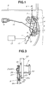
- the door locking system includes a locking mechanism 1 installed on a door “D” and capable of being locked and unlocked to lock and unlock the door “D", a lock cylinder 2 disposed adjacent an outside door handle 3 and adapted to be operated from the outside of the door “D” with a key, a locking knob or button 4 installed on a waist portion of the door “D” in such a way as to project upward therefrom and adapted to be manually operated from the inside of the door "D", and an inside door handle 5.
- the locking mechanism 1 has a locking lever 6 movable between a locking position and an unlocking position for locking and unlocking the locking mechanism 1.
- the locking lever 6 is connected via a pull rod 7 to the locking button 4 so that the locking mechanism 1 can be locked or unlocked by the operation of the locking button 4.
- the lock cylinder 2 is operated to lock or unlock the locking mechanism via a lock cylinder lever 8 and a pull rod 9, the locking lever 6 is operated toward a locking position or an unlocking position together with other locking levers (not shown) for all of other doors by means of electromagnetic actuators (not shown).
- the door locking system further includes an antitheft deadlock or security mechanism 10 which is provided to the locking mechanism 1 and includes a motor-driven actuator 11 and a rod 12 connected to the locking lever 6. By the rod 12, the locking lever 6 is locked and unlocked.
- the security mechanism 10 is adapted to be controlled by a control circuit 13 in response to a signal from a switching device which will be described in detail hereinafter.
- the security mechanism 10 locks the locking lever 6 in the locking position after the locking mechanism 1 has been locked.
- the security mechanism 10 can be operated to unlock the locking lever 6 without requiring such a troublesome operation of an unlocking switch as in a prior art system, which will be explained hereinafter in detail.
- 14 is a pull rod connecting between the outside handle 3 and the locking mechanism 1
- 15 is a pull rod connecting between the inside handle 5 and the locking mechanism 1.
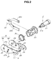
- the lock cylinder 2 includes a cylinder casing 20 fixedly attached to the door "D", and a lock cylinder proper or main body 21 rotatably encased in the cylinder casing 20.
- a switching device 22 is disposed around or adjacent the periphery of the cylinder casing 20 for detecting a locking or unlocking operation of the lock cylinder 2.
- the switching device 22 has a forked or bifurcated shape so as to straddle the cylinder casing 20 and includes an upper locking switch 22a for supplying to the control circuit 13 a locking command signal for causing the security mechanism 10 to be locked, and a lower unlocking switch 22b for supplying to the control circuit 13 an unlocking command signal for causing the security mechanism 10 to be unlocked.
- both of the locking switch 22a and the unlocking switch 22b are lead switches which are switched on or closed when coming close to and to face a magnet 23 which will be described hereinlater.
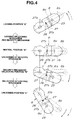
- the locking switch 22a is arranged so as to come close to and to face the magnet 23 and be closed when a switch lever 8a is rotated into a locking position "A" in Fig. 4.
- the unlocking switch 22b is arranged so as to come close to and to face the magnet 23 and be closed when the switch lever 8a is rotated into an unlocking position "B" in Fig. 4.
- a lock cylinder lever unit 8 is installed on an end portion of the lock cylinder main body 21 so as to transmit an operating force applied the lock cylinder main body 21 to the rod 9 whilst converting rotational motion of the lock cylinder main body 21 to vertical reciprocating motion of the rod 9.
- the lock cylinder lever unit 8 consists of the above mentioned switch lever 8a having at an end the magnet 23 for controlling closing and opening of the locking switch 22a and the unlocking switch 22b, and an operating force transmitting lever 8b connected at an end to the rod 9.
- the switch lever 8a has a noncircular opening 24 at an end portion.
- the lock cylinder main body 21 has a noncircular end portion 21a.
- the switch lever 8a is fitted and engaged at the noncircular opening 24 on and with the noncircular end portion 21a of the lock cylinder main body 21.
- the switch lever 8a is assembled with the lock cylinder main body 21 in such a manner as to be rotatable with the lock cylinder main body 21 toward a locking position and an unlocking position thereof.
- the operation force transmitting lever 8b has at an end thereof a circular opening 25 and is rotatably installed on the noncircular portion 21a of the lock cylinder proper 21 by inserting the noncircular end portion 21a of the lock cylinder main body 21 into the circular opening 25.
- the switch lever 8a and the operating force transmitting lever 8b are coupled with each other by inserting a guide projection 26 of the switch lever 8a into an arcuated slit 27 constituting part of a circular slit formed round the center of the opening 25, whilst a torsional spring 28 in a loaded state is interposed between the switch lever 8a and the operating force transmitting lever 8b in such a manner that the operating force transmitting lever 8b is urged toward an unlocking position "C" in Fig. 4 and that a locking side stopper end 27a of the arcuated slit 27 is usually held engaged with the guide projection 26 as seen from portions of Fig. 4 for illustrating the locking position "A" and a neutral position "N".
- the lock cylinder main body 21 is rotatable between a locking position "A” and an unlocking position “C” and further rotatable into a security mechanism unlocking position “B” between the locking position "A” and the unlocking position “C” and into a neutral position “N” between the locking position "A” and the securing mechanism unlocking position "B".
- the length of the arcuated slit 27 is determined so that when the switch lever 8a is rotated relative to the operating force transmitting lever 8b into a security mechanism unlocking position "B" and allows the magnet 23 to come close to and to face the unlocking switch 22b, the guide projection 26 is just engaged with an unlocking side stopper end 27b of the arcuated slit 27 as seen from a portion of Fig. 4 for illustrating the security mechanism unlocking position "B".
- the switch lever 8a has a pin 29 for retaining or supporting the spring 28, i.e., the spring 28 is placed around the pin 29.
- a torsional return spring 30 is disposed between the cylinder casing 20 and the switch lever 8a to return the switch lever 8a to the neutral position "N".
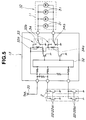
- Fig. 5 shows the control circuit 13 for the security mechanism 10.
- the control circuit 13 is adapted to control motors 31 of actuators 11 for each security mechanisms 10 provided to each doors of a 4-door vehicle.
- a signal indicative of closure of the locking switch 22a or the unlocking switch 22b of the switching device 22 is supplied therefrom to a CPU (central processing unit) 32.
- the CPU 32 is adapted to supply to the security mechanism 10 a signal for causing the security mechanism 10 to be locked when supplied with the signal indicative of closure of the locking switch 22a, and supply to the security mechanism 10 a signal for causing the security mechanism to be unlocked when supplied with the signal indicative of closure of the unlocking switch 22b.
- Each motor 31 is built in the actuator 11 of each securing mechanism 10 and causes, when for example rotated in the normal direction, the rod 12 of the actuator 11 to move forward to lock the locking lever 6 of the locking mechanism 1 in the locking position and, when rotated in the reverse direction, causes the rod 12 to move backward to unlock the locking lever 6.
- Each motor 31 is driven in the normal direction when the voltage of a battery 35 is applied via the CPU 32 to a coil 33a of a relay 33 for locking drive in response to a signal indicative of closure of the locking switch 22a and a contact 33b is thrown into a closed position to form a closed loop.
- each motor 31 is driven in the reverse direction when the voltage of the battery 35 is applied via the CPU 32 to a coil 34a of a relay 34 for unlocking drive in response to a signal indicative of closure of the unlocking switch 22b and a contact 34b is thrown into a closed position to form a closed loop.
- an operation of the lock cylinder 2 in the direction to lock the locking mechanism 1 causes the switch lever 8a and the operating force transmitting lever 8b to rotate as one body due to engagement of the guide projection 26 and the locking side stopper end 27a of the arcuated slit 27.
- the operating force transmitting lever 8b When the operating force transmitting lever 8b is rotated into the locking position "A" together with the switch lever 8a, it operates the locking mechanism by way of the pull rod 9 and causes the same to be locked.
- the switch lever 8a can be rotated with a small operating force since no operation force for operating the locking mechanism 1 is needed.
- control circuit 13 supplies to the securing mechanism 10 a signal for causing the security mechanism 10 to be unlocked.
- the actuator 11 is thus actuated to drive the rod 12 in such a manner that the rod 12 unlocks the locking button 6 for thereby unlocking the security mechanism 10, i.e., releasing the locking mechanism 1 from the deadlock condition prior to unlocking of the locking mechanism 1.
- actuator of the security mechanism has been described as being of a motor-driven type, i.e., an electrically operated type, it can otherwise be of an electromagnetically operated type.
Landscapes
- Lock And Its Accessories (AREA)
Applications Claiming Priority (2)
| Application Number | Priority Date | Filing Date | Title |
|---|---|---|---|
| JP17348693A JPH0726816A (ja) | 1993-07-14 | 1993-07-14 | ドアロック装置 |
| JP173486/93 | 1993-07-14 |
Publications (3)
| Publication Number | Publication Date |
|---|---|
| EP0634548A2 true EP0634548A2 (de) | 1995-01-18 |
| EP0634548A3 EP0634548A3 (de) | 1995-07-19 |
| EP0634548B1 EP0634548B1 (de) | 1998-03-04 |
Family
ID=15961402
Family Applications (1)
| Application Number | Title | Priority Date | Filing Date |
|---|---|---|---|
| EP94110919A Expired - Lifetime EP0634548B1 (de) | 1993-07-14 | 1994-07-13 | Verriegelungssystem für Fahrzeugtüren |
Country Status (4)
| Country | Link |
|---|---|
| US (1) | US5566562A (de) |
| EP (1) | EP0634548B1 (de) |
| JP (1) | JPH0726816A (de) |
| DE (1) | DE69408742T2 (de) |
Cited By (4)
| Publication number | Priority date | Publication date | Assignee | Title |
|---|---|---|---|---|
| GB2320051A (en) * | 1996-12-03 | 1998-06-10 | Bosch Gmbh Robert | Actuating device for a locking system |
| EP0879930A1 (de) * | 1997-05-21 | 1998-11-25 | Meritor Light Vehicle Systems (UK) Ltd | Türmechanismus |
| FR2798693A1 (fr) | 1999-09-16 | 2001-03-23 | Renault | Dispositif de verrouillage a grande course pour des portes d'un vehicule automobile |
| EP2657438A4 (de) * | 2010-12-22 | 2017-06-21 | Kabushiki Kaisha Honda Lock | Betriebsvorrichtung mit zentralisierter entriegelung |
Families Citing this family (12)
| Publication number | Priority date | Publication date | Assignee | Title |
|---|---|---|---|---|
| DE19628878A1 (de) * | 1996-05-23 | 1998-02-12 | Bayerische Motoren Werke Ag | Steuerungsverfahren für eine Brennkraftmaschine |
| BR9710112A (pt) * | 1996-07-04 | 1999-08-10 | Huf Huelsbeck & Fuerst Gmbh | Fecho para portas capôs tampas ou semelhantes especialmente de veículos como veículos automotores |
| FR2752005B1 (fr) * | 1996-07-30 | 2004-11-26 | Kiekert Ag | Fermeture de portiere de vehicule automobile avec systeme de serrure et systeme de fermeture |
| GB2316436B (en) * | 1996-08-24 | 2001-03-07 | Kiekert Ag | Motor vehicle door lock |
| DE29618688U1 (de) * | 1996-10-26 | 1997-01-02 | Kiekert AG, 42579 Heiligenhaus | Einrichtung zum Abfragen von Schaltstellungen an einem Kraftfahrzeugtürverschluß |
| DE19646810C2 (de) * | 1996-11-13 | 1999-02-04 | Kiekert Ag | Kraftfahrzeugtürverschluß mit Schloßsystem, Schließsystem und auf eine Auswerteelektronik arbeitender Einrichtung Abfrage der Funktionsstellungen des Schließzylinders, die mit Hallsensor-Chips arbeitet |
| DE19942870B4 (de) * | 1999-09-08 | 2007-09-06 | Volkswagen Ag | Zentralverriegelungsvorrichtung eines Kraftfahrzeugs mit einer Handschuhfach-Verriegelung |
| US20040011097A1 (en) * | 2002-07-18 | 2004-01-22 | Jeffers Edward S. | Electromechanical keyless entry system for storage devices |
| US20070163313A1 (en) * | 2006-01-18 | 2007-07-19 | Zamora Oscar A | Vehicle Lock |
| DE202010015399U1 (de) * | 2010-11-12 | 2012-02-13 | Kiekert Ag | Kraftfahrzeugtürverschluss |
| DE102014114512A1 (de) * | 2014-10-07 | 2016-04-07 | Kiekert Aktiengesellschaft | Kraftfahrzeugtürverschluss |
| CA2878539A1 (en) * | 2015-01-19 | 2016-07-19 | T2 Systems Canada Inc. | Dual cam lock apparatus |
Citations (1)
| Publication number | Priority date | Publication date | Assignee | Title |
|---|---|---|---|---|
| GB2034802A (en) * | 1978-11-02 | 1980-06-11 | Fichtel & Sachs Ag | Locking system for vehicle doors and the like |
Family Cites Families (8)
| Publication number | Priority date | Publication date | Assignee | Title |
|---|---|---|---|---|
| US2339170A (en) * | 1941-06-27 | 1944-01-11 | Gustave E Berliner | Automobile door lock control device |
| IT1131405B (it) * | 1979-03-24 | 1986-06-25 | Kiekert Soehne Arn | Dispositivo di chiusura a comando centralizzato per porte di veicoli a motore |
| US4563885A (en) * | 1982-04-08 | 1986-01-14 | Excalibur Locks, Inc. | Patio sliding door lock assembly and method |
| JPH07116876B2 (ja) * | 1985-12-18 | 1995-12-18 | 有限会社同栄企画センター | 自動車扉の施解錠方法および施解錠装置 |
| US4904006A (en) * | 1986-10-06 | 1990-02-27 | Aisin Seiki Kabushiki Kaisha | Door lock assembly for automotive vehicles |
| JPS6432947A (en) * | 1987-07-30 | 1989-02-02 | Shiroki Corp | Door lock/unlock detecting device for burglary preventing device for automobile |
| GB2262769B (en) * | 1991-12-24 | 1994-09-21 | Ohi Seisakusho Co Ltd | Antitheft type power door lock system |
| US5428978A (en) * | 1994-03-29 | 1995-07-04 | Alpha Corporation | Cylinder lock device resistible against unauthorized unlocking |
-
1993
- 1993-07-14 JP JP17348693A patent/JPH0726816A/ja active Pending
-
1994
- 1994-07-13 EP EP94110919A patent/EP0634548B1/de not_active Expired - Lifetime
- 1994-07-13 US US08/274,261 patent/US5566562A/en not_active Expired - Fee Related
- 1994-07-13 DE DE69408742T patent/DE69408742T2/de not_active Expired - Fee Related
Patent Citations (1)
| Publication number | Priority date | Publication date | Assignee | Title |
|---|---|---|---|---|
| GB2034802A (en) * | 1978-11-02 | 1980-06-11 | Fichtel & Sachs Ag | Locking system for vehicle doors and the like |
Cited By (8)
| Publication number | Priority date | Publication date | Assignee | Title |
|---|---|---|---|---|
| GB2320051A (en) * | 1996-12-03 | 1998-06-10 | Bosch Gmbh Robert | Actuating device for a locking system |
| GB2320051B (en) * | 1996-12-03 | 1998-10-07 | Bosch Gmbh Robert | Motor vehicle locking mechanism |
| DE19650136B4 (de) * | 1996-12-03 | 2006-06-29 | Brose Schließsysteme GmbH & Co.KG | Kraftfahrzeug-Türschloß o. dgl. mit Freilauf |
| EP0879930A1 (de) * | 1997-05-21 | 1998-11-25 | Meritor Light Vehicle Systems (UK) Ltd | Türmechanismus |
| WO1998053168A1 (en) * | 1997-05-21 | 1998-11-26 | Meritor Light Vehicle Systems (Uk) Limited | Door mechanism |
| US6431617B1 (en) | 1997-05-21 | 2002-08-13 | Meritor Light Vehicle Systems (Uk) Ltd. | Door mechanism |
| FR2798693A1 (fr) | 1999-09-16 | 2001-03-23 | Renault | Dispositif de verrouillage a grande course pour des portes d'un vehicule automobile |
| EP2657438A4 (de) * | 2010-12-22 | 2017-06-21 | Kabushiki Kaisha Honda Lock | Betriebsvorrichtung mit zentralisierter entriegelung |
Also Published As
| Publication number | Publication date |
|---|---|
| DE69408742T2 (de) | 1998-06-25 |
| DE69408742D1 (de) | 1998-04-09 |
| US5566562A (en) | 1996-10-22 |
| EP0634548B1 (de) | 1998-03-04 |
| EP0634548A3 (de) | 1995-07-19 |
| JPH0726816A (ja) | 1995-01-27 |
Similar Documents
| Publication | Publication Date | Title |
|---|---|---|
| EP0634548B1 (de) | Verriegelungssystem für Fahrzeugtüren | |
| US6116664A (en) | Lock, in particular for car doors or the like | |
| EP0738363B2 (de) | Betätigungsvorrichtung für kraftfahrzeugtürschlösser | |
| EP0775791B1 (de) | Fahrzeugstürstelltrieb | |
| CA2039072C (en) | Low effort remote latch actuator | |
| US6099048A (en) | Automotive door latching system | |
| US4702095A (en) | Electro-mechanical locking device | |
| US4843849A (en) | Door lock mechanism for a motor vehicle | |
| EP0775793B1 (de) | Fahrzeugstürstellantrieb | |
| US6286878B1 (en) | Electrically locked motor vehicle door lock | |
| KR100373242B1 (ko) | 슬라이딩 도어의 록킹콘트롤러 | |
| US6655179B2 (en) | Automotive door lock assembly | |
| US6045168A (en) | Door latch with improved double lock | |
| GB2400404A (en) | Selective one-motion door opening mechanism for door latch of vehicle | |
| CA1271044A (en) | Door lock device for automobile | |
| JP2832235B2 (ja) | トランク用扉のロック装置 | |
| EP1245764B1 (de) | Betätigungsvorrichtung eines Fahrzeugtürschlosses | |
| KR20200141639A (ko) | 테일 게이트와 트렁크에 적용되는 래치 | |
| JP2004124687A (ja) | ドアロック装置 | |
| JP4169428B2 (ja) | 車両における扉体の開閉操作装置 | |
| EP0829602B1 (de) | Kraftfahrzeug-Türschloss | |
| EP0117560A2 (de) | Türschlosssystem | |
| KR100372459B1 (ko) | 차량의 도어잠금장치 | |
| KR0178503B1 (ko) | 자동차 도어의 록킹장치 | |
| JPS63219776A (ja) | 車両用ドアロツク機構 |
Legal Events
| Date | Code | Title | Description |
|---|---|---|---|
| PUAI | Public reference made under article 153(3) epc to a published international application that has entered the european phase |
Free format text: ORIGINAL CODE: 0009012 |
|
| 17P | Request for examination filed |
Effective date: 19940713 |
|
| AK | Designated contracting states |
Kind code of ref document: A2 Designated state(s): DE FR GB |
|
| PUAL | Search report despatched |
Free format text: ORIGINAL CODE: 0009013 |
|
| RHK1 | Main classification (correction) |
Ipc: E05B 47/00 |
|
| AK | Designated contracting states |
Kind code of ref document: A3 Designated state(s): DE FR GB |
|
| GRAG | Despatch of communication of intention to grant |
Free format text: ORIGINAL CODE: EPIDOS AGRA |
|
| 17Q | First examination report despatched |
Effective date: 19970514 |
|
| GRAG | Despatch of communication of intention to grant |
Free format text: ORIGINAL CODE: EPIDOS AGRA |
|
| GRAH | Despatch of communication of intention to grant a patent |
Free format text: ORIGINAL CODE: EPIDOS IGRA |
|
| GRAH | Despatch of communication of intention to grant a patent |
Free format text: ORIGINAL CODE: EPIDOS IGRA |
|
| GRAA | (expected) grant |
Free format text: ORIGINAL CODE: 0009210 |
|
| AK | Designated contracting states |
Kind code of ref document: B1 Designated state(s): DE FR GB |
|
| REF | Corresponds to: |
Ref document number: 69408742 Country of ref document: DE Date of ref document: 19980409 |
|
| ET | Fr: translation filed | ||
| PLBE | No opposition filed within time limit |
Free format text: ORIGINAL CODE: 0009261 |
|
| STAA | Information on the status of an ep patent application or granted ep patent |
Free format text: STATUS: NO OPPOSITION FILED WITHIN TIME LIMIT |
|
| 26N | No opposition filed | ||
| PGFP | Annual fee paid to national office [announced via postgrant information from national office to epo] |
Ref country code: GB Payment date: 19990707 Year of fee payment: 6 |
|
| PGFP | Annual fee paid to national office [announced via postgrant information from national office to epo] |
Ref country code: FR Payment date: 19990709 Year of fee payment: 6 |
|
| PGFP | Annual fee paid to national office [announced via postgrant information from national office to epo] |
Ref country code: DE Payment date: 19990716 Year of fee payment: 6 |
|
| PG25 | Lapsed in a contracting state [announced via postgrant information from national office to epo] |
Ref country code: GB Free format text: LAPSE BECAUSE OF NON-PAYMENT OF DUE FEES Effective date: 20000713 |
|
| GBPC | Gb: european patent ceased through non-payment of renewal fee |
Effective date: 20000713 |
|
| PG25 | Lapsed in a contracting state [announced via postgrant information from national office to epo] |
Ref country code: FR Free format text: LAPSE BECAUSE OF NON-PAYMENT OF DUE FEES Effective date: 20010330 |
|
| REG | Reference to a national code |
Ref country code: FR Ref legal event code: ST |
|
| PG25 | Lapsed in a contracting state [announced via postgrant information from national office to epo] |
Ref country code: DE Free format text: LAPSE BECAUSE OF NON-PAYMENT OF DUE FEES Effective date: 20010501 |