EP0634364B1 - Pure water manufacturing method - Google Patents
Pure water manufacturing method Download PDFInfo
- Publication number
- EP0634364B1 EP0634364B1 EP94905834A EP94905834A EP0634364B1 EP 0634364 B1 EP0634364 B1 EP 0634364B1 EP 94905834 A EP94905834 A EP 94905834A EP 94905834 A EP94905834 A EP 94905834A EP 0634364 B1 EP0634364 B1 EP 0634364B1
- Authority
- EP
- European Patent Office
- Prior art keywords
- water
- raw water
- toc
- pure water
- tower
- Prior art date
- Legal status (The legal status is an assumption and is not a legal conclusion. Google has not performed a legal analysis and makes no representation as to the accuracy of the status listed.)
- Expired - Lifetime
Links
Images


Classifications
-
- C—CHEMISTRY; METALLURGY
- C02—TREATMENT OF WATER, WASTE WATER, SEWAGE, OR SLUDGE
- C02F—TREATMENT OF WATER, WASTE WATER, SEWAGE, OR SLUDGE
- C02F9/00—Multistage treatment of water, waste water or sewage
-
- B—PERFORMING OPERATIONS; TRANSPORTING
- B01—PHYSICAL OR CHEMICAL PROCESSES OR APPARATUS IN GENERAL
- B01J—CHEMICAL OR PHYSICAL PROCESSES, e.g. CATALYSIS OR COLLOID CHEMISTRY; THEIR RELEVANT APPARATUS
- B01J41/00—Anion exchange; Use of material as anion exchangers; Treatment of material for improving the anion exchange properties
- B01J41/04—Processes using organic exchangers
- B01J41/07—Processes using organic exchangers in the weakly basic form
-
- C—CHEMISTRY; METALLURGY
- C02—TREATMENT OF WATER, WASTE WATER, SEWAGE, OR SLUDGE
- C02F—TREATMENT OF WATER, WASTE WATER, SEWAGE, OR SLUDGE
- C02F1/00—Treatment of water, waste water, or sewage
- C02F1/02—Treatment of water, waste water, or sewage by heating
-
- C—CHEMISTRY; METALLURGY
- C02—TREATMENT OF WATER, WASTE WATER, SEWAGE, OR SLUDGE
- C02F—TREATMENT OF WATER, WASTE WATER, SEWAGE, OR SLUDGE
- C02F1/00—Treatment of water, waste water, or sewage
- C02F1/02—Treatment of water, waste water, or sewage by heating
- C02F1/025—Thermal hydrolysis
-
- C—CHEMISTRY; METALLURGY
- C02—TREATMENT OF WATER, WASTE WATER, SEWAGE, OR SLUDGE
- C02F—TREATMENT OF WATER, WASTE WATER, SEWAGE, OR SLUDGE
- C02F1/00—Treatment of water, waste water, or sewage
- C02F1/20—Treatment of water, waste water, or sewage by degassing, i.e. liberation of dissolved gases
-
- C—CHEMISTRY; METALLURGY
- C02—TREATMENT OF WATER, WASTE WATER, SEWAGE, OR SLUDGE
- C02F—TREATMENT OF WATER, WASTE WATER, SEWAGE, OR SLUDGE
- C02F1/00—Treatment of water, waste water, or sewage
- C02F1/30—Treatment of water, waste water, or sewage by irradiation
- C02F1/32—Treatment of water, waste water, or sewage by irradiation with ultraviolet light
-
- C—CHEMISTRY; METALLURGY
- C02—TREATMENT OF WATER, WASTE WATER, SEWAGE, OR SLUDGE
- C02F—TREATMENT OF WATER, WASTE WATER, SEWAGE, OR SLUDGE
- C02F1/00—Treatment of water, waste water, or sewage
- C02F1/42—Treatment of water, waste water, or sewage by ion-exchange
-
- C—CHEMISTRY; METALLURGY
- C02—TREATMENT OF WATER, WASTE WATER, SEWAGE, OR SLUDGE
- C02F—TREATMENT OF WATER, WASTE WATER, SEWAGE, OR SLUDGE
- C02F1/00—Treatment of water, waste water, or sewage
- C02F1/44—Treatment of water, waste water, or sewage by dialysis, osmosis or reverse osmosis
- C02F1/441—Treatment of water, waste water, or sewage by dialysis, osmosis or reverse osmosis by reverse osmosis
-
- C—CHEMISTRY; METALLURGY
- C02—TREATMENT OF WATER, WASTE WATER, SEWAGE, OR SLUDGE
- C02F—TREATMENT OF WATER, WASTE WATER, SEWAGE, OR SLUDGE
- C02F1/00—Treatment of water, waste water, or sewage
- C02F1/44—Treatment of water, waste water, or sewage by dialysis, osmosis or reverse osmosis
- C02F1/444—Treatment of water, waste water, or sewage by dialysis, osmosis or reverse osmosis by ultrafiltration or microfiltration
-
- C—CHEMISTRY; METALLURGY
- C02—TREATMENT OF WATER, WASTE WATER, SEWAGE, OR SLUDGE
- C02F—TREATMENT OF WATER, WASTE WATER, SEWAGE, OR SLUDGE
- C02F1/00—Treatment of water, waste water, or sewage
- C02F1/52—Treatment of water, waste water, or sewage by flocculation or precipitation of suspended impurities
-
- C—CHEMISTRY; METALLURGY
- C02—TREATMENT OF WATER, WASTE WATER, SEWAGE, OR SLUDGE
- C02F—TREATMENT OF WATER, WASTE WATER, SEWAGE, OR SLUDGE
- C02F1/00—Treatment of water, waste water, or sewage
- C02F1/66—Treatment of water, waste water, or sewage by neutralisation; pH adjustment
-
- C—CHEMISTRY; METALLURGY
- C02—TREATMENT OF WATER, WASTE WATER, SEWAGE, OR SLUDGE
- C02F—TREATMENT OF WATER, WASTE WATER, SEWAGE, OR SLUDGE
- C02F1/00—Treatment of water, waste water, or sewage
- C02F1/72—Treatment of water, waste water, or sewage by oxidation
- C02F1/722—Oxidation by peroxides
-
- C—CHEMISTRY; METALLURGY
- C02—TREATMENT OF WATER, WASTE WATER, SEWAGE, OR SLUDGE
- C02F—TREATMENT OF WATER, WASTE WATER, SEWAGE, OR SLUDGE
- C02F1/00—Treatment of water, waste water, or sewage
- C02F1/72—Treatment of water, waste water, or sewage by oxidation
- C02F1/725—Treatment of water, waste water, or sewage by oxidation by catalytic oxidation
-
- C—CHEMISTRY; METALLURGY
- C02—TREATMENT OF WATER, WASTE WATER, SEWAGE, OR SLUDGE
- C02F—TREATMENT OF WATER, WASTE WATER, SEWAGE, OR SLUDGE
- C02F2101/00—Nature of the contaminant
- C02F2101/10—Inorganic compounds
- C02F2101/12—Halogens or halogen-containing compounds
- C02F2101/14—Fluorine or fluorine-containing compounds
-
- C—CHEMISTRY; METALLURGY
- C02—TREATMENT OF WATER, WASTE WATER, SEWAGE, OR SLUDGE
- C02F—TREATMENT OF WATER, WASTE WATER, SEWAGE, OR SLUDGE
- C02F2101/00—Nature of the contaminant
- C02F2101/10—Inorganic compounds
- C02F2101/16—Nitrogen compounds, e.g. ammonia
-
- C—CHEMISTRY; METALLURGY
- C02—TREATMENT OF WATER, WASTE WATER, SEWAGE, OR SLUDGE
- C02F—TREATMENT OF WATER, WASTE WATER, SEWAGE, OR SLUDGE
- C02F2103/00—Nature of the water, waste water, sewage or sludge to be treated
- C02F2103/02—Non-contaminated water, e.g. for industrial water supply
- C02F2103/04—Non-contaminated water, e.g. for industrial water supply for obtaining ultra-pure water
-
- C—CHEMISTRY; METALLURGY
- C02—TREATMENT OF WATER, WASTE WATER, SEWAGE, OR SLUDGE
- C02F—TREATMENT OF WATER, WASTE WATER, SEWAGE, OR SLUDGE
- C02F2103/00—Nature of the water, waste water, sewage or sludge to be treated
- C02F2103/12—Nature of the water, waste water, sewage or sludge to be treated from the silicate or ceramic industries, e.g. waste waters from cement or glass factories
-
- Y—GENERAL TAGGING OF NEW TECHNOLOGICAL DEVELOPMENTS; GENERAL TAGGING OF CROSS-SECTIONAL TECHNOLOGIES SPANNING OVER SEVERAL SECTIONS OF THE IPC; TECHNICAL SUBJECTS COVERED BY FORMER USPC CROSS-REFERENCE ART COLLECTIONS [XRACs] AND DIGESTS
- Y10—TECHNICAL SUBJECTS COVERED BY FORMER USPC
- Y10S—TECHNICAL SUBJECTS COVERED BY FORMER USPC CROSS-REFERENCE ART COLLECTIONS [XRACs] AND DIGESTS
- Y10S210/00—Liquid purification or separation
- Y10S210/90—Ultra pure water, e.g. conductivity water
-
- Y—GENERAL TAGGING OF NEW TECHNOLOGICAL DEVELOPMENTS; GENERAL TAGGING OF CROSS-SECTIONAL TECHNOLOGIES SPANNING OVER SEVERAL SECTIONS OF THE IPC; TECHNICAL SUBJECTS COVERED BY FORMER USPC CROSS-REFERENCE ART COLLECTIONS [XRACs] AND DIGESTS
- Y10—TECHNICAL SUBJECTS COVERED BY FORMER USPC
- Y10S—TECHNICAL SUBJECTS COVERED BY FORMER USPC CROSS-REFERENCE ART COLLECTIONS [XRACs] AND DIGESTS
- Y10S210/00—Liquid purification or separation
- Y10S210/902—Materials removed
- Y10S210/915—Fluorine containing
Definitions
- the present invention relates to a method of producing pure water (deionized water including ultrapure water) and, more particuraly, to a method of producing ultrapure water which can greatly reduce TOC (total organic carbon) in the pure water than a conventional method.
- a conventional water purifying apparatus for producing ultrapure water from raw water such as city water, well water and industrial water is composed of a pretreatment equipment, a primary pure water equipment and secondary pure water equipment.
- the pretreatment equipment is composed of coagulation, floatation and filtration units.
- the primary pure water equipment is composed of two reverse osmosis membrane units and a mixed bed ion exchange unit, or a demineralization equipment and a reverse osmosis membrane unit.
- the secondary pure water equipment is composed of a low pressure mercury ultraviolet oxidization unit, a demineralization equipment and an ultrafilter (ultrafiltration membrane separation device).
- the above deminerlization equipment comprises an anion exchange column, a mixed bed ion exchange column or an anion exchange column and a mixed bed ion exchange column which are arranged in series.
- the reverse osmosis membrane units, the demineralization equipment and the low pressure mercury ultraviolet oxidization unit reduce the TOC components in raw water by separation, adsorption, decomposition or the like.
- TOC reducing mechanisms of these units or equipmemts are as follows.
- Reverse osmosis membrane unit Raw water is filtered through a reverse osmosis membrane so as to remove ionic and colloidal TOC.
- Low pressure mercury oxidization unit TOC is decomposed into an organic acid and further into CO 2 by ultraviolet of 185 nm projected from a low pressure mercury ultraviolet lamp.
- the organic acid produced is removed by an ion exchange resin provided at a subsequent stage. This mechanism is used especially for the decomposition of a volatile organic master.
- the ultrapure water produced by the above-described conventional pure water apparatus still contains about 3 to 5 ppb of TOC.
- the ultrapure water may be treated by a multiplicity of stages of reverse osmosis membrane units and an increase in irradiation of a low pressure mercury ultraviolet unit be considered. It has been confirmed, however, as a result of the studies undertaken by the inventors that neither can further reduce the TOC in ultrapure water because of the following reasons.
- Raw water contains a urea component as one of the TOC components. Since the urea component is nonionic, the urea component is impossible to be removed by ion exchange. The urea component is removed at a low rate by a reverse osmosis membrane separation.
- the urea component removal rate by a high salt rejection type reverse osmosis membrane unit which is generally used as one of the two reverse osmosis membrane units in a primary pure water purifying equipment is about 60%.
- urea cannot be decomposed by a low pressure mercury ultraviolet oxidization unit.
- Raw water contains not a little amount of urea, which obstructs the reduction of the TOC in ultrapure water. Since it is difficult to remove urea by a conventional water purifying apparatus, there is a limitation to the reduction of TOC.
- the city water of Atsugi City, Kanagawa, Japan contains about 30 ppb of urea.
- Even after treatment of the city water by the above-mentioned process (ii) which uses two reverse osmosis membrane units as the primary pure water equipment about 8 ppb of urea is detected in the ultrapure water obtained by a conventional ultra water apparatus. 8 ppb of urea will come to about 1.5 ppb as calculated in terms of TOC. It is about 50% of the TOC components in ultrapure water which contains 3 ppb of TOC.
- Waste water from a semiconductor rinsing system is treated so as to produce ultrapure water and be used again as semiconductor rinse water.
- the present inventor carried out the experiments of adding sulfuric acid and an oxidizing agent to urea-containing water and decomposing urea by heat treatment.
- the pH after adding the acid and the type and amount of oxidizing agent are as follows:
- the urea concentration after heating the water is shown in FIG. 9.
- FIG.9 shows the following matter.
- the heat decoposition deficiency is increased, which is apparent from comparison between Nos. 1,3 havingthe pH of 5.5 and Nos. 2,4 having the pH of 4.5.
- the heat decomposition efficiency is increased as the temperature becomes higher.
- the method of producing pure water from raw water containing hydrofluoric acid and TOC components according to the present invention has been invented on the basis of these experiments and various other experiments, and comprises:
- persulfates e.g., Na 2 S 2 O 8 , K 2 S 2 O 8
- oxygen peroxide e.g., oxygen peroxide
- persulfates such as Na 2 S 2 O 8 and K 2 S 2 O 8 are preferable.
- the temperature for thermal decomposition is preferably not lower than 110°C, more preferably 120 to 170°C and the time for decomposition is preferably 2 to 5 minutes.
- An oxidizing catalyst may be used during heating, but in the case of not using a catalyst, the water is preferably held at 130 to 150°C.
- platinum held by a carrier is preferable.
- the method of present invention it is possible to decompose urea in the raw water with easiness and with efficiency, and to effectively remove the ions by deionization which are produced by decomposition.
- FIG. 1 is a flowchart of an embodiment of a method of producing primary pure water according to the present invention.
- the method shown in FIG.1 has an improvement in the before-described process (ii) in the related art.
- a thermal decomposition process is inserted between the cation exchange tower and the vacuum gas tower in the two-bed three-tower type ion exchange equipment in the process (ii).
- Raw water is first introduced to a coaguration, floatation and filtration units 1 through a pipe 11 and treated, and after the water is introduced to a cation exchange tower 2 through a pipe 12 for the purpose of cation exchange, the water is supplied to an acidic softened water tank 3 through a pipe 13 and stored therein.
- the pH of the acidic softened water obtained is 3.0.
- an oxidizing agent is added to the water through a pipe 14A.
- the water is heat-exchanged with the treated water of a later-described reaction vessel 6 by the heat exchanger 4, and further heated by a heater 5 provided with a boiler 5A.
- the water is then introduced to the reaction vessel 6 through a pipe 15.
- urea and other TOC components contained in the water are efficiently decomposed by catalytic heat treatment.
- the effluent from the reaction vessel 6 is introduced to the heat exchanger 4 through a pipe 16 and after it is heat-exchanged and cooled, it is introduced to a reverse osmosis membrane unit 9c through a decarbonation tower 7, a pipe 17, an anion exchange tower 8 and a pipe 18, so that primary pure water is produced.
- the primary pure water is supplied to a secondary pure water producing equipment so that almost all of the ions and other components produced by the decomposition are removed.
- the thermal decomposition of urea and the like is executed in the presence of an oxidizing agent in the water having the pH of not more than 4.5. If the pH is more than 4.5, the decomposition efficiency is lowered. However, if the pH is too low, the load of the post-treatment increases, so that the pH of the water is preferably about 2 to 3 in an ordinary case.
- oxidizing agent persulfates such as hydrogen peroxide (H 2 O 2 ) and peroxy potassium disulfide (K 2 S 2 O 8 ) and the like are usable.
- the dosage of oxidizing agent such as H 2 O 2 differs depending upon the TOC of the raw water and the thermal decomposition temperature, but about 10 to 20 mg/l per 1 mg/l of TOC of the raw water is preferable.
- a persulfate is preferably used as an oxidizing agent.
- the dosage of persulfate is preferably about 70 mg/l per 1 mg/l of TOC of the raw water.
- the thermal decomposition temperature is made higher, the decompositon efficiency becomes higher and the dosage of oxidizing agent is reduced. From the view point of operation, however, the thermal decomposition temperature is preferably 120 to 170°C, more preferably 130 to 150°C.
- the thermal decomposition is preferably catalytic decomposition using a catalyst.
- a platinum catalyst such as platinum held by a carrier and a platinum-plated catalyst is preferable.
- the method shown in FIG.1 has the thermal decomposition process applied to the process (ii) in the related art. It is also possible to apply the present invention to the process (i) in the related art.
- the thermal decomposition process is inserted before two-stage reverse osmosis process, so that an acid such as sulfuric acid is added to the water treated by the coagulation , floatation and filtration units so as to adjust the pH to not more than 4.5 and the treated water is heated in the presence of an oxidizing agent, and then, the heated water is decomposed by catalytic heat treatment.
- the effluent is heat-recovered and cooled to an ordinary temperature, and thereafter the water is supplied to the two-stage reverse osmosis membrane process.
- the thermal decomposition treatment is preferably executed in the primary pure water producing equipment.
- FIG. 2 is a flowchart of another embodiment of the present invention.
- a reducing agent such as NaHSO 4 is added to raw water such as city water so as to remove the remaining chlorine, and treatment by cation exchange tower 2 is executed.
- an oxidizing agent such as H 2 O 2 is added to the water, it is heated by the heat exchanger 4 and the heater 5, and introduced to the reaction vessel 6.
- the TOC components are decomposed by the reaction vessel 6.
- the water from the reaction vessel 6 is serially treated by the anion exchange tower 8, the decarbonation tower 7, a cation exchange tower 9a, an anion exchange tower 9b, a reverse osmosis membrane unit 9c, a low pressure mercury ultraviolet oxidization unit 9d for decomposition of an organic matter, a nonregeneration type ion exchanger (mixed bed ion exchange resin column) 9e for removing ions of the organic matter produced by decomposition, and an ultrafiltration membrane separation device 9f for separating the fine particles of the ion exchange resin which flow out of the ion exchanger 9e.
- a nonregeneration type ion exchanger mixed bed ion exchange resin column
- ultrafiltration membrane separation device 9f for separating the fine particles of the ion exchange resin which flow out of the ion exchanger 9e.
- Example 1 shows an example of the operation of the apparatus shown in FIG. 2.
- the city water of Atsugi city was treated by the following process while using the apparatus shown in FIG. 2.
- the TOC of the ultrapure water obtained is shown in Table 1.
- the city water (TOC: 590 ppb) of Atsugi city was treated by the following process.
- the TOC of the ultrapure water obtained is shown in Table 1.
- FIG. 3 is a flowchart of a primary pure water producing system for treating waste semiconductor rinse water so as to be used again as semiconductor rinse water.
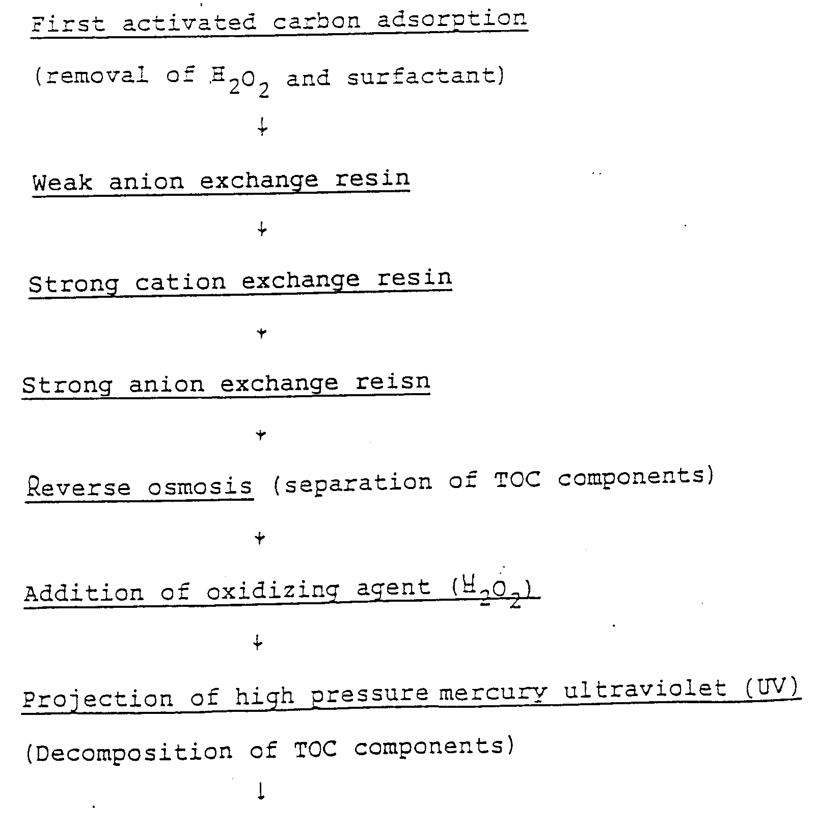
- H 2 O 2 and a surfactant are removed from waste semiconductor rinse water by an activated carbon adsorption column 21
- hydrofluoric acid, hydrochloric acid, nitric acid, sulfuric acid, etc. are removed by a weak anion exchange tower 22.
- Na 2 S 2 O 8 and H 2 SO 4 are added to the water, it is heated by a first heat exchanger 23 and a second heat exchanger 24, and left in a reaction vessel 29 (without a catalyst) for 2 to 5 minutes.
- the second heat exchanger 24 has a steam heater 24a as a heating source, while the first heat exchanger 23 has a hot water heater 23a as a heating source through which the hot treated water taken out of the second heat exchanger 24 is passed.
- the hot treated water taken out of the second heat exchanger 24 is passed through the hot water heater 23a and then introduced to a tank 25, a weak anion exchange tower 26, a strong cation exchange tower 27 and a strong anion exchange tower 28 so as to remove anions and cations.
- Na 2 SO 4 , H 2 SO 4 , CO 2 , unreacted Na 2 S 2 O 8 , etc. are removed. It is possible that the weak anion exchange tower 26 is omitted and the water from the tank 25 is directly introduced to the strong cation exchange tower 27.
- the system shown in FIG. 3 has the following advantages.
- bacteria can be completely killed by heating the water to a temperature of not lower than 120°C by the second heat exchanger 14.
- Example 2 and Examples 3 to 6 show examples of the operation of the apparatus system shown in FIG. 3.
- Waste semiconductor rinse water was treated in the same way as in Example 2 except that the temperature of the treated water in the second heat exchanger 24 was changed to 110°C, 130°C, 140°C or 150°C, respectively.
- the TOC concentrations of the treated water are shown in Table 2.
- FIG. 4 is a flowchart of the same system as that shown in FIG. 3 except that the activated carbon column and the first weak anion exchange tower 22 were omitted.
- the weak anion exchange tower 26 is provided in order to enhance the regeneration efficiency by a regenerant (NaOH) in the ion exchange tower, but it may be omitted.
- a reverse osmosis membrane unit may be used in place of the ion exchange tower 26, 27 and 28.
- the system shown in FIG. 4 has the following advantages.
- Example 7 shows an example of the operation of the system shown in FIG. 4.
- the specification of each equipment used in the operation is the same as that in Example 2.
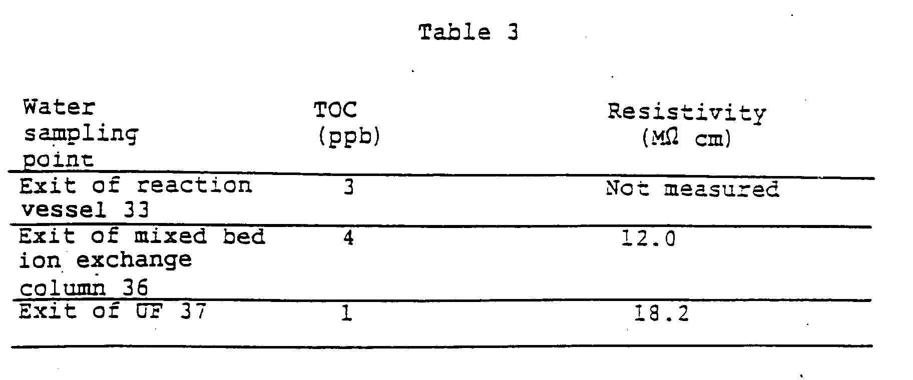
- the treated water having a TOC concentration of 2 ppb and a resistivity of 13 M ⁇ cm was obtained.
- the TOC concentration of the water introduced from the reaction vessel 29 to the tank 25 was 3 ppb.
- FIG. 5 is a flowchart of a system for producing water having a low TOC concentration by treating mixed water of city water and waste semiconductor rinse water.
- An oxidizing agent (persulfate) is added to the mixed water, and after the mixed water is heated by a first heat exchanger 31 and a second heat exchanger 32, it is passed through a reaction vessel 33 having no catalyst.
- the second heat exchanger 32 has a steam heater 32a as a heating source, while the first heat exchanger 31 has a hot water heater 31a as a heating source through which the hot treated water taken out of the reaction vessel 33 is passed.
- FIG. 6 shows a system for producing ultrapure water by further purifying the water treated by the apparatus shown in FIG. 5.
- the treated water taken out of a reaction vessel 33 is heat-exchanged by the heater 31a of the first heat exchanger 31 so as to be cooled approximately to an ordinary temperature.
- the treated water is supplied to a reverse osmosis membrane unit (RO) 34a and demineralization equipment 34b to obtain primary pure water, which is stored in a tank 34c.
- the primary pure water is then introduced to a low-pressure mercury ultraviolet oxidization unit (UV) 35, a mixed bed ion exchange column 36 and an ultrafiltration membrane device (UF) 37, thereby producing ultrapure water.
- the demineralization equipment 34b is preferably a mixed bed ion exchange tower or a two-column system (a strong cation exchange tower and a strong anion exchange tower arranged in series).
- a nonregeneration-type ion exchanger is preferable.
- Example 8 shows an example of the operation of the system shown in FIG. 6.
- the specification of each equipment used in the operation is as follows.
- Reverse osmosis membrane unit 34a Reverse osmosis membrane unit 34a :
- Demineralization equipment 34b
- ultrafiltration membrane unit 37
- FIG. 7 is a flowchart of the system which can decompose TOC by heating and remove the dissolved oxygen.
- the same reference numerals are provided for the elements which are the same as those shown in FIG. 6.
- Raw water is filtered through a sand filter 30 and thereafter sulfuric acid is added so as to adjust the pH of the water to 2 to 4, preferably about 3.
- sulfuric acid is added so as to adjust the pH of the water to 2 to 4, preferably about 3.
- a sulfate preferably Na 2 S 2 O 8
- the water is heated to 120 to 150°C, preferably about 130°C by the heat exchangers 31, 32, and the organic matter is decomposed by the reaction vessel 33. Thereafter, the water is degassed at a high temperature by a degas tower 38 and cooled by the heat exchanger 31.
- a reducing agent such as NaHSO 4 is added, and a caustic alkali such as NaOH is then added so as to adjust the pH to 4 to 6, preferably about 5.5.
- the water is treated by the reverse osmosis membrane unit (preferably provided with a PA membrane ) 34a, it is treated by the mix bed ion exchange tower 34b, thereby obtaining primary pure water.
- the primary pure water is stored in the tank 34c, and then introduced to the low-pressure mercury ultraviolet oxidization unit 35, the mixed bed ion exchange column 36 and the ultrafiltration membrane device (UF) 37, thereby producing ultrapure water.
- the system shown in FIG. 7 has the following advantages.
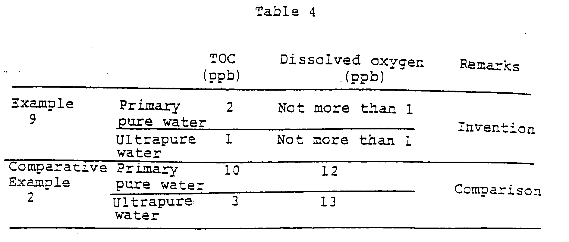
- Example 9 shows an example of the operation of the system shown in FIG. 7.
- the specification of each equipment used in Example 9 is as follows.
- Reverse osmosis membrane unit 34a Reverse osmosis membrane unit 34a :
- the operating conditions are as follows.
- Raw water city water of Atsugi city, Kanagawa, (TOC 800 ppb, electric conductivity 190 ⁇ S/cm, free chlorine 0.7 ppm as Cl 2 )
- the city water of Atsugi city was treated by activated carbon, and sulfuric acid was added thereto so as to adjust the pH to 5.5.
- the thus-treated water was passed through a two-stage reverse osmosis membrane equipment, and a mixed bed ion exchange tower. The water was then degased, thereby obtaining primary pure water.
- Vacuum degas tower
- the primary pure water was treated by the nonregeneration-type ion exchange resin and the UF membrane device after being oxidized by UV in the same way as in Example 8, thereby producing ultrapure water.
- FIG. 8 is a flowchart of a preferred system used in the present invention.
- Water such as city water or industrial water is supplied from a pipe 41 to a raw water tank 43.
- Waste semiconductor rinse water is introduced form a pipe 42 to the raw water tank 43.
- the raw water in the raw water tank 43 is introduced to a first heat exchanger 46 through a raw water pump 44 and a pipe 45 and heated.
- the heated water is supplied to a second heat exchanger 48 through a pipe 47 so as to be further heated.
- the water heated by the heat exchanger 48 is introduced to a third heat exchanger 50 through a pipe 49.
- the third heat exchanger 50 uses a steam heater as a heating source, and the water is heated to 130°C.
- H 2 SO 4 and Na 2 S 2 O 8 are added to the heated water, which is introduced to a reaction vessel 52 through a pipe 51.
- the reaction vessel 52 is a hollow vessel, but it may be packed with a catalyst, if necessary.
- the organic matter contained in the raw water is sufficiently decomposed.
- the decomposed water is introduced to a high-temperature degas tower 55 through a pipe 53 and a pressure control valve 54.
- a condensed water collector 58 is connected to the upper portion of the high-temperature degas tower 55 through pipes 56, 57.
- the pipe 56 is connected to a pipe on the heating source fluid side of the first heat exchanger 46, and the gas extracted from the high-temperature degas tower 55 is passed through the pipe on the heating source fluid side of the first heat exchanger 46 so as to be heat-exchanged with the raw water which is introduced from the pipe 45.
- the heat-exchanged gas is condensed, collected by the condensate water collector 58, and returned to the raw water tank 43.
- the water degassed by the high-temperature degas tower 55 is drawn out from the bottom portion of the tower 55 through a pipe 62 and a pump 63, and introduced to a pipe on the heating source fluid side of the second heat exchanger 48. After the water is heat-exchanged, it is introduced to a tank 65 through a pipe 64, and temporarily stored therein.
- the water in the tank 65 is introduced to a reverse osmosis membrane unit 68 through a pump 66 and a pipe 67 so as to be subjected to reverse osmosis treatment.
- the concentrated water of the unit 68 is taken out through a pipe 69 and disposed.
- the permeated water from the unit 68 is introduced to a tank 71 through a pipe 70, and further to a mixed bed ion exchange tower 74 through a pump 72 and a pipe 73.
- the demineralized water is introduced to a loose reverse osmosis membrane unit (or ultrafiltration membrane unit ) 76 through a pipe 75.
- the loose reverse osmosis membrane unit 76 is provided with a reverse osmosis membrane having a low salt removal rate such as 30 to 50%.
- the concentrated water from the loose reverse osmosis membrane unit 76 is returned to the tank 65 through a pipe 77.
- the permeated water from the unit 76 is primary pure water, and is introduced to a primary pure water tank 79 through a pipe 78.
- the primary pure water is introduced to a low-pressure mercury ultraviolet oxidization unit 82 through a pump 80 and a pipe 81 so as to be irradiated with ultraviolet.
- the water is then introduced to a nonregeneration-type ion exchange column 84 through a pipe 83, and further to an ultrafiltration membrane device 86 through a pipe 85.
- the permeated water from the device 86 is supplied to a usepoint through a pipe 87 as ultrapure water.
- the excess ultrapure water is returned from the device 86 to the primary pure water tank 79.
- the concentrated water from the device 86 is discharged out through a pie 88.
- a reverse osmosis membrane unit may be used in place of the mix bed ion exchange column 74.
- the reverse osmosis unit 68 and the mix bed ion exchange tower 74 may be changed with each other.
- a two- tower demineralization equipment which is composed of a cation exchange tower and an anion exchange tower connected in series may be used in place of the mixed bed ion exchange tower 74.
- waste semiconductor rinse water is introduced with city water or industrial water to the raw water tank 43, but only either of them may be introduced.
- City water contains components for hardness such as calcium and magnesium ions
- waste semiconductor rinse water contains fluoride ions. Consequently, if city water and waste semiconductor rinse water are mixed with each other as they are, insoluble compounds such as CaF 2 are produced. It is therefore preferable to remove the components for hardness by bringing the water into contact with a strong acidic cation exchange resin or to remove fluoride ions by bringing the waste semiconductor rinse water into contact with an anion exchange resin (e.g., a weak basic anion exchange resin having a good regeneration efficiency) before the city water and the waste semiconductor rinse water are mixed with each other. Both pretreatments may be adopted. Alternatively, after the city water is mixed with the waste semiconductor rinse water without any pretreatment, the insoluble compounds produced may be filtered out.
- anion exchange resin e.g., a weak basic anion exchange resin having a good regeneration efficiency
- reaction vessel 52 in the example is not packed with any catalyst, it may be packed with a catalyst.
- the method of producing pure water of the present invention it is possible to produce ultrapure water which has greatly reduced TOC and a very high degree of purity from raw water such as city water, well water and industrial water. According to the present invention, it is possible to reduce the dissolved oxygen in pure water. In addition, according to the present invention, the system is simplified.
Landscapes
- Chemical & Material Sciences (AREA)
- Organic Chemistry (AREA)
- Life Sciences & Earth Sciences (AREA)
- Hydrology & Water Resources (AREA)
- Engineering & Computer Science (AREA)
- Environmental & Geological Engineering (AREA)
- Water Supply & Treatment (AREA)
- Chemical Kinetics & Catalysis (AREA)
- Physics & Mathematics (AREA)
- Thermal Sciences (AREA)
- Health & Medical Sciences (AREA)
- Toxicology (AREA)
- Separation Using Semi-Permeable Membranes (AREA)
- Physical Water Treatments (AREA)
- Treatment Of Water By Oxidation Or Reduction (AREA)
- Treatment Of Water By Ion Exchange (AREA)
Abstract
Description
- pH:
- 2 to 4
- Acid component:
- hydrochloric acid, nitric acid, sulfuric acid, hydrofluoric acid
- Alkali component:
- ammonia
- TOC:
- 1 to 3 ppm
[TOC component: isopropyl alcohol, methanol, acetone, surfactant] - H2O2:
- about 20 ppm


(1 ppm of isopropyl alcohol, 0.5 ppm of acetone and 0.5 ppm of methanol)
(Na2S2O8 concentration in the treated water
(pH of the treated water: 4.5)

(1 ppm of isopropyl alcohol, 0.25 ppm of acetone, 0.25 ppm of methanol and 1 ppm of surfactant)
(Na2S2O8 concentration in the treated water)
- (isopropyl alcohol
- 40%
- surfactant
- 10%
- acetone
- 10%
- methanol
- 10%
- organic matter in the city water
- 30%
(K2S2O8 concentration in the treated water)
(pH of the treated water: 3)
(without oxidation catalyst)
(K2S2O8 concentration in the treated water)
Claims (6)
- A method of producing pure water from raw water containing hydrofluoric acid and TOC components comprising:contacting the raw water with a weak basic anion exchange resin to remove fluoride ions from the raw water,making the raw water acidic so that the pH is not more than 4.5 and heating in the presence of an oxidizing agent to thermally decompose the TOC components in said raw water, anddeionizing the raw water.
- A method of producing pure water according to claim 1, wherein the step of making the raw water acidic and heating in the presence of an oxidizing agent is effected by adding an oxidizing agent and an acid to the raw water and heating the resultant mixture.
- A method of producing pure water according to either of claims 1 and 2, wherein said raw water contains hydrogen peroxide, and a persulfate is added to said raw water prior to the thermal decomposition.
- A method of producing pure water according to any one of claims 1 to 3, wherein after the thermal decomposition, the raw water is degassed at a high temperature, and then deionized.
- A method of producing pure water according to any one of claims 1 and 4, wherein thermal decomposition of said TOC components in the raw water is conducted at 110 to 170°C for 2 to 5 minutes.
- A method of producing pure water according to claim 5, wherein the temperature for said thermal decomposition is 130 to 150°C.
Applications Claiming Priority (3)
| Application Number | Priority Date | Filing Date | Title |
|---|---|---|---|
| JP16281/93 | 1993-02-03 | ||
| JP1628193 | 1993-02-03 | ||
| PCT/JP1994/000152 WO1994018127A1 (en) | 1993-02-03 | 1994-02-03 | Pure water manufacturing method |
Publications (3)
| Publication Number | Publication Date |
|---|---|
| EP0634364A1 EP0634364A1 (en) | 1995-01-18 |
| EP0634364A4 EP0634364A4 (en) | 1995-06-14 |
| EP0634364B1 true EP0634364B1 (en) | 1999-01-07 |
Family
ID=11912173
Family Applications (1)
| Application Number | Title | Priority Date | Filing Date |
|---|---|---|---|
| EP94905834A Expired - Lifetime EP0634364B1 (en) | 1993-02-03 | 1994-02-03 | Pure water manufacturing method |
Country Status (6)
| Country | Link |
|---|---|
| US (1) | US5571419A (en) |
| EP (1) | EP0634364B1 (en) |
| JP (1) | JP3180348B2 (en) |
| KR (1) | KR0181533B1 (en) |
| DE (1) | DE69415736T2 (en) |
| WO (1) | WO1994018127A1 (en) |
Families Citing this family (48)
| Publication number | Priority date | Publication date | Assignee | Title |
|---|---|---|---|---|
| US5722442A (en) * | 1994-01-07 | 1998-03-03 | Startec Ventures, Inc. | On-site generation of ultra-high-purity buffered-HF for semiconductor processing |
| JP3259557B2 (en) | 1994-12-28 | 2002-02-25 | 栗田工業株式会社 | How to remove organic matter |
| JPH08262699A (en) * | 1995-03-28 | 1996-10-11 | Canon Inc | Resist composition, resist processing method and apparatus |
| JP3518112B2 (en) * | 1995-12-06 | 2004-04-12 | 東京瓦斯株式会社 | Fuel cell water treatment equipment |
| JP3742451B2 (en) * | 1996-01-17 | 2006-02-01 | 昌之 都田 | Cleaning method |
| KR100207469B1 (en) * | 1996-03-07 | 1999-07-15 | 윤종용 | Cleaning solution for semiconductor substrate and cleaning method thereby |
| DE19625346A1 (en) * | 1996-06-25 | 1998-01-02 | Joseph Dipl Ing Maier | Process for water treatment in a closed circuit with a reactor |
| US5925255A (en) * | 1997-03-01 | 1999-07-20 | Mukhopadhyay; Debasish | Method and apparatus for high efficiency reverse osmosis operation |
| US8758720B2 (en) * | 1996-08-12 | 2014-06-24 | Debasish Mukhopadhyay | High purity water produced by reverse osmosis |
| US6537456B2 (en) | 1996-08-12 | 2003-03-25 | Debasish Mukhopadhyay | Method and apparatus for high efficiency reverse osmosis operation |
| US20020153319A1 (en) | 1997-08-12 | 2002-10-24 | Debasish Mukhopadhyay | Method and apparatus for high efficiency reverse osmosis operation |
| EP0832852A3 (en) * | 1996-09-30 | 1998-07-29 | Peroxid-Chemie GmbH | Process for degrading noxious substances |
| KR100251649B1 (en) * | 1997-04-22 | 2000-04-15 | 윤종용 | Sterilizing composition for manufacturing high-purity water for using semiconductor device fabrication and sterilizing method of high-purity water manufacturing apparatus by using the sterilizing composition |
| AU7374098A (en) * | 1997-05-16 | 1998-12-08 | Pure Water, Inc. | Water distiller system for medical applications |
| CA2294129C (en) | 1997-06-19 | 2011-09-13 | Applied Specialties, Inc. | Water treatment process |
| US6398965B1 (en) * | 1998-03-31 | 2002-06-04 | United States Filter Corporation | Water treatment system and process |
| US6328896B1 (en) * | 1998-04-24 | 2001-12-11 | United States Filter Corporation | Process for removing strong oxidizing agents from liquids |
| EP0995803A3 (en) * | 1998-10-20 | 2001-11-07 | Matsushita Electric Industrial Co., Ltd. | Sample treating kit and sample treating method using the same for analysis with a biosensor |
| US6325983B1 (en) | 2000-04-19 | 2001-12-04 | Seh America, Inc. | Nox scrubbing system and method |
| US6306197B1 (en) | 2000-04-19 | 2001-10-23 | Seh America, Inc. | Isopropyl alcohol scrubbing system |
| KR100689693B1 (en) * | 2000-12-19 | 2007-03-08 | 삼성전자주식회사 | Ultrapure Water Production Method |
| JP2002282850A (en) * | 2001-03-26 | 2002-10-02 | Mitsubishi Electric Corp | Ultrapure water production equipment |
| US7247240B2 (en) * | 2002-03-11 | 2007-07-24 | Nippon Shokubai Co., Ltd. | Method for treating waste water |
| US7216702B2 (en) | 2003-02-28 | 2007-05-15 | Yates Petroleum Corporation | Methods of evaluating undersaturated coalbed methane reservoirs |
| FR2857753B1 (en) * | 2003-07-18 | 2006-05-05 | Millipore Corp | ANALYZER APPARATUS EQUIPPED WITH MEANS FOR PURIFYING WATER |
| EP1707538A4 (en) * | 2004-01-22 | 2008-05-21 | Idemitsu Kosan Co | PROCESS FOR TREATING RAW WATER CONTAINING LITTLE DECOMPOSABLE SUBSTANCES |
| WO2007146671A2 (en) * | 2006-06-06 | 2007-12-21 | Fluid Lines | Ultaviolet light activated oxidation process for the reduction of organic carbon in semiconductor process water |
| US12103874B2 (en) * | 2006-06-06 | 2024-10-01 | Evoqua Water Technologies Llc | Ultraviolet light activated oxidation process for the reduction of organic carbon in semiconductor process water |
| US10343939B2 (en) * | 2006-06-06 | 2019-07-09 | Evoqua Water Technologies Llc | Ultraviolet light activated oxidation process for the reduction of organic carbon in semiconductor process water |
| US8753522B2 (en) * | 2007-04-03 | 2014-06-17 | Evoqua Water Technologies Llc | System for controlling introduction of a reducing agent to a liquid stream |
| US8961798B2 (en) | 2007-04-03 | 2015-02-24 | Evoqua Water Technologies Llc | Method for measuring a concentration of a compound in a liquid stream |
| US8741155B2 (en) | 2007-04-03 | 2014-06-03 | Evoqua Water Technologies Llc | Method and system for providing ultrapure water |
| US9365436B2 (en) | 2007-04-03 | 2016-06-14 | Evoqua Water Technologies Llc | Method of irradiating a liquid |
| US9365435B2 (en) | 2007-04-03 | 2016-06-14 | Evoqua Water Technologies Llc | Actinic radiation reactor |
| US9725343B2 (en) | 2007-04-03 | 2017-08-08 | Evoqua Water Technologies Llc | System and method for measuring and treating a liquid stream |
| US8486684B2 (en) * | 2007-08-13 | 2013-07-16 | Frito-Lay North America, Inc. | Method for increasing asparaginase activity in a solution |
| US7520993B1 (en) * | 2007-12-06 | 2009-04-21 | Water & Power Technologies, Inc. | Water treatment process for oilfield produced water |
| TWI428290B (en) * | 2008-12-03 | 2014-03-01 | Rainer Bauder | Systems and methods for wastewater treatment |
| US8591730B2 (en) | 2009-07-30 | 2013-11-26 | Siemens Pte. Ltd. | Baffle plates for an ultraviolet reactor |
| JP5678436B2 (en) * | 2010-03-04 | 2015-03-04 | 栗田工業株式会社 | Ultrapure water production method and apparatus |
| EP2527301B1 (en) | 2011-05-26 | 2016-04-27 | Evoqua Water Technologies GmbH | Method and arrangement for a water treatment |
| JP6533359B2 (en) * | 2013-10-07 | 2019-06-19 | 野村マイクロ・サイエンス株式会社 | Ultra pure water production method |
| KR20160107159A (en) * | 2013-11-11 | 2016-09-13 | 필리페 라이첸 | A process for removing urea from water |
| US11161762B2 (en) | 2015-01-21 | 2021-11-02 | Evoqua Water Technologies Llc | Advanced oxidation process for ex-situ groundwater remediation |
| US10494281B2 (en) | 2015-01-21 | 2019-12-03 | Evoqua Water Technologies Llc | Advanced oxidation process for ex-situ groundwater remediation |
| IT201600080132A1 (en) * | 2016-07-29 | 2018-01-29 | Nigris Vitantonio De | PLANT FOR WASTEWATER TREATMENT AND ITS PROCEDURE. |
| SMP201600255B (en) * | 2016-07-29 | 2016-08-31 | Vitantonio De Nigris | PLANT FOR WASTEWATER TREATMENT AND ITS PROCEDURE |
| CN107352699B (en) * | 2017-09-06 | 2018-08-17 | 深圳市龙岗区东江工业废物处置有限公司 | A Wastewater Purification System |
Family Cites Families (32)
| Publication number | Priority date | Publication date | Assignee | Title |
|---|---|---|---|---|
| DE149799C (en) * | ||||
| CA971506A (en) * | 1972-04-05 | 1975-07-22 | John R. Moyer | Treatment of brines by chlorination |
| US3870033A (en) * | 1973-11-30 | 1975-03-11 | Aqua Media | Ultra pure water process and apparatus |
| JPS5548876A (en) * | 1978-10-05 | 1980-04-08 | Olympus Optical Co Ltd | Retrieval unit for tape cassette |
| DE2852475C2 (en) * | 1978-12-05 | 1980-05-22 | Deutsche Gold- Und Silber-Scheideanstalt Vormals Roessler, 6000 Frankfurt | Process for the automatically controllable detoxification of wastewater containing nitrite ions |
| DD149799A1 (en) * | 1980-03-10 | 1981-07-29 | Volker Vobach | METHOD FOR PRODUCING ORGANIC-CHEMICAL ULTRAREINIC WATER IN THE LABORATORY |
| DE3125452C2 (en) * | 1981-06-29 | 1985-09-12 | Degussa Ag, 6000 Frankfurt | Process for detoxifying and lowering the COD and the BOD in continuous wastewater streams with changing contents of various oxidizable ingredients with hydrogen peroxide |
| JPS60212288A (en) * | 1984-04-05 | 1985-10-24 | Mitsubishi Metal Corp | Treatment of waste water containing ammonium ion and fluorine ion |
| US4594170A (en) * | 1984-06-25 | 1986-06-10 | Fmc Corporation | Method for liquifying chloride-based heavy brine well completion fluids |
| US4595498A (en) * | 1984-12-27 | 1986-06-17 | Thomson Components-Mostek Corporation | Water-polishing loop |
| JPS62193696A (en) * | 1986-02-20 | 1987-08-25 | Nomura Micro Sci Kk | Production of extremely pure water |
| US4751005A (en) * | 1986-08-22 | 1988-06-14 | Nippon Shokubai Kagaku Kogyo Co., Ltd. | Method for treatment of waste water |
| US4767543A (en) * | 1986-11-13 | 1988-08-30 | Universite De Sherbrooke | Oxidation of wastewaters |
| US4792407A (en) * | 1986-11-25 | 1988-12-20 | Ultrox International | Oxidation of organic compounds in water |
| DE3884435T2 (en) * | 1987-03-25 | 1994-02-17 | Hitachi Ltd | Processes for producing high-purity water and process for using this water. |
| US4990260A (en) * | 1988-01-28 | 1991-02-05 | The Water Group, Inc. | Method and apparatus for removing oxidizable contaminants in water to achieve high purity water for industrial use |
| US4861484A (en) * | 1988-03-02 | 1989-08-29 | Synlize, Inc. | Catalytic process for degradation of organic materials in aqueous and organic fluids to produce environmentally compatible products |
| JPH0217994A (en) * | 1988-07-07 | 1990-01-22 | Toshiba Corp | Ultrapure water producer |
| JP2768732B2 (en) * | 1989-05-01 | 1998-06-25 | 神鋼パンテック株式会社 | Heat degassing ultrapure water equipment |
| JPH0753276B2 (en) * | 1989-10-03 | 1995-06-07 | 栗田工業株式会社 | Fluoride-containing water treatment method |
| US5061374A (en) * | 1989-12-18 | 1991-10-29 | Micron Technology, Inc. | Reverse osmosis as final filter in ultrapure deionized water system |
| JPH0647105B2 (en) * | 1989-12-19 | 1994-06-22 | 株式会社荏原総合研究所 | Purification method and device for pure water or ultrapure water |
| US5232604A (en) * | 1990-01-31 | 1993-08-03 | Modar, Inc. | Process for the oxidation of materials in water at supercritical temperatures utilizing reaction rate enhancers |
| US5106513A (en) * | 1990-01-31 | 1992-04-21 | Modar, Inc. | Process for oxidation of materials in water at supercritical temperatures and subcritical pressures |
| JP2520317B2 (en) * | 1990-03-14 | 1996-07-31 | 日立造船株式会社 | Ultrapure water production apparatus and method |
| JPH0790219B2 (en) * | 1990-08-01 | 1995-10-04 | 日本錬水株式会社 | Pure water production apparatus and production method |
| US5141717A (en) * | 1990-12-24 | 1992-08-25 | Ionics, Incorporated | Carbon monitor containing anion exchange resin |
| JPH0557300A (en) * | 1991-09-04 | 1993-03-09 | Hitachi Ltd | Ultrapure water production system |
| JP2902511B2 (en) * | 1991-12-24 | 1999-06-07 | 三菱電機株式会社 | Ultrapure water production apparatus, production method, and production apparatus control method |
| KR960016302B1 (en) * | 1992-05-15 | 1996-12-09 | 마쯔시다덴기산교 가부시기가이샤 | Pure water production apparatus and pure water production method |
| JP3468784B2 (en) * | 1992-08-25 | 2003-11-17 | 栗田工業株式会社 | Ultrapure water production equipment |
| US5356539A (en) * | 1993-03-19 | 1994-10-18 | Air Products And Chemicals, Inc. | Tandem waste stream treatment for the removal of nitroaromatics and nitrophenolics |
-
1994
- 1994-02-03 WO PCT/JP1994/000152 patent/WO1994018127A1/en not_active Ceased
- 1994-02-03 US US08/302,806 patent/US5571419A/en not_active Expired - Lifetime
- 1994-02-03 KR KR1019940703420A patent/KR0181533B1/en not_active Expired - Lifetime
- 1994-02-03 JP JP51787394A patent/JP3180348B2/en not_active Expired - Fee Related
- 1994-02-03 DE DE69415736T patent/DE69415736T2/en not_active Expired - Lifetime
- 1994-02-03 EP EP94905834A patent/EP0634364B1/en not_active Expired - Lifetime
Also Published As
| Publication number | Publication date |
|---|---|
| DE69415736T2 (en) | 1999-05-20 |
| DE69415736D1 (en) | 1999-02-18 |
| US5571419A (en) | 1996-11-05 |
| EP0634364A1 (en) | 1995-01-18 |
| EP0634364A4 (en) | 1995-06-14 |
| JP3180348B2 (en) | 2001-06-25 |
| KR950700859A (en) | 1995-02-20 |
| WO1994018127A1 (en) | 1994-08-18 |
| KR0181533B1 (en) | 1999-04-01 |
Similar Documents
| Publication | Publication Date | Title |
|---|---|---|
| US5571419A (en) | Method of producing pure water | |
| JPWO1994018127A1 (en) | Pure water production method | |
| US6464867B1 (en) | Apparatus for producing water containing dissolved ozone | |
| JPH0790219B2 (en) | Pure water production apparatus and production method | |
| KR20050062548A (en) | Method of removing organic impurities from water | |
| WO1999050184A1 (en) | Water treatment system and process comprising ph-adjustment | |
| JPH0647105B2 (en) | Purification method and device for pure water or ultrapure water | |
| JP4045658B2 (en) | Pure water production method | |
| JP4599803B2 (en) | Demineralized water production equipment | |
| JP6533359B2 (en) | Ultra pure water production method | |
| JP3413883B2 (en) | Pure water production equipment | |
| JP2000015257A (en) | Apparatus and method for producing high-purity water | |
| JP2002210494A (en) | Ultrapure water production equipment | |
| JPH0649190B2 (en) | High-purity water manufacturing equipment | |
| JP3259557B2 (en) | How to remove organic matter | |
| JP3081079B2 (en) | Decarbonation equipment and pure water production equipment incorporating the equipment | |
| JP2012196630A (en) | Treatment equipment and treatment method of acid liquid | |
| JP6629383B2 (en) | Ultrapure water production method | |
| JPH0929251A (en) | Ultrapure water production equipment | |
| JP2002355683A (en) | Ultrapure water production method and ultrapure water production equipment | |
| JPH09294974A (en) | Water treatment apparatus | |
| JPH1099853A (en) | Treatment system for water containing tetraalkylammonium hydroxide | |
| JPH10216749A (en) | Ultrapure water making apparatus | |
| JP3992996B2 (en) | Wastewater treatment method and apparatus | |
| JP3304412B2 (en) | Pure water production method |
Legal Events
| Date | Code | Title | Description |
|---|---|---|---|
| PUAI | Public reference made under article 153(3) epc to a published international application that has entered the european phase |
Free format text: ORIGINAL CODE: 0009012 |
|
| 17P | Request for examination filed |
Effective date: 19940921 |
|
| AK | Designated contracting states |
Kind code of ref document: A1 Designated state(s): DE FR GB |
|
| A4 | Supplementary search report drawn up and despatched | ||
| AK | Designated contracting states |
Kind code of ref document: A4 Designated state(s): DE FR GB |
|
| 17Q | First examination report despatched |
Effective date: 19971006 |
|
| GRAG | Despatch of communication of intention to grant |
Free format text: ORIGINAL CODE: EPIDOS AGRA |
|
| GRAG | Despatch of communication of intention to grant |
Free format text: ORIGINAL CODE: EPIDOS AGRA |
|
| GRAH | Despatch of communication of intention to grant a patent |
Free format text: ORIGINAL CODE: EPIDOS IGRA |
|
| GRAH | Despatch of communication of intention to grant a patent |
Free format text: ORIGINAL CODE: EPIDOS IGRA |
|
| GRAA | (expected) grant |
Free format text: ORIGINAL CODE: 0009210 |
|
| AK | Designated contracting states |
Kind code of ref document: B1 Designated state(s): DE FR GB |
|
| REF | Corresponds to: |
Ref document number: 69415736 Country of ref document: DE Date of ref document: 19990218 |
|
| ET | Fr: translation filed | ||
| PLBE | No opposition filed within time limit |
Free format text: ORIGINAL CODE: 0009261 |
|
| STAA | Information on the status of an ep patent application or granted ep patent |
Free format text: STATUS: NO OPPOSITION FILED WITHIN TIME LIMIT |
|
| 26N | No opposition filed | ||
| REG | Reference to a national code |
Ref country code: GB Ref legal event code: IF02 |
|
| PGFP | Annual fee paid to national office [announced via postgrant information from national office to epo] |
Ref country code: GB Payment date: 20101216 Year of fee payment: 18 |
|
| PGFP | Annual fee paid to national office [announced via postgrant information from national office to epo] |
Ref country code: FR Payment date: 20120202 Year of fee payment: 19 |
|
| PGFP | Annual fee paid to national office [announced via postgrant information from national office to epo] |
Ref country code: DE Payment date: 20120327 Year of fee payment: 19 |
|
| GBPC | Gb: european patent ceased through non-payment of renewal fee |
Effective date: 20130203 |
|
| REG | Reference to a national code |
Ref country code: FR Ref legal event code: ST Effective date: 20131031 |
|
| REG | Reference to a national code |
Ref country code: DE Ref legal event code: R119 Ref document number: 69415736 Country of ref document: DE Effective date: 20130903 |
|
| PG25 | Lapsed in a contracting state [announced via postgrant information from national office to epo] |
Ref country code: FR Free format text: LAPSE BECAUSE OF NON-PAYMENT OF DUE FEES Effective date: 20130228 Ref country code: DE Free format text: LAPSE BECAUSE OF NON-PAYMENT OF DUE FEES Effective date: 20130903 Ref country code: GB Free format text: LAPSE BECAUSE OF NON-PAYMENT OF DUE FEES Effective date: 20130203 |