EP0633182B1 - Strukturbauteil, insbesondere für Automobile, mit einem verhältnismässig leichten und weichen Metall und Verfahren zur Herstellung - Google Patents
Strukturbauteil, insbesondere für Automobile, mit einem verhältnismässig leichten und weichen Metall und Verfahren zur Herstellung Download PDFInfo
- Publication number
- EP0633182B1 EP0633182B1 EP19940401551 EP94401551A EP0633182B1 EP 0633182 B1 EP0633182 B1 EP 0633182B1 EP 19940401551 EP19940401551 EP 19940401551 EP 94401551 A EP94401551 A EP 94401551A EP 0633182 B1 EP0633182 B1 EP 0633182B1
- Authority
- EP
- European Patent Office
- Prior art keywords
- plate
- metal
- grid
- structural element
- parts
- Prior art date
- Legal status (The legal status is an assumption and is not a legal conclusion. Google has not performed a legal analysis and makes no representation as to the accuracy of the status listed.)
- Expired - Lifetime
Links
Images


Classifications
-
- B—PERFORMING OPERATIONS; TRANSPORTING
- B60—VEHICLES IN GENERAL
- B60J—WINDOWS, WINDSCREENS, NON-FIXED ROOFS, DOORS, OR SIMILAR DEVICES FOR VEHICLES; REMOVABLE EXTERNAL PROTECTIVE COVERINGS SPECIALLY ADAPTED FOR VEHICLES
- B60J5/00—Doors
- B60J5/04—Doors arranged at the vehicle sides
- B60J5/042—Reinforcement elements
- B60J5/045—Panel type elements
-
- B—PERFORMING OPERATIONS; TRANSPORTING
- B60—VEHICLES IN GENERAL
- B60J—WINDOWS, WINDSCREENS, NON-FIXED ROOFS, DOORS, OR SIMILAR DEVICES FOR VEHICLES; REMOVABLE EXTERNAL PROTECTIVE COVERINGS SPECIALLY ADAPTED FOR VEHICLES
- B60J5/00—Doors
- B60J5/04—Doors arranged at the vehicle sides
- B60J5/042—Reinforcement elements
- B60J5/0422—Elongated type elements, e.g. beams, cables, belts or wires
- B60J5/0438—Elongated type elements, e.g. beams, cables, belts or wires characterised by the type of elongated elements
- B60J5/0441—Elongated type elements, e.g. beams, cables, belts or wires characterised by the type of elongated elements the elements having a grid-like structure, i.e. interconnected or interwoven elements
-
- B—PERFORMING OPERATIONS; TRANSPORTING
- B62—LAND VEHICLES FOR TRAVELLING OTHERWISE THAN ON RAILS
- B62D—MOTOR VEHICLES; TRAILERS
- B62D21/00—Understructures, i.e. chassis frame on which a vehicle body may be mounted
- B62D21/15—Understructures, i.e. chassis frame on which a vehicle body may be mounted having impact absorbing means, e.g. a frame designed to permanently or temporarily change shape or dimension upon impact with another body
-
- B—PERFORMING OPERATIONS; TRANSPORTING
- B62—LAND VEHICLES FOR TRAVELLING OTHERWISE THAN ON RAILS
- B62D—MOTOR VEHICLES; TRAILERS
- B62D25/00—Superstructure or monocoque structure sub-units; Parts or details thereof not otherwise provided for
- B62D25/02—Side panels
-
- B—PERFORMING OPERATIONS; TRANSPORTING
- B62—LAND VEHICLES FOR TRAVELLING OTHERWISE THAN ON RAILS
- B62D—MOTOR VEHICLES; TRAILERS
- B62D29/00—Superstructures, understructures, or sub-units thereof, characterised by the material thereof
Definitions
- the present invention relates to a structural element, in particular for a vehicle, comprising a plate made of a relatively light and soft first metal or alloy. It also relates to a process relating thereto and intended to improve the properties of such a structural element.
- the present invention relates in particular to land, air or sea vehicles. Most often, the body, fuselage or hull of these vehicles is largely made of thin sheets assembled together.
- the bodywork consists in particular of steel sheets the thickness of which is close to one millimeter and which are crimped, welded or riveted.
- steel has two major drawbacks: its density is high, which makes it relatively heavy. In addition, it is very sensitive to corrosion. Of course, the steel can be subjected to various surface treatments or else have a chemical composition increasing its resistance to corrosion. However, the success of these anti-corrosion methods is often partial and corrosion is generally inevitable in the long term.
- the object of the invention is to overcome these drawbacks and produce structural elements, having increased mechanical strength for a small thickness, which are light and inexpensive.
- the invention therefore relates to a structural element, in particular for a vehicle comprising a plate made of a relatively light and soft first metal or alloy.
- the structural element is characterized in that the plate has on one of its faces in a predetermined limited area of said face a part having the shape of an openwork sheet or a grid made in a second metal or alloy harder than that of the plate, said part being fixed to the plate by cold stamping, so that the metal of the plate penetrates into the openings of the part.
- the part is fixed in a limited area of the face of the plate.
- the total weight of the structural element is therefore not increased significantly.
- the part contributes to considerably increasing the mechanical resistance of the structural element, mainly in the fixing zone.
- the element therefore largely retains the advantages of the first metal, in particular its lightness and possibly its insensitivity to corrosion while exhibiting increased mechanical resistance.
- the invention therefore makes it possible to locally strengthen the mechanical strength of the structural element without significantly increasing its weight or its total cost. In addition, it is not necessary to give the stamped part a significant thickness. We can even often give it a thickness significantly smaller than that of the plate.
- fixing the part as indicated ensures a simple and robust anchoring of the part in the plate and a very good mechanical connection between the two metals.
- the joining of steel and aluminum by riveting would not ensure a continuous mechanical connection of the two metals and the presence of the rivets would generate extra thicknesses.
- At least one part of the part has a lower perforation density than other parts of the part.
- Perforation density denotes the ratio over a given part of the surface of the part, between the surface covered by the perforations or openings and the total surface of the part.
- the perforation density is high when the perforations or openings are numerous and / or have large dimensions.
- the density is low in contrary cases.
- the parts with a low perforation density give a particularly strong mechanical resistance to the parts of the plate in which they are anchored, because the proportion of steel by mass is important there. On the contrary, the parts with a low perforation density moderately increase the resistance of the structural element. It is therefore possible to further strengthen the resistance of the parts of the plate which will be subjected to particularly high stresses.
- perforation density will be used even when the openings of the part do not result from a perforation operation, for example in the case of a grid made up of interlaced wires.
- the first metal is aluminum and the second metal is steel.
- the plate has at least two of said parts, these two parts being separated from one another.
- the invention also relates to a method for improving the properties of a structural element, in particular for a vehicle, comprising a plate made of a first metal or alloy which is relatively light and soft.
- this method comprises a step consisting in fixing in a predetermined limited area of one of the faces of the plate a part having the form of an openwork sheet or a grid made of a second metal of harder alloy than that of the plate, this fixing being effected by cold stamping, so that the metal of the plate penetrates into the openings of the part.
- the plate undergoes a stamping operation to give it a predetermined shape, the fixing of the part takes place during said stamping operation.
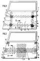
- FIG. 1 A first embodiment of a structural element according to the invention is shown in Figure 1.
- This element 1 here constitutes the outer metal part of a car door.
- the element 1 comprises a plate 2 made of a first metal or relatively light and soft alloy, for example aluminum.
- the plate 2 on the inner face of the plate 2, visible in elevation in FIG. 1, the plate 2 has a part 3 fixed on a predetermined limited area of said face.
- the part 3 has, in this example, the shape of a grid and is made of a second metal or alloy harder than that of the plate 2.
- this second metal is steel.
- the grid 3 consists of a perforated sheet.
- the grid 3 could also consist of interlaced wires.
- the part 3 is fixed to the plate 2 by cold stamping, so that the metal of the plate 2 penetrates into the openings of the part 3.
- the part 3 has been completely embedded in the plate 2, the metal of which has filled the openings 6 of the part 3.
- the part 3 no longer protrudes from the upper face of the plate 2.
- the grid 3 comprises four interlaced bands 7, 8, 9, 10, two bands 7 and 8 being horizontal and two bands 9 and 10 being vertical.
- the part 3 has a hollowed-out central part 11.
- the part 3 could also consist of a single-piece grid hollowed out in the central part.
- the parts 12, 13, 14, 15 of the grid 3, located at the intersections of the strips 7, 8, 9 and 10 therefore have a lower perforation density than the other parts of the grid 3.
- the surface of the openings is therefore reduced compared to to the other parts of the grid 3.
- the plate 2 can also undergo at least one stamping operation intended to give it a particular predetermined shape in relation to the function of the structural element. This operation can take place after fixing the part or simultaneously with this fixing as we will see later. This operation can still precede the fixing of the part.
- the part will advantageously have a shape adapted to that of the plate. For example, it will also have been stamped to give it a shape corresponding to that of the plate.
- FIG. 2 shows another embodiment of the invention, similar to that of FIG. 1.
- Element 16 also constitutes the external metal part of a car door and comprises a plate 2 identical to that of FIG. 1.
- the plate 2 has on its inner face a grid 17 similar to the grid 3.
- the grid 17 has the general shape of a cross fixed on an area located substantially in the center of the lower part of the plate 2.
- the grid 17 comprises a horizontal strip 18 extending from one edge 19 to the other 20 of the plate 2 and a vertical strip 21 perpendicular to the strip 18.
- the plate 2 has four other similar grids 22, 23, 24, 25 separated from each other. These four grids are fixed on the same face of the plate 2 as the grid 17, respectively at the four corners of the lower part of the face of the plate 2. Thus, these four grids are fixed on areas close to the edges of the plate 2, as well as the ends 26 and 27 of the horizontal strip 18.
- the part 28 of the cross corresponding to the intersection of the horizontal and vertical bands, the ends 26 and 27 and the parts 22, 23, 24, 25 have a density of perforation lower than the other parts of the grid 17.
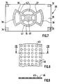
- FIG. 7 shows another embodiment of the invention.
- the element 60 consists of a rectangular aluminum plate 30. On one face thereof, four grids 31, 32, 33, 34 were fixed by cold stamping respectively to the four corners of the plate as well. a grid 35 over an area located substantially in the center of the plate.
- the grid 35 has the following form: it has two bands 36 and 37 arranged substantially along the diagonals of the rectangle. Two bands 38, 39 in an arc respectively join the ends of each band closest to each other.
- the grid has the shape of a disc 40 at the point of intersection of the strips 36 and 37. It has between the two strips 38 and 39 a circle 41 concentric with the disc 40 and distant from the latter.
- the grid 35 therefore has six recessed parts 42.
- the grids 31, 32, 33, 34 can be fixed to the four corners of the plate on the face opposite that which presents the grid 35, so that the grids are fixed on different faces of the plate 30.
- the grids 31, 32, 33, 34, 35 are made of harder metal than aluminum, for example steel.
- the parts anchored in the plate can alternatively consist of an perforated sheet 45, as in FIGS. 8 and 9.
- the sheet 45 is a sheet of hard metal, for example steel, in which openings or perforations 46 have been made, for example by means of a press.
- the perforation density on the sheet 45 can be varied as desired, by locally modifying the number and / or the dimensions of the perforations.
- FIG 12 there is shown a perforated sheet 60 whose perforation density is low in the central part due to the small diameter of the perforations 61 in this part.
- the openings shown in Figures 8 and 12 have a circular shape. However, the openings can have various shapes, for example square, hexagonal, etc.
- the invention also relates to a method for improving the properties of a structural element 1, in particular for a vehicle, comprising a plate 2 made of a relatively light and soft first metal or alloy.
- This process corresponds to the structural element according to the invention.
- the method comprises a step consisting in fixing in a predetermined limited area of one of the faces of the plate 2, a part 3, having the form of an openwork sheet or a grid made of a second metal. or a harder alloy than that of the plate, this fixing being effected by cold stamping, so that the metal of the plate 2 penetrates into the openings of the part 3.
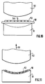
- Figures 10 and 11 show an advantageous mode of implementing the method according to the invention.
- the plate 50 to which it applies conventionally undergoes a stamping operation to give it a predetermined shape.
- the operation consists, for example here, in giving the initially planar plate 50 a curved shape.
- the fixing of the part 53 having the form of a grid or of a perforated sheet takes place during said die-stamping operation.
- the arrow 54 indicates the direction of movement of the movable part 52 towards the fixed part 51 for the purpose of stamping.
- the plate 50 and the part 53 are given the desired curvature and simultaneously the part 53 is pressed into the plate 50 to obtain the configuration described above.
- One of the main advantages of the structural element and of the method according to the invention is that the stamped part on the plate considerably increases the mechanical resistance of the latter and therefore of the structural element.
- the part can have a thickness that is substantially smaller than that of the plate.
- the anchoring of the part in the plate therefore does not significantly increase the weight of the element.
- the part is fixed on a predetermined limited area of the surface of the plate.
- This zone is determined in particular as a function of the mechanical stresses to which the structural element may be subjected during its use. Indeed, very often these constraints are particularly strong in certain places only of the element.
- the invention will advantageously be used in many fields where high mechanical strength and low weight are sought, such as land, air and sea vehicles or even the building industry.
Claims (10)
- Strukturbauteil (1; 16; 60), insbesondere für Fahrzeuge, mit einer Platte (2; 30) aus einem ersten, verhältnismäßig leichten und weichen Metall oder Metallegierung, dadurch gekennzeichnet, daß die Platte (2, 30) auf einer ihrer Flächen in einem vorgegebenen, begrenzten Bereich dieser Fläche ein Teil (3; 17; 35) in Form eines Lochblechs (45) oder eines Gitters (3) aus einem zweiten, gegenüber dem der Platte (2; 30) härteren Metall oder Metallegierung aufweist, wobei das Teil (3; 17, 22, 23, 24, 25; 31, 32, 33, 34, 35) auf der Platte durch Kaltverformung befestigt ist, so daß das Metall der Platte (2; 30) die Öffnungen (6; 46) des Teils (3; 17, 22, 23, 24, 25; 31, 32, 33, 34, 35) durchdringt.
- Bauteil nach Anspruch 1, dadurch gekennzeichnet, daß wenigstens ein Abschnitt (12, 13, 14, 15; 22, 23, 24, 25, 26, 27, 28) des Teils (3; 17) eine gegenüber anderen Abschnitten des Teils niedrigere Perforationsdichte aufweist.
- Bauteil nach einem der Ansprüche 1 oder 2, dadurch gekennzeichnet, daß das Teil wenigstens einen ausgesparten Abschnitt (11; 42) aufweist.
- Bauteil nach einem der Ansprüche 1 bis 3, dadurch gekennzeichnet, daß die Platte (2; 30) zwei dieser Teile aufweist, wobei die Teile auf derselben Fläche der Platte (2; 30) befestigt sind.
- Bauteil nach einen, der Ansprüche 1 bis 3, dadurch gekennzeichnet, daß die Platte (2; 30) wenigstens zwei dieser Teile aufweist, wobei die Teile auf verschiedenen Flächen der Platte befestigt sind.
- Bauteil nach einem der Ansprüche 1 bis 5, dadurch gekennzeichnet, daß das erste Metall Aluminium ist.
- Bauteil nach einem der Ansprüche 1 bis 6, dadurch gekennzeichnet, daß das zweite Metall Stahl ist.
- Verfahren zur Verbesserung der Eigenschaften eines Strukturbauteils (1; 16; 60), insbesondere für Fahrzeuge, mit einer Platte (2; 30; 50) aus einem ersten, verhältnismäßig leichten und weichen Metall oder Metallegierung, dadurch gekennzeichnet, daß das Verfahren einen ersten Schritt umfaßt, der darin besteht, in einem vorgegebenen, begrenzten Bereich einer der Flächen der Platte (2; 30; 50) ein Teil (3; 17, 22, 23, 24, 25; 31, 32, 33, 34, 35; 53) in Form eines Lochblechs (45) oder eines Gitters (3) aus einem gegenüber dem der Platte (2; 30; 50) härteren Metall zu befestigen, wobei diese Befestigung durch Kaltverformung stattfindet, so daß das Metall der Platte (2; 30; 50) die Öffnungen (6; 46) des Teils durchdringt.
- Verfahren nach Anspruch 8, wobei die Platte (50) einem Verformungsprozess unterworfen wird, um eine vorgegebene Form zu erhalten, dadurch gekennzeichnet, daß die Befestigung des Teils (53) während dieses Verformungsprozesses stattfindet.
- Verfahren nach einem der Ansprüche 8 bis 9, dadurch gekennzeichnet, daß man auf der Platte wenigstens eines der beiden Teile befestigt, wobei diese Teile voneinander getrennt sind.
Applications Claiming Priority (2)
| Application Number | Priority Date | Filing Date | Title |
|---|---|---|---|
| FR9308353 | 1993-07-07 | ||
| FR9308353A FR2707234B1 (fr) | 1993-07-07 | 1993-07-07 | Elément de structure, notamment pour véhicule, comprenant une plaque en métal relativement léger et mou, et procédé s'y rapportant. |
Publications (2)
| Publication Number | Publication Date |
|---|---|
| EP0633182A1 EP0633182A1 (de) | 1995-01-11 |
| EP0633182B1 true EP0633182B1 (de) | 1997-01-08 |
Family
ID=9449022
Family Applications (1)
| Application Number | Title | Priority Date | Filing Date |
|---|---|---|---|
| EP19940401551 Expired - Lifetime EP0633182B1 (de) | 1993-07-07 | 1994-07-06 | Strukturbauteil, insbesondere für Automobile, mit einem verhältnismässig leichten und weichen Metall und Verfahren zur Herstellung |
Country Status (4)
| Country | Link |
|---|---|
| EP (1) | EP0633182B1 (de) |
| DE (2) | DE633182T1 (de) |
| ES (1) | ES2070802T1 (de) |
| FR (1) | FR2707234B1 (de) |
Cited By (3)
| Publication number | Priority date | Publication date | Assignee | Title |
|---|---|---|---|---|
| EP0882639A2 (de) | 1997-06-02 | 1998-12-09 | Volkswagen Aktiengesellschaft | Karosserierahmenbauteil für die Karosserie eines Kraftfahrzeuges und Verfahren für dessen Herstellung |
| US6220653B1 (en) | 1998-08-17 | 2001-04-24 | Volkswagen Ag | Body component arrangement for a motor vehicle |
| CN102310832A (zh) * | 2010-06-28 | 2012-01-11 | 罗伯特·博世有限公司 | 用于车辆的车辆结构 |
Families Citing this family (6)
| Publication number | Priority date | Publication date | Assignee | Title |
|---|---|---|---|---|
| DE4437773C1 (de) * | 1994-10-24 | 1995-10-26 | Daimler Benz Ag | Instrumententafel mit einem integrierten, aufklappbaren Gassackdeckel |
| GB0107792D0 (en) * | 2001-03-28 | 2001-05-16 | Snow Jeremy A R | A vehicle body element |
| DE10254027B4 (de) * | 2002-11-20 | 2011-06-16 | Bayerische Motoren Werke Aktiengesellschaft | Kraftfahrzeug mit einer Seitenwand |
| US20120056445A1 (en) * | 2010-09-03 | 2012-03-08 | Ford Global Technologies, Llc | Body Panel and Reinforcement Assembly |
| DE102013012269A1 (de) * | 2013-07-24 | 2015-01-29 | GM Global Technology Operations LLC (n. d. Gesetzen des Staates Delaware) | Linienverstärktes Kraftfahrzeugblech, insbesondere Karosserieblech, sowie Verfahren zur Herstellung eines linienverstärkten Kraftfahrzeugblechs |
| DE102014018409A1 (de) | 2014-12-11 | 2016-06-16 | GM Global Technology Operations LLC (n. d. Ges. d. Staates Delaware) | Blech und Verfahren zu dessen Herstellung |
Family Cites Families (4)
| Publication number | Priority date | Publication date | Assignee | Title |
|---|---|---|---|---|
| FR664251A (fr) * | 1927-11-08 | 1929-08-31 | Matière composée de feuilles métalliques perforéés et de feuilles de matière thermoplastique et objets fabriqués à l'aide de cette matière composée | |
| US2237623A (en) * | 1935-01-31 | 1941-04-08 | Budd Edward G Mfg Co | Laminated sheet and stamped metal panel |
| JPS56153137A (en) * | 1980-04-28 | 1981-11-27 | Yokohama Rubber Co Ltd:The | Vibration damping and reinforcing method of thin plate component |
| DE4103036A1 (de) * | 1991-02-01 | 1992-08-06 | Bayerische Motoren Werke Ag | Gegossenes fahrzeug-aufbauteil |
-
1993
- 1993-07-07 FR FR9308353A patent/FR2707234B1/fr not_active Expired - Fee Related
-
1994
- 1994-07-06 DE DE1994401551 patent/DE633182T1/de active Pending
- 1994-07-06 DE DE1994601390 patent/DE69401390T2/de not_active Expired - Fee Related
- 1994-07-06 ES ES94401551T patent/ES2070802T1/es active Pending
- 1994-07-06 EP EP19940401551 patent/EP0633182B1/de not_active Expired - Lifetime
Cited By (3)
| Publication number | Priority date | Publication date | Assignee | Title |
|---|---|---|---|---|
| EP0882639A2 (de) | 1997-06-02 | 1998-12-09 | Volkswagen Aktiengesellschaft | Karosserierahmenbauteil für die Karosserie eines Kraftfahrzeuges und Verfahren für dessen Herstellung |
| US6220653B1 (en) | 1998-08-17 | 2001-04-24 | Volkswagen Ag | Body component arrangement for a motor vehicle |
| CN102310832A (zh) * | 2010-06-28 | 2012-01-11 | 罗伯特·博世有限公司 | 用于车辆的车辆结构 |
Also Published As
| Publication number | Publication date |
|---|---|
| FR2707234B1 (fr) | 1995-09-08 |
| DE69401390D1 (de) | 1997-02-20 |
| EP0633182A1 (de) | 1995-01-11 |
| DE69401390T2 (de) | 1997-08-07 |
| FR2707234A1 (fr) | 1995-01-13 |
| ES2070802T1 (es) | 1995-06-16 |
| DE633182T1 (de) | 1995-09-28 |
Similar Documents
| Publication | Publication Date | Title |
|---|---|---|
| EP0633182B1 (de) | Strukturbauteil, insbesondere für Automobile, mit einem verhältnismässig leichten und weichen Metall und Verfahren zur Herstellung | |
| EP0687432B1 (de) | Sitzgestellelement, Gegenstand unter Verwendung desselben und seine Anwendung insbesondere in einem Fahrzeugsitz | |
| EP1109702B1 (de) | Kraftfahrzeugstossstangenträger | |
| WO2003047882A1 (fr) | Disque de roue automobile, notamment pour vehicule de tourisme | |
| FR2724882A1 (fr) | Armature tubulaire pour siege d'automobile | |
| EP1517805B1 (de) | Aufhängungsarm und herstellungsverfahren dafür | |
| FR2863673A1 (fr) | Dispositif d'assemblage par rivetage de plusieurs elements et procede d'assemblage de panneaux notamment de fuselage d'aeronef a l'aide dudit dispositif | |
| EP2091805B1 (de) | Mittelsäulenstruktur für kraftfahrzeug | |
| EP0962742B1 (de) | Vorrichtung zum Schneiden von nicht-metallischen Stücken mittels eines pyrotechnischen Ausdehnungsrohres | |
| EP1638726B1 (de) | Mittel zum zusammenfügen von teilen mit mindestens einer durch transparenz erzeugten schweissnaht | |
| EP1567405B1 (de) | Fahrzeugkarosserieanordnung und insbesondere verbindung der dach- und seitenrahmenstruktur | |
| FR2841831A1 (fr) | Suspente pour tubulure d'echappement de vehicule automobile et vehicule equipe d'une telle susptente | |
| FR2853291A1 (fr) | Support pour une piece de carrosserie de vehicule automobile | |
| FR2879149A1 (fr) | Plots d'ecran cache-moteur ameliores | |
| EP0289397B1 (de) | Stossstange für Kraftfahrzeug und damit ausgerüstetes Fahrzeug | |
| FR2706366A1 (fr) | Roue de véhicule automobile. | |
| FR2838376A1 (fr) | Train arriere a chape profilee | |
| EP1675765B1 (de) | Mittelsäulenkonstruktion für ein kraftfahrzeug | |
| FR2932764A1 (fr) | Traverse arriere de pavillon de vehicule | |
| FR2916690A1 (fr) | Joint entre un pare-brise et un element automobile. | |
| EP1589163B1 (de) | Anker zum Kippen und Heben eines Paneels aus härtbarem Material, insbesondere Beton | |
| BE1014469A6 (fr) | Fixation de capteurs sur vitrages automobiles. | |
| EP1609699B1 (de) | Dach für ein Fahrzeug und Fahrzeug mit einem solchen Dach | |
| FR3106297A1 (fr) | Vitrage feuilleté pour un véhicule automobile, notamment un vitrage latéral pour une portière de véhicule | |
| FR3139783A1 (fr) | extension de longeronnet arrière pour véhicule automobile |
Legal Events
| Date | Code | Title | Description |
|---|---|---|---|
| PUAI | Public reference made under article 153(3) epc to a published international application that has entered the european phase |
Free format text: ORIGINAL CODE: 0009012 |
|
| 17P | Request for examination filed |
Effective date: 19940711 |
|
| AK | Designated contracting states |
Kind code of ref document: A1 Designated state(s): BE DE ES GB IT LU NL |
|
| REG | Reference to a national code |
Ref country code: ES Ref legal event code: BA2A Ref document number: 2070802 Country of ref document: ES Kind code of ref document: T1 |
|
| TCNL | Nl: translation of patent claims filed | ||
| ITCL | It: translation for ep claims filed |
Representative=s name: BARZANO' E ZANARDO MILANO S.P.A. |
|
| GBC | Gb: translation of claims filed (gb section 78(7)/1977) | ||
| DET | De: translation of patent claims | ||
| RAP1 | Party data changed (applicant data changed or rights of an application transferred) |
Owner name: SEB S.A. |
|
| GRAG | Despatch of communication of intention to grant |
Free format text: ORIGINAL CODE: EPIDOS AGRA |
|
| GRAH | Despatch of communication of intention to grant a patent |
Free format text: ORIGINAL CODE: EPIDOS IGRA |
|
| 17Q | First examination report despatched |
Effective date: 19960610 |
|
| GRAH | Despatch of communication of intention to grant a patent |
Free format text: ORIGINAL CODE: EPIDOS IGRA |
|
| GRAA | (expected) grant |
Free format text: ORIGINAL CODE: 0009210 |
|
| AK | Designated contracting states |
Kind code of ref document: B1 Designated state(s): BE DE ES GB IT LU NL |
|
| PG25 | Lapsed in a contracting state [announced via postgrant information from national office to epo] |
Ref country code: NL Free format text: LAPSE BECAUSE OF FAILURE TO SUBMIT A TRANSLATION OF THE DESCRIPTION OR TO PAY THE FEE WITHIN THE PRESCRIBED TIME-LIMIT Effective date: 19970108 Ref country code: GB Effective date: 19970108 |
|
| REF | Corresponds to: |
Ref document number: 69401390 Country of ref document: DE Date of ref document: 19970220 |
|
| ITF | It: translation for a ep patent filed |
Owner name: 0508;01TOFBARZANO'E ZANARDO S.P.A. |
|
| NLV1 | Nl: lapsed or annulled due to failure to fulfill the requirements of art. 29p and 29m of the patents act | ||
| GBV | Gb: ep patent (uk) treated as always having been void in accordance with gb section 77(7)/1977 [no translation filed] |
Effective date: 19970108 |
|
| PG25 | Lapsed in a contracting state [announced via postgrant information from national office to epo] |
Ref country code: ES Free format text: LAPSE BECAUSE OF FAILURE TO SUBMIT A TRANSLATION OF THE DESCRIPTION OR TO PAY THE FEE WITHIN THE PRESCRIBED TIME-LIMIT Effective date: 19970723 |
|
| PG25 | Lapsed in a contracting state [announced via postgrant information from national office to epo] |
Ref country code: LU Free format text: LAPSE BECAUSE OF NON-PAYMENT OF DUE FEES Effective date: 19970731 Ref country code: BE Free format text: LAPSE BECAUSE OF NON-PAYMENT OF DUE FEES Effective date: 19970731 |
|
| PLBE | No opposition filed within time limit |
Free format text: ORIGINAL CODE: 0009261 |
|
| STAA | Information on the status of an ep patent application or granted ep patent |
Free format text: STATUS: NO OPPOSITION FILED WITHIN TIME LIMIT |
|
| 26N | No opposition filed | ||
| BERE | Be: lapsed |
Owner name: S.A. SEB Effective date: 19970731 |
|
| PGFP | Annual fee paid to national office [announced via postgrant information from national office to epo] |
Ref country code: DE Payment date: 19980924 Year of fee payment: 5 |
|
| PG25 | Lapsed in a contracting state [announced via postgrant information from national office to epo] |
Ref country code: DE Free format text: LAPSE BECAUSE OF NON-PAYMENT OF DUE FEES Effective date: 20000503 |
|
| PG25 | Lapsed in a contracting state [announced via postgrant information from national office to epo] |
Ref country code: IT Free format text: LAPSE BECAUSE OF NON-PAYMENT OF DUE FEES;WARNING: LAPSES OF ITALIAN PATENTS WITH EFFECTIVE DATE BEFORE 2007 MAY HAVE OCCURRED AT ANY TIME BEFORE 2007. THE CORRECT EFFECTIVE DATE MAY BE DIFFERENT FROM THE ONE RECORDED. Effective date: 20050706 |