EP0633182B1 - Structural element, especially for a vehicle, comprising a relatively light and soft metal sheet, method for making it - Google Patents
Structural element, especially for a vehicle, comprising a relatively light and soft metal sheet, method for making it Download PDFInfo
- Publication number
- EP0633182B1 EP0633182B1 EP19940401551 EP94401551A EP0633182B1 EP 0633182 B1 EP0633182 B1 EP 0633182B1 EP 19940401551 EP19940401551 EP 19940401551 EP 94401551 A EP94401551 A EP 94401551A EP 0633182 B1 EP0633182 B1 EP 0633182B1
- Authority
- EP
- European Patent Office
- Prior art keywords
- plate
- metal
- grid
- structural element
- parts
- Prior art date
- Legal status (The legal status is an assumption and is not a legal conclusion. Google has not performed a legal analysis and makes no representation as to the accuracy of the status listed.)
- Expired - Lifetime
Links
Images


Classifications
-
- B—PERFORMING OPERATIONS; TRANSPORTING
- B60—VEHICLES IN GENERAL
- B60J—WINDOWS, WINDSCREENS, NON-FIXED ROOFS, DOORS, OR SIMILAR DEVICES FOR VEHICLES; REMOVABLE EXTERNAL PROTECTIVE COVERINGS SPECIALLY ADAPTED FOR VEHICLES
- B60J5/00—Doors
- B60J5/04—Doors arranged at the vehicle sides
- B60J5/042—Reinforcement elements
- B60J5/045—Panel type elements
-
- B—PERFORMING OPERATIONS; TRANSPORTING
- B60—VEHICLES IN GENERAL
- B60J—WINDOWS, WINDSCREENS, NON-FIXED ROOFS, DOORS, OR SIMILAR DEVICES FOR VEHICLES; REMOVABLE EXTERNAL PROTECTIVE COVERINGS SPECIALLY ADAPTED FOR VEHICLES
- B60J5/00—Doors
- B60J5/04—Doors arranged at the vehicle sides
- B60J5/042—Reinforcement elements
- B60J5/0422—Elongated type elements, e.g. beams, cables, belts or wires
- B60J5/0438—Elongated type elements, e.g. beams, cables, belts or wires characterised by the type of elongated elements
- B60J5/0441—Elongated type elements, e.g. beams, cables, belts or wires characterised by the type of elongated elements the elements having a grid-like structure, i.e. interconnected or interwoven elements
-
- B—PERFORMING OPERATIONS; TRANSPORTING
- B62—LAND VEHICLES FOR TRAVELLING OTHERWISE THAN ON RAILS
- B62D—MOTOR VEHICLES; TRAILERS
- B62D21/00—Understructures, i.e. chassis frame on which a vehicle body may be mounted
- B62D21/15—Understructures, i.e. chassis frame on which a vehicle body may be mounted having impact absorbing means, e.g. a frame designed to permanently or temporarily change shape or dimension upon impact with another body
-
- B—PERFORMING OPERATIONS; TRANSPORTING
- B62—LAND VEHICLES FOR TRAVELLING OTHERWISE THAN ON RAILS
- B62D—MOTOR VEHICLES; TRAILERS
- B62D25/00—Superstructure or monocoque structure sub-units; Parts or details thereof not otherwise provided for
- B62D25/02—Side panels
-
- B—PERFORMING OPERATIONS; TRANSPORTING
- B62—LAND VEHICLES FOR TRAVELLING OTHERWISE THAN ON RAILS
- B62D—MOTOR VEHICLES; TRAILERS
- B62D29/00—Superstructures, understructures, or sub-units thereof, characterised by the material thereof
Definitions
- the present invention relates to a structural element, in particular for a vehicle, comprising a plate made of a relatively light and soft first metal or alloy. It also relates to a process relating thereto and intended to improve the properties of such a structural element.
- the present invention relates in particular to land, air or sea vehicles. Most often, the body, fuselage or hull of these vehicles is largely made of thin sheets assembled together.
- the bodywork consists in particular of steel sheets the thickness of which is close to one millimeter and which are crimped, welded or riveted.
- steel has two major drawbacks: its density is high, which makes it relatively heavy. In addition, it is very sensitive to corrosion. Of course, the steel can be subjected to various surface treatments or else have a chemical composition increasing its resistance to corrosion. However, the success of these anti-corrosion methods is often partial and corrosion is generally inevitable in the long term.
- the object of the invention is to overcome these drawbacks and produce structural elements, having increased mechanical strength for a small thickness, which are light and inexpensive.
- the invention therefore relates to a structural element, in particular for a vehicle comprising a plate made of a relatively light and soft first metal or alloy.
- the structural element is characterized in that the plate has on one of its faces in a predetermined limited area of said face a part having the shape of an openwork sheet or a grid made in a second metal or alloy harder than that of the plate, said part being fixed to the plate by cold stamping, so that the metal of the plate penetrates into the openings of the part.
- the part is fixed in a limited area of the face of the plate.
- the total weight of the structural element is therefore not increased significantly.
- the part contributes to considerably increasing the mechanical resistance of the structural element, mainly in the fixing zone.
- the element therefore largely retains the advantages of the first metal, in particular its lightness and possibly its insensitivity to corrosion while exhibiting increased mechanical resistance.
- the invention therefore makes it possible to locally strengthen the mechanical strength of the structural element without significantly increasing its weight or its total cost. In addition, it is not necessary to give the stamped part a significant thickness. We can even often give it a thickness significantly smaller than that of the plate.
- fixing the part as indicated ensures a simple and robust anchoring of the part in the plate and a very good mechanical connection between the two metals.
- the joining of steel and aluminum by riveting would not ensure a continuous mechanical connection of the two metals and the presence of the rivets would generate extra thicknesses.
- At least one part of the part has a lower perforation density than other parts of the part.
- Perforation density denotes the ratio over a given part of the surface of the part, between the surface covered by the perforations or openings and the total surface of the part.
- the perforation density is high when the perforations or openings are numerous and / or have large dimensions.
- the density is low in contrary cases.
- the parts with a low perforation density give a particularly strong mechanical resistance to the parts of the plate in which they are anchored, because the proportion of steel by mass is important there. On the contrary, the parts with a low perforation density moderately increase the resistance of the structural element. It is therefore possible to further strengthen the resistance of the parts of the plate which will be subjected to particularly high stresses.
- perforation density will be used even when the openings of the part do not result from a perforation operation, for example in the case of a grid made up of interlaced wires.
- the first metal is aluminum and the second metal is steel.
- the plate has at least two of said parts, these two parts being separated from one another.
- the invention also relates to a method for improving the properties of a structural element, in particular for a vehicle, comprising a plate made of a first metal or alloy which is relatively light and soft.
- this method comprises a step consisting in fixing in a predetermined limited area of one of the faces of the plate a part having the form of an openwork sheet or a grid made of a second metal of harder alloy than that of the plate, this fixing being effected by cold stamping, so that the metal of the plate penetrates into the openings of the part.
- the plate undergoes a stamping operation to give it a predetermined shape, the fixing of the part takes place during said stamping operation.
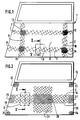
- FIG. 1 A first embodiment of a structural element according to the invention is shown in Figure 1.
- This element 1 here constitutes the outer metal part of a car door.
- the element 1 comprises a plate 2 made of a first metal or relatively light and soft alloy, for example aluminum.
- the plate 2 on the inner face of the plate 2, visible in elevation in FIG. 1, the plate 2 has a part 3 fixed on a predetermined limited area of said face.
- the part 3 has, in this example, the shape of a grid and is made of a second metal or alloy harder than that of the plate 2.
- this second metal is steel.
- the grid 3 consists of a perforated sheet.
- the grid 3 could also consist of interlaced wires.
- the part 3 is fixed to the plate 2 by cold stamping, so that the metal of the plate 2 penetrates into the openings of the part 3.
- the part 3 has been completely embedded in the plate 2, the metal of which has filled the openings 6 of the part 3.
- the part 3 no longer protrudes from the upper face of the plate 2.
- the grid 3 comprises four interlaced bands 7, 8, 9, 10, two bands 7 and 8 being horizontal and two bands 9 and 10 being vertical.
- the part 3 has a hollowed-out central part 11.
- the part 3 could also consist of a single-piece grid hollowed out in the central part.
- the parts 12, 13, 14, 15 of the grid 3, located at the intersections of the strips 7, 8, 9 and 10 therefore have a lower perforation density than the other parts of the grid 3.
- the surface of the openings is therefore reduced compared to to the other parts of the grid 3.
- the plate 2 can also undergo at least one stamping operation intended to give it a particular predetermined shape in relation to the function of the structural element. This operation can take place after fixing the part or simultaneously with this fixing as we will see later. This operation can still precede the fixing of the part.
- the part will advantageously have a shape adapted to that of the plate. For example, it will also have been stamped to give it a shape corresponding to that of the plate.
- FIG. 2 shows another embodiment of the invention, similar to that of FIG. 1.
- Element 16 also constitutes the external metal part of a car door and comprises a plate 2 identical to that of FIG. 1.
- the plate 2 has on its inner face a grid 17 similar to the grid 3.
- the grid 17 has the general shape of a cross fixed on an area located substantially in the center of the lower part of the plate 2.
- the grid 17 comprises a horizontal strip 18 extending from one edge 19 to the other 20 of the plate 2 and a vertical strip 21 perpendicular to the strip 18.
- the plate 2 has four other similar grids 22, 23, 24, 25 separated from each other. These four grids are fixed on the same face of the plate 2 as the grid 17, respectively at the four corners of the lower part of the face of the plate 2. Thus, these four grids are fixed on areas close to the edges of the plate 2, as well as the ends 26 and 27 of the horizontal strip 18.
- the part 28 of the cross corresponding to the intersection of the horizontal and vertical bands, the ends 26 and 27 and the parts 22, 23, 24, 25 have a density of perforation lower than the other parts of the grid 17.
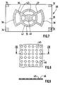
- FIG. 7 shows another embodiment of the invention.
- the element 60 consists of a rectangular aluminum plate 30. On one face thereof, four grids 31, 32, 33, 34 were fixed by cold stamping respectively to the four corners of the plate as well. a grid 35 over an area located substantially in the center of the plate.
- the grid 35 has the following form: it has two bands 36 and 37 arranged substantially along the diagonals of the rectangle. Two bands 38, 39 in an arc respectively join the ends of each band closest to each other.
- the grid has the shape of a disc 40 at the point of intersection of the strips 36 and 37. It has between the two strips 38 and 39 a circle 41 concentric with the disc 40 and distant from the latter.
- the grid 35 therefore has six recessed parts 42.
- the grids 31, 32, 33, 34 can be fixed to the four corners of the plate on the face opposite that which presents the grid 35, so that the grids are fixed on different faces of the plate 30.
- the grids 31, 32, 33, 34, 35 are made of harder metal than aluminum, for example steel.
- the parts anchored in the plate can alternatively consist of an perforated sheet 45, as in FIGS. 8 and 9.
- the sheet 45 is a sheet of hard metal, for example steel, in which openings or perforations 46 have been made, for example by means of a press.
- the perforation density on the sheet 45 can be varied as desired, by locally modifying the number and / or the dimensions of the perforations.
- FIG 12 there is shown a perforated sheet 60 whose perforation density is low in the central part due to the small diameter of the perforations 61 in this part.
- the openings shown in Figures 8 and 12 have a circular shape. However, the openings can have various shapes, for example square, hexagonal, etc.
- the invention also relates to a method for improving the properties of a structural element 1, in particular for a vehicle, comprising a plate 2 made of a relatively light and soft first metal or alloy.
- This process corresponds to the structural element according to the invention.
- the method comprises a step consisting in fixing in a predetermined limited area of one of the faces of the plate 2, a part 3, having the form of an openwork sheet or a grid made of a second metal. or a harder alloy than that of the plate, this fixing being effected by cold stamping, so that the metal of the plate 2 penetrates into the openings of the part 3.
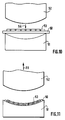
- Figures 10 and 11 show an advantageous mode of implementing the method according to the invention.
- the plate 50 to which it applies conventionally undergoes a stamping operation to give it a predetermined shape.
- the operation consists, for example here, in giving the initially planar plate 50 a curved shape.
- the fixing of the part 53 having the form of a grid or of a perforated sheet takes place during said die-stamping operation.
- the arrow 54 indicates the direction of movement of the movable part 52 towards the fixed part 51 for the purpose of stamping.
- the plate 50 and the part 53 are given the desired curvature and simultaneously the part 53 is pressed into the plate 50 to obtain the configuration described above.
- One of the main advantages of the structural element and of the method according to the invention is that the stamped part on the plate considerably increases the mechanical resistance of the latter and therefore of the structural element.
- the part can have a thickness that is substantially smaller than that of the plate.
- the anchoring of the part in the plate therefore does not significantly increase the weight of the element.
- the part is fixed on a predetermined limited area of the surface of the plate.
- This zone is determined in particular as a function of the mechanical stresses to which the structural element may be subjected during its use. Indeed, very often these constraints are particularly strong in certain places only of the element.
- the invention will advantageously be used in many fields where high mechanical strength and low weight are sought, such as land, air and sea vehicles or even the building industry.
Landscapes
- Engineering & Computer Science (AREA)
- Mechanical Engineering (AREA)
- Chemical & Material Sciences (AREA)
- Combustion & Propulsion (AREA)
- Transportation (AREA)
- Architecture (AREA)
- Structural Engineering (AREA)
- Textile Engineering (AREA)
- Body Structure For Vehicles (AREA)
- Building Environments (AREA)
Description
La présente invention vise un élément de structure, notamment pour véhicule, comprenant une plaque réalisée en un premier métal ou alliage relativement léger et mou. Elle vise aussi un procédé s'y rapportant et destiné à améliorer les propriétés d'un tel élément de structure.The present invention relates to a structural element, in particular for a vehicle, comprising a plate made of a relatively light and soft first metal or alloy. It also relates to a process relating thereto and intended to improve the properties of such a structural element.
La présente invention concerne notamment les véhicules terrestres, aériens ou maritimes. Le plus souvent, la carrosserie, le fuselage ou la coque de ces véhicules est constitué en grande partie de tôles minces assemblées entre elles.The present invention relates in particular to land, air or sea vehicles. Most often, the body, fuselage or hull of these vehicles is largely made of thin sheets assembled together.
Dans l'automobile par exemple, la carrosserie est notamment constituée de tôles en acier dont l'épaisseur est voisine d'un millimètre et qui sont serties, soudées ou rivetées.In the automobile industry, for example, the bodywork consists in particular of steel sheets the thickness of which is close to one millimeter and which are crimped, welded or riveted.
Toutefois, l'acier présente deux inconvénients majeurs: sa masse volumique est importante, ce qui le rend relativement lourd. De plus, il est très sensible à la corrosion. Bien entendu, l'acier peut être soumis à différents traitements de surface ou encore avoir une composition chimique augmentant sa résistance à la corrosion. Toutefois, le succès de ces méthodes anticorrosions est souvent partiel et la corrosion est en général inévitable à long terme.However, steel has two major drawbacks: its density is high, which makes it relatively heavy. In addition, it is very sensitive to corrosion. Of course, the steel can be subjected to various surface treatments or else have a chemical composition increasing its resistance to corrosion. However, the success of these anti-corrosion methods is often partial and corrosion is generally inevitable in the long term.
Il est connu par ailleurs de remplacer l'acier par de l'aluminium, notamment pour les véhicules aériens. En effet, l'aluminium est relativement léger et est très peu sensible à la corrosion. Cependant, la résistance mécanique de l'aluminium est faible, de sorte qu'il est relativement mou.It is also known to replace steel with aluminum, in particular for air vehicles. Indeed, aluminum is relatively light and is very little sensitive to corrosion. However, the mechanical strength of aluminum is low, so that it is relatively soft.
Pour donner à la plaque en aluminium une résistance mécanique comparable à la plaque en acier, il faut donc augmenter sensiblement son épaisseur, ce qui en retour, augmente le poids de la plaque et augmente son prix de revient.To give the aluminum plate a mechanical resistance comparable to the steel plate, it is therefore necessary to significantly increase its thickness, which in turn increases the weight of the plate and increases its cost price.
C'est pourquoi le but de l'invention est de pallier ces inconvénients et de réaliser des éléments de structure, présentant une résistance mécanique accrue pour une épaisseur faible, qui soient légers et peu coûteux.This is why the object of the invention is to overcome these drawbacks and produce structural elements, having increased mechanical strength for a small thickness, which are light and inexpensive.
L'invention vise donc un élément de structure, notamment pour véhicule comprenant une plaque réalisée en un premier métal ou alliage relativement léger et mou.The invention therefore relates to a structural element, in particular for a vehicle comprising a plate made of a relatively light and soft first metal or alloy.
Selon l'invention, l'élément de structure se caractérise en ce que la plaque présente sur une de ses faces dans une zone limitée prédéterminée de ladite face une pièce ayant la forme d'une feuille ajourée ou d'une grille réalisée en un second métal ou alliage plus dur que celui de la plaque, ladite pièce étant fixée à la plaque par matriçage à froid, de sorte que le métal de la plaque pénètre dans les ouvertures de la pièce.According to the invention, the structural element is characterized in that the plate has on one of its faces in a predetermined limited area of said face a part having the shape of an openwork sheet or a grid made in a second metal or alloy harder than that of the plate, said part being fixed to the plate by cold stamping, so that the metal of the plate penetrates into the openings of the part.
La pièce est fixée dans une zone limitée de la face de la plaque. Le poids total de l'élément de structure n'est donc pas augmenté sensiblement. Néanmoins, grâce à la résistance du métal dur, la pièce contribue à augmenter considérablement la résistance mécanique de l'élément de structure, principalement dans la zone de fixation.The part is fixed in a limited area of the face of the plate. The total weight of the structural element is therefore not increased significantly. However, thanks to the resistance of the hard metal, the part contributes to considerably increasing the mechanical resistance of the structural element, mainly in the fixing zone.
L'élément conserve donc en grande partie les avantages du premier métal, notamment sa légèreté et éventuellement son insensibilité à la corrosion tout en présentant une résistance mécanique accrue.The element therefore largely retains the advantages of the first metal, in particular its lightness and possibly its insensitivity to corrosion while exhibiting increased mechanical resistance.
L'invention permet donc de renforcer localement la résistance mécanique de l'élément de structure sans augmenter sensiblement son poids ni son coût total. De plus, il n'est pas nécessaire de donner à la pièce matricée une épaisseur importante. On pourra même souvent lui donner une épaisseur sensiblement plus faible que celle de la plaque.The invention therefore makes it possible to locally strengthen the mechanical strength of the structural element without significantly increasing its weight or its total cost. In addition, it is not necessary to give the stamped part a significant thickness. We can even often give it a thickness significantly smaller than that of the plate.
En outre, la fixation de la pièce comme indiqué, assure un ancrage simple et robuste de la pièce dans la plaque et une très bonne liaison mécanique entre les deux métaux. Au contraire, on sait qu'il est très délicat de souder de l'acier sur de l'aluminium, la résistance de la liaison ainsi réalisée étant souvent précaire. De même, l'assemblage de l'acier et de l'aluminium par rivetage n'assurerait pas une liaison mécanique continue des deux métaux et la présence des rivets génèrerait des surépaisseurs.In addition, fixing the part as indicated, ensures a simple and robust anchoring of the part in the plate and a very good mechanical connection between the two metals. On the contrary, we know that it is very delicate to weld steel on aluminum, the resistance of the the bond thus produced is often precarious. Likewise, the joining of steel and aluminum by riveting would not ensure a continuous mechanical connection of the two metals and the presence of the rivets would generate extra thicknesses.
Selon une version avantageuse de l'invention, au moins une partie de la pièce présente une densité de perforation inférieure à d'autres parties de la pièce.According to an advantageous version of the invention, at least one part of the part has a lower perforation density than other parts of the part.
Par densité de perforation, on désigne le rapport sur une partie de surface donnée de la pièce, entre la surface couverte par les perforations ou ouvertures et la surface totale de la partie. Ainsi, la densité de perforation est forte lorsque les perforations ou ouvertures sont nombreuses et/ou ont des dimensions importantes. La densité est faible dans les cas contraires.Perforation density denotes the ratio over a given part of the surface of the part, between the surface covered by the perforations or openings and the total surface of the part. Thus, the perforation density is high when the perforations or openings are numerous and / or have large dimensions. The density is low in contrary cases.
Les parties à faible densité de perforation donnent une résistance mécanique particulièrement forte aux parties de la plaque dans lesquelles elles sont ancrées, car la proportion d'acier en masse y est importante. Au contraire, les parties à faible densité de perforation augmentent modérément la résistance de l'élément de structure. On peut donc renforcer davantage la résistance des parties de la plaque qui seront soumises à des contraintes particulièrement élevées.The parts with a low perforation density give a particularly strong mechanical resistance to the parts of the plate in which they are anchored, because the proportion of steel by mass is important there. On the contrary, the parts with a low perforation density moderately increase the resistance of the structural element. It is therefore possible to further strengthen the resistance of the parts of the plate which will be subjected to particularly high stresses.
De plus, il est en général plus commode d'adapter la pièce aux contraintes subies par l'élément en variant localement la densité de perforation plutôt qu'en variant localement l'épaisseur de la pièce.In addition, it is generally more convenient to adapt the part to the stresses experienced by the element by locally varying the density of perforation rather than locally varying the thickness of the part.
Par commodité, l'expression "densité de perforation" sera utilisée y compris lorsque les ouvertures de la pièce ne résultent pas d'une opération de perforation, par exemple dans le cas d'une grille constituée de fils entrelacésFor convenience, the expression "perforation density" will be used even when the openings of the part do not result from a perforation operation, for example in the case of a grid made up of interlaced wires.
Selon une version préférée de l'invention, le premier métal est de l'aluminium et le second métal est de l'acier.According to a preferred version of the invention, the first metal is aluminum and the second metal is steel.
Selon une autre version avantageuse, la plaque présente au moins deux desdites pièces, ces deux pièces étant séparées l'une de l'autre.According to another advantageous version, the plate has at least two of said parts, these two parts being separated from one another.
L'invention vise également un procédé pour améliorer les propriétés d'un élément de structure, notamment pour véhicule, comprenant une plaque réalisée en un premier métal ou alliage relativement léger et mou.The invention also relates to a method for improving the properties of a structural element, in particular for a vehicle, comprising a plate made of a first metal or alloy which is relatively light and soft.
Selon l'invention, ce procédé comprend une étape consistant à fixer dans une zone limitée prédéterminée d'une des faces de la plaque une pièce ayant la forme d'une feuille ajourée ou d'une grille réalisée en un second métal en alliage plus dur que celui de la plaque, cette fixation étant effectuée par matriçage à froid, de sorte que le métal de la plaque pénètre dans les ouvertures de la pièce.According to the invention, this method comprises a step consisting in fixing in a predetermined limited area of one of the faces of the plate a part having the form of an openwork sheet or a grid made of a second metal of harder alloy than that of the plate, this fixing being effected by cold stamping, so that the metal of the plate penetrates into the openings of the part.
Les avantages de ce procédé correspondent à ceux précités de l'élément de structure selon l'invention.The advantages of this method correspond to those mentioned above of the structural element according to the invention.
Selon une version avantageuse, si la plaque subit une opération de matriçage pour lui donner une forme prédéterminée, la fixation de la pièce a lieu durant ladite opération de matriçage.According to an advantageous version, if the plate undergoes a stamping operation to give it a predetermined shape, the fixing of the part takes place during said stamping operation.
D'autres caractéristiques et avantages de l'invention apparaîtront encore dans la description qui va suivre de plusieurs modes de réalisation de l'invention. Aux dessins annexés:
- la figure 1 est une vue en élévation d'un élément de structure selon l'invention;
- la figure 2 est une vue en élévation d'un autre élément de structure selon l'invention;
- la figure 3 est une vue du détail D des grilles représentées sur les figures 1 et 2;
- la figure 4 est une vue en coupe selon le plan IV-IV de la figure 3;
- la figure 5 est une vue en coupe suivant le plan V-V du détail D des figures 1 et 2;
- la figure 6 est une variante de réalisation du dispositif de la figure 5;
- la figure 7 est une vue en élévation d'un autre élément de structure selon l'invention;
- la figure 8 est une vue en élévation d'une variante de réalisation de la pièce de la figure 3;
- la figure 9 est une vue en coupe suivant le plan IX-IX de la figure 8;
- les figures 10 et 11 sont des vues en élévation d'un mode de mise en oeuvre du procédé selon l'invention.
- la figure 12 est une variante de réalisation de la pièce de la figure 8.
- Figure 1 is an elevational view of a structural element according to the invention;
- Figure 2 is an elevational view of another structural element according to the invention;
- Figure 3 is a detail view D of the grids shown in Figures 1 and 2;
- Figure 4 is a sectional view along the plane IV-IV of Figure 3;
- Figure 5 is a sectional view along the plane VV of detail D of Figures 1 and 2;
- Figure 6 is an alternative embodiment of the device of Figure 5;
- Figure 7 is an elevational view of another structural element according to the invention;
- Figure 8 is an elevational view of an alternative embodiment of the part of Figure 3;
- Figure 9 is a sectional view along the plane IX-IX of Figure 8;
- Figures 10 and 11 are elevational views of an embodiment of the method according to the invention.
- FIG. 12 is an alternative embodiment of the part of FIG. 8.
Un premier mode de réalisation d'un élément de structure conforme à l'invention est présenté sur la figure 1. Cet élément 1 constitue ici la partie métallique extérieure d'une portière de voiture.A first embodiment of a structural element according to the invention is shown in Figure 1. This
L'élément 1 comprend une plaque 2 réalisée en un premier métal ou alliage relativement léger et mou, par exemple en l'aluminium.The
Selon l'invention, sur la face intérieure de la plaque 2, visible en élévation sur la figure 1, la plaque 2 présente une pièce 3 fixée sur une zone limitée prédéterminée de ladite face.According to the invention, on the inner face of the
Comme le montrent les figures 3 et 4 qui représentent un détail de la pièce 3, la pièce 3 a, dans cet exemple, la forme d'une grille et est réalisée en un second métal ou alliage plus dur que celui de la plaque 2. Dans le présent exemple, ce second métal est de l'acier.As shown in FIGS. 3 and 4 which represent a detail of the
Dans le présent exemple, la grille 3 est constituée d'une tôle perforée.In the present example, the
La grille 3 pourrait également être constituée de fils entrelacés.The
Selon l'invention, la pièce 3 est fixée à la plaque 2 par matriçage à froid, de sorte que le métal de la plaque 2 pénètre dans les ouvertures de la pièce 3.According to the invention, the
Sur la figure 5, on voit ainsi que le métal de la plaque 2 a flué à l'intérieur des ouvertures 6 de la pièce 3, de sorte que celle-ci est encastrée sur la moitié de son épaisseur dans la plaque 2.In FIG. 5, it can thus be seen that the metal of the
Dans la variante de réalisation présentée à la figure 6, la pièce 3 a été complètement encastrée dans la plaque 2 dont le métal a comblé les ouvertures 6 de la pièce 3. La pièce 3 ne dépasse plus de la face supérieure de la plaque 2.In the alternative embodiment presented in FIG. 6, the
Bien entendu, hormis ces deux exemples, différentes profondeurs d'encastrement de la pièce 3 dans la plaque 2 sont envisageables.Of course, apart from these two examples, different embedding depths of the
La grille 3 comprend quatre bandes 7, 8, 9, 10 entrecroisées, deux bandes 7 et 8 étant horizontales et deux bandes 9 et 10 étant verticales. Ainsi, la pièce 3 présente une partie centrale évidée 11. En variante, la pièce 3 pourrait aussi être consituée d'une grille d'un seul tenant évidée en partie centrale.The
Les parties 12, 13, 14, 15 de la grille 3, situées aux intersections des bandes 7, 8, 9 et 10 présentent donc une densité de perforation inférieure aux autres parties de la grille 3. La surface des ouvertures est donc réduite par rapport aux autres parties de la grille 3.The
Sur les figures 1, 2 et 7, la grille a été représentée de façon schématique. En particulier, on a représenté la différence de densité de perforation par des différences de densité de hachure. Il va de soi que ces hachures ne représentent pas exactement les fils de la grille.In Figures 1, 2 and 7, the grid has been shown schematically. In particular, the difference in perforation density has been represented by differences in hatch density. It goes without saying that these hatches do not exactly represent the wires of the grid.
Dans le cas d'une grille constituée de fils entrelacés, on peut également réduire la densité de perforation de certaines zones en réduisant localement la maille des entrelacements, c'est-à-dire en augmentant localement le nombre de fils.In the case of a grid made up of interlaced wires, it is also possible to reduce the perforation density of certain zones by locally reducing the mesh of the interleaves, that is to say by locally increasing the number of wires.
La plaque 2 peut par ailleurs subir au moins une opération d'emboutissage destinée à lui donner une forme particulière prédéterminée en rapport avec la fonction de l'élément de structure. Cette opération peut avoir lieu après fixation de la pièce ou simultanément à cette fixation comme on le verra plus loin. Cette opération peut encore précéder la fixation de la pièce. Dans ce cas, la pièce aura avantageusement une forme adaptée à celle de la plaque. Elle aura par exemple été également emboutie pour lui donner une forme correspondant à celle de la plaque.The
La figure 2 présente un autre mode de réalisation de l'invention, analogue à celui de la figure 1.FIG. 2 shows another embodiment of the invention, similar to that of FIG. 1.
L'élément 16 constitue également la partie métallique extérieure d'une portière de voiture et comprend une plaque 2 identique à celle de la figure 1.
La plaque 2 présente sur sa face intérieure une grille 17 analogue à la grille 3.The
La grille 17 a la forme générale d'une croix fixée sur une zone située sensiblement au centre de la partie inférieure de la plaque 2. La grille 17 comprend une bande horizontale 18 s'étendant d'un bord 19 à l'autre 20 de la plaque 2 et une bande verticale 21 perpendiculaire à la bande 18.The
En plus de la grille 17, la plaque 2 présente quatre autres grilles analogues 22, 23, 24, 25 séparées les unes des autres. Ces quatre grilles sont fixées sur la même face de la plaque 2 que la grille 17, respectivement aux quatre coins de la partie inférieure de la face de la plaque 2. Ainsi, ces quatre grilles sont fixées sur des zones voisines des bords de la plaque 2, de même que les extrémités 26 et 27 de la bande horizontale 18.In addition to the
La partie 28 de la croix correspondant à l'intersection des bandes horizontale et verticale, les extrémités 26 et 27 et les parties 22, 23, 24, 25 présentent une densité de perforation inférieure aux autres parties de la grille 17.The
La figure 7 présente un autre mode de réalisation de l'invention. L'élément 60 est constitué d'une plaque 30 rectangulaire en aluminium. Sur une face de celle-ci ont été fixées par matriçage à froid quatre grilles 31, 32, 33, 34 respectivement aux quatre coins de la plaque ainsi qu'une grille 35 sur une zone située sensiblement au centre de la plaque.Figure 7 shows another embodiment of the invention. The
La grille 35 a la forme suivante: elle présente deux bandes 36 et 37 disposées sensiblement suivant les diagonales du rectangle. Deux bandes 38, 39 en arc de cercle joignent respectivement les extrémités de chaque bande les plus proches l'une de l'autre. La grille a la forme d'un disque 40 au point d'intersection des bandes 36 et 37. Elle présente entre les deux bandes 38 et 39 un cercle 41 concentrique au disque 40 et distant de celui-ci.The
La grille 35 présente donc six parties évidées 42.The
Alternativement, les grilles 31, 32, 33, 34 peuvent être fixées aux quatre coins de la plaque sur la face opposée à celle qui présente la grille 35, de sorte que les grilles sont fixées sur des faces différentes de la plaque 30.Alternatively, the
Les grilles 31, 32, 33, 34, 35 sont en métal plus dur que l'aluminium, par exemple en acier.The
Dans chacun des modes de réalisation précités, les pièces ancrées dans la plaque peuvent alternativement être constituées d'une feuille ajourée 45, comme sur les figures 8 et 9.In each of the abovementioned embodiments, the parts anchored in the plate can alternatively consist of an
La feuille 45 est une feuille de métal dur, par exemple d'acier, dans laquelle ont été pratiquées des ouvertures ou perforations 46, par exemple au moyen d'une presse.The
Comme pour la grille, on peut varier à volonté la densité de perforation sur la feuille 45, en modifiant localement le nombre et/ou les dimensions des perforations.As for the grid, the perforation density on the
Par exemple, sur la figure 12, on a représenté une feuille perforée 60 dont la densité de perforation est faible en partie centrale en raison du faible diamètre des perforations 61 dans cette partie.For example, in Figure 12, there is shown a
Les ouvertures représentées sur les figures 8 et 12 ont une forme circulaire. Cependant, les ouvertures peuvent avoir des formes variées, par exemple carrées, hexagonales, etc.The openings shown in Figures 8 and 12 have a circular shape. However, the openings can have various shapes, for example square, hexagonal, etc.
En référence à la figure 1 notamment, l'invention vise également un procédé pour améliorer les propriétés d'un élément de structure 1, notamment pour véhicule, comprenant une plaque 2 réalisée en un premier métal ou alliage relativement léger et mou.With reference to FIG. 1 in particular, the invention also relates to a method for improving the properties of a
Ce procédé correspond à l'élément de structure selon l'invention.This process corresponds to the structural element according to the invention.
Selon l'invention, le procédé comprend une étape consistant à fixer dans une zone limitée prédéterminée d'une des faces de la plaque 2, une pièce 3, ayant la forme d'une feuille ajourée ou d'une grille réalisée en un second métal ou alliage plus dur que celui de la plaque, cette fixation étant effectuée par matriçage à froid, de sorte que le métal de la plaque 2 pénètre dans les ouvertures de la pièce 3.According to the invention, the method comprises a step consisting in fixing in a predetermined limited area of one of the faces of the
Les caractéristiques précitées de l'élément de structure selon l'invention, sont valables également pour le procédé selon l'invention.The aforementioned characteristics of the structural element according to the invention are also valid for the method according to the invention.
Les figures 10 et 11 présentent un mode avantageux de mise en oeuvre du procédé selon l'invention. La plaque 50 auquel il s'applique subit classiquement une opération de matriçage pour lui donner une forme prédéterminée.Figures 10 and 11 show an advantageous mode of implementing the method according to the invention. The
On a représenté schématiquement en 51 la partie fixe de la presse utilisée pour cette opération et en 52 la partie mobile de la presse. L'opération consiste par exemple ici, à donner à la plaque 50 initialement plane une forme courbe.There is shown schematically at 51 the fixed part of the press used for this operation and at 52 the mobile part of the press. The operation consists, for example here, in giving the initially planar plate 50 a curved shape.
Dans le présent mode de mise en oeuvre du procédé selon l'invention, la fixation de la pièce 53 ayant la forme d'une grille ou d'une feuille ajourée a lieu durant ladite opération de matriçage.In the present embodiment of the method according to the invention, the fixing of the
Ainsi, sur la figure 10, on a disposé la pièce 53 sur la plaque 50, elle-même disposée sur la partie fixe 51 de la presse. La pièce 53 et la plaque 50 ont alors une forme plane.Thus, in Figure 10, we have arranged the
La flèche 54 indique la direction du mouvement de la partie mobile 52 vers la partie fixe 51 en vue du matriçage. Durant le matriçage, on donne à la plaque 50 ainsi qu'à la pièce 53 la courbure désirée et simultanément on enfonce la pièce 53 dans la plaque 50 pour obtenir la configuration précédemment décrite.The
Le résultat de cette opération est représenté sur la figure 11, la flèche 55 indiquant le mouvement ascendant de la partie 52 qui s'éloigne après le matriçage.The result of this operation is shown in FIG. 11, the
L'un des principaux avantages de l'élément de structure et du procédé selon l'invention est que la pièce matricée sur la plaque augmente considérablement la résistance mécanique de celle-ci et donc de l'élément de structure.One of the main advantages of the structural element and of the method according to the invention is that the stamped part on the plate considerably increases the mechanical resistance of the latter and therefore of the structural element.
Cependant, la pièce peut avoir une épaisseur sensiblement plus faible que celle de la plaque. L'ancrage de la pièce dans la plaque n'augmente donc pas le poids de l'élément de façon importante.However, the part can have a thickness that is substantially smaller than that of the plate. The anchoring of the part in the plate therefore does not significantly increase the weight of the element.
La pièce est fixée sur une zone limitée prédéterminée de la surface de la plaque. Cette zone est déterminée notamment en fonction des contraintes mécaniques auxquelles pourra être soumis l'élément de structure durant son utilisation. En effet, très souvent ces contraintes sont particulièrement fortes en certains endroits seulement de l'élément.The part is fixed on a predetermined limited area of the surface of the plate. This zone is determined in particular as a function of the mechanical stresses to which the structural element may be subjected during its use. Indeed, very often these constraints are particularly strong in certain places only of the element.
Le choix de la forme de la pièce et conjointement de la zone de la plaque à couvrir avec la pièce permettent de renforcer l'élément de structure dans les zones les plus soumises aux contraintes mécaniques, sans renforcer d'autres zones qui sont peu exposées aux contraintes.The choice of the shape of the part and jointly of the zone of the plate to be covered with the part make it possible to reinforce the structural element in the zones most subjected to mechanical stresses, without reinforcing other zones which are little exposed to constraints.
Ainsi, dans l'exemple de la figure 1, on a désiré renforcer l'ensemble de la partie inférieure de la portière sans renforcer ses coins ni sa partie centrale. Au contraire, dans l'exemple de la figure 2, on a renforcé particulièrement les coins, les bords verticaux et le centre de la portière. La figure 7 donne un exemple de renfort de toute la partie centrale de la plaque et de ses coins.Thus, in the example of Figure 1, it was desired to strengthen the assembly of the lower part of the door without strengthening its corners or its central part. On the contrary, in the example of FIG. 2, the corners, the vertical edges and the center of the door have been particularly reinforced. Figure 7 gives an example of reinforcement of the entire central part of the plate and its corners.
A cet avantage, s'ajoute la possibilité de fixer plusieurs pièces séparées à la même plaque ou encore de varier la densité de perforation. Cette dernière caractéristique permet d'optimiser particulièrement le renfort de la plaque sans augmenter inutilement le poids de l'élément, en adaptant au plus près la densité de perforation aux contraintes exactes prévues dans les zones prédéterminées de l'élément.To this advantage, there is the possibility of attaching several separate pieces to the same plate or alternatively of varying the perforation density. This last characteristic makes it possible to optimize particularly the reinforcement of the plate without unnecessarily increasing the weight of the element, by adapting as closely as possible the density of perforation to the exact stresses provided for in the predetermined zones of the element.
L'invention sera avantageusement utilisée dans de nombreux domaines où une résistance mécanique importante et un poids faible sont recherchés tels que les véhicules terrestres, aériens et maritimes ou encore le bâtiment.The invention will advantageously be used in many fields where high mechanical strength and low weight are sought, such as land, air and sea vehicles or even the building industry.
Bien entendu, on pourra apporter de nombreuses améliorations et modifications à l'invention sans sortir du cadre de celle-ci.Of course, many improvements and modifications to the invention can be made without departing from the scope thereof.
Claims (10)
- A structural element (1; 16; 60), more particularly for a vehicle, comprising a plate (2; 30) made of a first relatively light and soft metal or alloy, characterised in that the plate (2; 30) has, on one of its surfaces, in a predetermined limited zone of said surface, a part (3; 17; 35) in the form of a perforate sheet (45) or grid (3) made from a second metal or alloy harder than that of the plate (2; 30), the said part (3; 17, 22, 23, 24, 25; 31, 32, 33, 34, 35) being fixed to the plate (2; 30) by cold die-stamping so that the metal of the plate (2; 30) penetrates into the apertures (6; 46) of the part (3; 17, 22, 23, 24, 25; 31, 32, 33, 34, 35).
- An element according to claim 1, characterised in that at least one portion (12, 13, 14, 15; 22, 23, 24, 25, 26, 27, 28) of the part (3; 17) has a perforation density less than other portions of the part.
- An element according to any of claims 1 or 2, characterised in that the part has at least one recessed portion (11; 42).
- An element according to any one of claims 1 to 3, characterised in that the plate (2; 30) has at least two of the said parts, said parts being fixed on the same surface of the plate (2; 30).
- An element according to any one of claims 1 to 3, characterised in that the plate (2; 30) has at least two of said parts, said parts being fixed on different surfaces of the plate.
- An element according to any one of claims 1 to 5, characterised in that the first metal is aluminium.
- An element according to any one of claims 1 to 6, characterised in that the second metal is steel.
- A method of improving the properties of a structural element (1; 16; 60), more particularly for a vehicle, comprising a plate (2; 30; 50) made of a first relatively light and soft metal or alloy, characterised in that it comprises a step wherein a part (3; 17, 22, 23, 24, 25; 31, 32, 33, 34, 35; 53) in the form of a perforate sheet (45) or a grid (3) made of a second metal or alloy harder than that of the plate (2; 30; 50) is fixed in a predetermined limited zone of one of the surfaces of the plate (2; 30; 50), said fixing being effected by cold die-stamping so that the metal of the plate (2; 30; 50) penetrates into the apertures (6; 46) of the part.
- A method according to claim 8, the plate (50) undergoing a die-stamping operation to give it a predetermined shape, characterised in that fixing of the part (53) takes place during the said die-stamping operation.
- A method according to claim 8 or 9, characterised in that at least two of the said parts are fixed on the plate, said parts being separated from one another.
Applications Claiming Priority (2)
| Application Number | Priority Date | Filing Date | Title |
|---|---|---|---|
| FR9308353 | 1993-07-07 | ||
| FR9308353A FR2707234B1 (en) | 1993-07-07 | 1993-07-07 | Structural element, in particular for a vehicle, comprising a relatively light and soft metal plate, and method relating thereto. |
Publications (2)
| Publication Number | Publication Date |
|---|---|
| EP0633182A1 EP0633182A1 (en) | 1995-01-11 |
| EP0633182B1 true EP0633182B1 (en) | 1997-01-08 |
Family
ID=9449022
Family Applications (1)
| Application Number | Title | Priority Date | Filing Date |
|---|---|---|---|
| EP19940401551 Expired - Lifetime EP0633182B1 (en) | 1993-07-07 | 1994-07-06 | Structural element, especially for a vehicle, comprising a relatively light and soft metal sheet, method for making it |
Country Status (4)
| Country | Link |
|---|---|
| EP (1) | EP0633182B1 (en) |
| DE (2) | DE69401390T2 (en) |
| ES (1) | ES2070802T1 (en) |
| FR (1) | FR2707234B1 (en) |
Cited By (3)
| Publication number | Priority date | Publication date | Assignee | Title |
|---|---|---|---|---|
| EP0882639A2 (en) | 1997-06-02 | 1998-12-09 | Volkswagen Aktiengesellschaft | Component for bodywork construction of motor vehicles and its method of manufacuture |
| US6220653B1 (en) | 1998-08-17 | 2001-04-24 | Volkswagen Ag | Body component arrangement for a motor vehicle |
| CN102310832A (en) * | 2010-06-28 | 2012-01-11 | 罗伯特·博世有限公司 | The vehicle structure that is used for vehicle |
Families Citing this family (6)
| Publication number | Priority date | Publication date | Assignee | Title |
|---|---|---|---|---|
| DE4437773C1 (en) * | 1994-10-24 | 1995-10-26 | Daimler Benz Ag | Instrument panel with an integrated, hinged gas bag cover |
| GB0107792D0 (en) * | 2001-03-28 | 2001-05-16 | Snow Jeremy A R | A vehicle body element |
| DE10254027B4 (en) * | 2002-11-20 | 2011-06-16 | Bayerische Motoren Werke Aktiengesellschaft | Motor vehicle with a side wall |
| US20120056445A1 (en) * | 2010-09-03 | 2012-03-08 | Ford Global Technologies, Llc | Body Panel and Reinforcement Assembly |
| DE102013012269A1 (en) * | 2013-07-24 | 2015-01-29 | GM Global Technology Operations LLC (n. d. Gesetzen des Staates Delaware) | Line-reinforced motor vehicle sheet metal, in particular body panel, and method for producing a line-reinforced motor vehicle sheet |
| DE102014018409A1 (en) | 2014-12-11 | 2016-06-16 | GM Global Technology Operations LLC (n. d. Ges. d. Staates Delaware) | Sheet metal and method for its production |
Family Cites Families (4)
| Publication number | Priority date | Publication date | Assignee | Title |
|---|---|---|---|---|
| FR664251A (en) * | 1927-11-08 | 1929-08-31 | Material composed of perforated metal sheets and sheets of thermoplastic material and articles made using this composite material | |
| US2237623A (en) * | 1935-01-31 | 1941-04-08 | Budd Edward G Mfg Co | Laminated sheet and stamped metal panel |
| JPS56153137A (en) * | 1980-04-28 | 1981-11-27 | Yokohama Rubber Co Ltd:The | Vibration damping and reinforcing method of thin plate component |
| DE4103036A1 (en) * | 1991-02-01 | 1992-08-06 | Bayerische Motoren Werke Ag | MOLDED VEHICLE COMPONENT |
-
1993
- 1993-07-07 FR FR9308353A patent/FR2707234B1/en not_active Expired - Fee Related
-
1994
- 1994-07-06 EP EP19940401551 patent/EP0633182B1/en not_active Expired - Lifetime
- 1994-07-06 DE DE1994601390 patent/DE69401390T2/en not_active Expired - Fee Related
- 1994-07-06 ES ES94401551T patent/ES2070802T1/en active Pending
- 1994-07-06 DE DE1994401551 patent/DE633182T1/en active Pending
Cited By (3)
| Publication number | Priority date | Publication date | Assignee | Title |
|---|---|---|---|---|
| EP0882639A2 (en) | 1997-06-02 | 1998-12-09 | Volkswagen Aktiengesellschaft | Component for bodywork construction of motor vehicles and its method of manufacuture |
| US6220653B1 (en) | 1998-08-17 | 2001-04-24 | Volkswagen Ag | Body component arrangement for a motor vehicle |
| CN102310832A (en) * | 2010-06-28 | 2012-01-11 | 罗伯特·博世有限公司 | The vehicle structure that is used for vehicle |
Also Published As
| Publication number | Publication date |
|---|---|
| FR2707234A1 (en) | 1995-01-13 |
| DE69401390T2 (en) | 1997-08-07 |
| FR2707234B1 (en) | 1995-09-08 |
| DE633182T1 (en) | 1995-09-28 |
| ES2070802T1 (en) | 1995-06-16 |
| EP0633182A1 (en) | 1995-01-11 |
| DE69401390D1 (en) | 1997-02-20 |
Similar Documents
| Publication | Publication Date | Title |
|---|---|---|
| EP0633182B1 (en) | Structural element, especially for a vehicle, comprising a relatively light and soft metal sheet, method for making it | |
| EP0687432B1 (en) | Seat-frame element, article using said element and its application especially to vehicle seats | |
| EP1109702B1 (en) | Bumper beam for motor vehicles | |
| WO2003047882A1 (en) | Motor vehicle wheel disc, in particular for private passenger vehicle | |
| FR2724882A1 (en) | Tubular frame for vehicle seat | |
| EP1517805B1 (en) | Suspension arm and method for making same | |
| FR2863673A1 (en) | DEVICE FOR ASSEMBLING BY SEPARATING MULTIPLE ELEMENTS AND METHOD FOR ASSEMBLING PANELS, IN PARTICULAR AIRCRAFT FUSELAGE USING THE SAME | |
| EP2091805B1 (en) | Central pillar structure for automotive vehicle | |
| EP0962742B1 (en) | Cutting device for non-metallic parts by means of a pyrotechnically expanding tube | |
| EP1638726B1 (en) | Means for assembling parts, comprising at least one welding cord created by transparency | |
| EP1567405B1 (en) | Motor vehicle body assembly particulartly the junction of body side upper rail and upper cross member supporting the windshield | |
| FR2841831A1 (en) | SUSPENSION FOR EXHAUST TUBING OF MOTOR VEHICLE AND VEHICLE EQUIPPED WITH SUCH SUSPENSION | |
| FR2853291A1 (en) | SUPPORT FOR A MOTOR VEHICLE BODY PART | |
| FR2879149A1 (en) | Console screen fixation system for motor vehicle hood, has rod, fixed to screen, whose end has pointed shape such that, under impact on screen, rod deforms and/or tears contact stud fixed to vehicle, so that rod is moved relative to stud | |
| FR2706366A1 (en) | Motor vehicle wheel | |
| FR2838376A1 (en) | Motor vehicle rear wheel suspension assembly comprises bracket with plate and flanges made at least partly from extruded metal or allow | |
| EP1675765B1 (en) | Center pillar structure for a motor vehicle | |
| FR2932764A1 (en) | Rear crosspiece for roof of motor vehicle, has longitudinal roof housing surface comprising rabbet and indentations provided at different heights for blocking studs such that crosspiece houses roofs with curves or inclinations | |
| FR2916690A1 (en) | Windscreen joint for motor vehicle, has pins provided at free end of arms with respect to windscreen or shrouded tail rotor, where arms are extended in space between windscreen and shrouded tail rotor | |
| EP1589163B1 (en) | Anchor for tilting and lifting a panel of hardenable material, in particular concrete | |
| EP1609699B1 (en) | Car roof and car provided with such a roof | |
| FR3106297A1 (en) | Laminated glazing for a motor vehicle, in particular a side glazing for a vehicle door | |
| WO2005030514A2 (en) | Sliding roof assembly for a motor vehicle and method for producing said assembly | |
| FR3139783A1 (en) | rear sill extension for motor vehicle | |
| EP0289397A1 (en) | Bumper for motor vehicle and vehicle equipped with such a bumper |
Legal Events
| Date | Code | Title | Description |
|---|---|---|---|
| PUAI | Public reference made under article 153(3) epc to a published international application that has entered the european phase |
Free format text: ORIGINAL CODE: 0009012 |
|
| 17P | Request for examination filed |
Effective date: 19940711 |
|
| AK | Designated contracting states |
Kind code of ref document: A1 Designated state(s): BE DE ES GB IT LU NL |
|
| REG | Reference to a national code |
Ref country code: ES Ref legal event code: BA2A Ref document number: 2070802 Country of ref document: ES Kind code of ref document: T1 |
|
| TCNL | Nl: translation of patent claims filed | ||
| ITCL | It: translation for ep claims filed |
Representative=s name: BARZANO' E ZANARDO MILANO S.P.A. |
|
| GBC | Gb: translation of claims filed (gb section 78(7)/1977) | ||
| DET | De: translation of patent claims | ||
| RAP1 | Party data changed (applicant data changed or rights of an application transferred) |
Owner name: SEB S.A. |
|
| GRAG | Despatch of communication of intention to grant |
Free format text: ORIGINAL CODE: EPIDOS AGRA |
|
| GRAH | Despatch of communication of intention to grant a patent |
Free format text: ORIGINAL CODE: EPIDOS IGRA |
|
| 17Q | First examination report despatched |
Effective date: 19960610 |
|
| GRAH | Despatch of communication of intention to grant a patent |
Free format text: ORIGINAL CODE: EPIDOS IGRA |
|
| GRAA | (expected) grant |
Free format text: ORIGINAL CODE: 0009210 |
|
| AK | Designated contracting states |
Kind code of ref document: B1 Designated state(s): BE DE ES GB IT LU NL |
|
| PG25 | Lapsed in a contracting state [announced via postgrant information from national office to epo] |
Ref country code: NL Free format text: LAPSE BECAUSE OF FAILURE TO SUBMIT A TRANSLATION OF THE DESCRIPTION OR TO PAY THE FEE WITHIN THE PRESCRIBED TIME-LIMIT Effective date: 19970108 Ref country code: GB Effective date: 19970108 |
|
| REF | Corresponds to: |
Ref document number: 69401390 Country of ref document: DE Date of ref document: 19970220 |
|
| ITF | It: translation for a ep patent filed |
Owner name: 0508;01TOFBARZANO'E ZANARDO S.P.A. |
|
| NLV1 | Nl: lapsed or annulled due to failure to fulfill the requirements of art. 29p and 29m of the patents act | ||
| GBV | Gb: ep patent (uk) treated as always having been void in accordance with gb section 77(7)/1977 [no translation filed] |
Effective date: 19970108 |
|
| PG25 | Lapsed in a contracting state [announced via postgrant information from national office to epo] |
Ref country code: ES Free format text: LAPSE BECAUSE OF FAILURE TO SUBMIT A TRANSLATION OF THE DESCRIPTION OR TO PAY THE FEE WITHIN THE PRESCRIBED TIME-LIMIT Effective date: 19970723 |
|
| PG25 | Lapsed in a contracting state [announced via postgrant information from national office to epo] |
Ref country code: LU Free format text: LAPSE BECAUSE OF NON-PAYMENT OF DUE FEES Effective date: 19970731 Ref country code: BE Free format text: LAPSE BECAUSE OF NON-PAYMENT OF DUE FEES Effective date: 19970731 |
|
| PLBE | No opposition filed within time limit |
Free format text: ORIGINAL CODE: 0009261 |
|
| STAA | Information on the status of an ep patent application or granted ep patent |
Free format text: STATUS: NO OPPOSITION FILED WITHIN TIME LIMIT |
|
| 26N | No opposition filed | ||
| BERE | Be: lapsed |
Owner name: S.A. SEB Effective date: 19970731 |
|
| PGFP | Annual fee paid to national office [announced via postgrant information from national office to epo] |
Ref country code: DE Payment date: 19980924 Year of fee payment: 5 |
|
| PG25 | Lapsed in a contracting state [announced via postgrant information from national office to epo] |
Ref country code: DE Free format text: LAPSE BECAUSE OF NON-PAYMENT OF DUE FEES Effective date: 20000503 |
|
| PG25 | Lapsed in a contracting state [announced via postgrant information from national office to epo] |
Ref country code: IT Free format text: LAPSE BECAUSE OF NON-PAYMENT OF DUE FEES;WARNING: LAPSES OF ITALIAN PATENTS WITH EFFECTIVE DATE BEFORE 2007 MAY HAVE OCCURRED AT ANY TIME BEFORE 2007. THE CORRECT EFFECTIVE DATE MAY BE DIFFERENT FROM THE ONE RECORDED. Effective date: 20050706 |