EP0633180A1 - Direction de sécurité pour véhicules à moteur - Google Patents
Direction de sécurité pour véhicules à moteur Download PDFInfo
- Publication number
- EP0633180A1 EP0633180A1 EP94109611A EP94109611A EP0633180A1 EP 0633180 A1 EP0633180 A1 EP 0633180A1 EP 94109611 A EP94109611 A EP 94109611A EP 94109611 A EP94109611 A EP 94109611A EP 0633180 A1 EP0633180 A1 EP 0633180A1
- Authority
- EP
- European Patent Office
- Prior art keywords
- elongated hole
- steering system
- safety
- steering wheel
- safety steering
- Prior art date
- Legal status (The legal status is an assumption and is not a legal conclusion. Google has not performed a legal analysis and makes no representation as to the accuracy of the status listed.)
- Granted
Links
Images

Classifications
-
- B—PERFORMING OPERATIONS; TRANSPORTING
- B62—LAND VEHICLES FOR TRAVELLING OTHERWISE THAN ON RAILS
- B62D—MOTOR VEHICLES; TRAILERS
- B62D1/00—Steering controls, i.e. means for initiating a change of direction of the vehicle
- B62D1/02—Steering controls, i.e. means for initiating a change of direction of the vehicle vehicle-mounted
- B62D1/16—Steering columns
- B62D1/18—Steering columns yieldable or adjustable, e.g. tiltable
- B62D1/19—Steering columns yieldable or adjustable, e.g. tiltable incorporating energy-absorbing arrangements, e.g. by being yieldable or collapsible
- B62D1/195—Yieldable supports for the steering column
-
- B—PERFORMING OPERATIONS; TRANSPORTING
- B62—LAND VEHICLES FOR TRAVELLING OTHERWISE THAN ON RAILS
- B62D—MOTOR VEHICLES; TRAILERS
- B62D1/00—Steering controls, i.e. means for initiating a change of direction of the vehicle
- B62D1/02—Steering controls, i.e. means for initiating a change of direction of the vehicle vehicle-mounted
- B62D1/16—Steering columns
- B62D1/18—Steering columns yieldable or adjustable, e.g. tiltable
Definitions
- the invention relates to a safety steering system for motor vehicles, in particular passenger cars, with the features of the preamble of patent claim 1.
- a deformation element connected to the steering column is arranged between the fastening of the steering column to the vehicle body and the steering column.
- This deformation element consists of a corrugated tension strip made of flat steel, which is arranged approximately perpendicular to the longitudinal direction of the steering shaft or the steering column. It extends between two fastening points for the steering column on the vehicle body located on both sides of the steering column, whereas the fastening of the deformation element itself is arranged approximately centrally in the steering column.
- the deformation element is screwed at its mounting points on the vehicle body between a flange of the steering column and the vehicle body, spacer sleeves being arranged between the vehicle body and the underside of the screw head.
- the present invention is based on this state of the art and aims to improve such a safety steering system in such a way that it corresponds as exactly as possible to the requirements of the safety regulations, namely that when the driver of the vehicle hits the steering wheel, it acts on the driver's chest Forces do not exceed a value required by law and that after the safety device has responded, the still effective forces show such a course that injuries can be avoided as far as possible.
- these are to be achieved by the invention Conditions are maintained unchanged during the life of the vehicle without the facility requiring maintenance. To solve this complex problem, those measures are proposed according to the invention which are the subject and content of the characterizing part of patent claim 1.
- the essential parts of the safety steering system here are the steering shaft 1, which is not further illustrated in its design, and which is rotatably mounted in the steering column 2 to be fastened to the vehicle body.
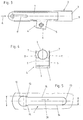
- This steering column 2 is shown in FIG. 3 in a side view and in FIG. 4 in a view (viewing direction arrow A in FIG. 3). It has a tube 3 for receiving the bearings and the steering shaft 1 and this tube 3 is received by a U-shaped bracket 4.
- This U-shaped bracket 4 has a web 6 connecting two parallel side cheeks 5.
- the upper sections of the two side cheeks 5 merge into elongated, U-shaped rails 7, the open sides of which face one another, the tube 3 lying between these rails 7 and is held by them.
- the diameter D of the arcuate boundary edge 12 facing away from the steering wheel is larger than the diameter d of the boundary edge 13 facing the steering wheel.
- the boundary edge 12 merges via a step-like shoulder 15 into the straight boundary edges 14, which here run parallel to one another over their lengths.
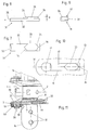
- angle brackets 16 are provided, the legs 17 of which project essentially laterally and have through openings 18 for receiving fastening screws.
- the vertical legs 19 of these angle brackets 16 are connected by fastening screws 20 to the rails 7 of the steering column 2, these fastening screws 20 passing through spacer sleeves 21 and the screws 20 together with the spacer sleeves 21 being each received by a bushing 22 made of easily deformable material, preferably made of plastic are.
- the inner diameter of this bushing 22 corresponds to the outer diameter of the spacer sleeve 21 and the outer diameter of the bushing 22 corresponds to the diameter D of the circular-arc-shaped boundary edge 12 of the elongated hole 11.
- the bushing 22 which is made of easily deformable material, preferably of plastic, has a laterally projecting collar 23 which is between the part 7 of the steering column 2 which has the slot recess 11 and the leg 19 of the angle bracket 16.
- the legs 19 of the angle bracket 16 can be extended beyond the bore for receiving the fastening means and these legs 19 thus extended can then be connected to one another by a crosspiece, so that the two angle brackets 16 form an integral, U-shaped component in view from the two cheeks of the legs 17 project laterally.
- the spacer sleeve 21 limits the effect of the clamping force of the tightened fastening screw 20 on the connection point, so that the angle bracket 16 or its leg 19 can be held pivotably about the axis of the fastening screw 20.
- a further U-shaped mounting bracket 24 is provided, the parallel cheeks 25 of which laterally projecting flanges 26 have receiving openings 27 which are designed as open slots against the steering wheel.
- substantially upright elongated slot recesses 28 are recessed.
- the bracket 4 of the steering column 2 lies, wherein the clamping bolt 10 passing through the push-through sleeve 8 also projects through the elongated hole recesses 28.
- the steering column is connected to the vehicle body with fastening screws, not shown here, which protrude into the through openings 18 of the legs 17 of the angle brackets 16 or into the receiving openings 27 of the flanges 26 of the mounting bracket 24.
- the clamping bolt 10 can be loosened or tightened so that the steering column can be pivoted about the axis of the fastening screws 20. If the handlebars are thrown against the steering wheel in the event of an accident, so that a sudden force acting from right to left (FIGS.
- An expedient embodiment of the invention now consists in arranging a deformation element 31 in the elongated hole recesses 11, as shown in FIGS. 7 to 9, in which case the shoulder 15 between the end boundary edge 12 and the straight boundary edges 14 of the elongated hole 11 are relative is made small, so that the major part of the deformation work is taken up by the deformation element 31 in the event of a crash.
- This deformation element 31 is made in one piece from a suitable plastic material and has an elongated base part 32 and a shoulder 33, which is molded onto an end section of the base part 32.
- the end contours 34 of the shoulder 33 end in tips, one contour being wedge-shaped and the other contour arcuate with a projecting pin 36.
- the height h of the shoulder 33 corresponds approximately to the wall thickness of the material in which the elongated hole 11 is formed .
- the axis length of the shoulder 33 corresponds to approximately half the length of the elongated hole 11.
- FIG. 10 The arrangement of this deformation element 31 in the elongated hole 11 is shown in FIG. 10 in view.
- One end face 35 of the deformation element 11 lies against the fastening means or the fastening screw 20, not shown here.
- the projecting pin 36 of the paragraph 33 is on the boundary edge 13 of the elongated hole 11.
- the base part 32 lies between the tube 3 and the rail 7 (FIG. 4).
- the fastening means or the fastening screw 20 presses in the direction of the arrow 30 (FIG. 10) onto the end face 35 of the deformation element 31 and pushes it to the right. This takes place under deformation of the pin 36, whereupon the curved contour of the shoulder 33 bears against the edge 13 of the elongated hole 11.
- the shoulder 33 is then sheared off from the base part 32, the fastening means or the fastening screw 20 then abutting the tip of the wedge-shaped contour and the shoulder 33 being deformed and destroyed as a whole.
- the fastening means or the fastening screw 20 By the choice of materials for this deformation element 31 and in particular also by the shape and contours of the end portions of the shoulder 33 and also by the configuration of the transition area, i.e. the paragraph 15 between the boundary edge 12 and the boundary edges 14 (see FIG. 5) of the Elongated hole 11, the force curve required by the automotive industry in the event of a crash can be achieved very precisely.
- the fastening screws received by them can also serve as a swivel axis for the steering wheel adjustment.
- the advantage sought according to the invention is also achieved if these elongated hole recesses 11 are provided essentially in horizontally lying structural parts.
- the collar 23 on the bush 22 prevents the parts to be connected (rail 7 and angle bracket 16) from abutting one another directly.
- washers and screw connections which are used in connection with the fastenings with which the steering column is fixed to the vehicle body.
- Spacer sleeves are also expediently used for these fastenings so that the holding force of the screw is not impaired by the tightening torque thereof, so that definable triggering forces are present.
- FIG. 11 shows a practical exemplary embodiment for the connection of steering column 2 and angle bracket 16 in longitudinal section, corresponding to the representation according to FIG. 6, in which FIG. 11 the same reference numbers have been used to designate the same parts as in the previously discussed embodiments.
- a rivet 37 is provided here with an axially extending bore 38.
- Plastic disks 39 penetrated by the rivet 37 lie on both sides of the leg 19 of the angle bracket 16.
- An outer metallic washer 40 serves as an abutment .
- the outer diameter of the shaft of the rivet 37 is slightly smaller than the diameter of the opening delimited by the boundary edge 12 of the elongated hole 11, so that the rivet 37 can be used without any special effort during assembly.
- the rivet punch not shown here, has a projecting and projecting mandrel, which penetrates into the bore 38 when riveting and thereby expands the cylindrical shaft of the rivet 37, so that the play provided for assembly is eliminated, so to speak, the shaft of the rivet 37 on the Wall of the opening receiving it fits snugly, so that the components mentioned are connected to each other without play.
Landscapes
- Engineering & Computer Science (AREA)
- Chemical & Material Sciences (AREA)
- Combustion & Propulsion (AREA)
- Transportation (AREA)
- Mechanical Engineering (AREA)
- Steering Controls (AREA)
Applications Claiming Priority (2)
| Application Number | Priority Date | Filing Date | Title |
|---|---|---|---|
| DE4322636A DE4322636C2 (de) | 1993-07-07 | 1993-07-07 | Sicherheitslenkung für Kraftfahrzeuge |
| DE4322636 | 1993-07-07 |
Publications (2)
| Publication Number | Publication Date |
|---|---|
| EP0633180A1 true EP0633180A1 (fr) | 1995-01-11 |
| EP0633180B1 EP0633180B1 (fr) | 1996-11-06 |
Family
ID=6492192
Family Applications (1)
| Application Number | Title | Priority Date | Filing Date |
|---|---|---|---|
| EP94109611A Expired - Lifetime EP0633180B1 (fr) | 1993-07-07 | 1994-06-22 | Direction de sécurité pour véhicules à moteur |
Country Status (6)
| Country | Link |
|---|---|
| US (1) | US5470107A (fr) |
| EP (1) | EP0633180B1 (fr) |
| JP (1) | JPH07144646A (fr) |
| KR (1) | KR960013904A (fr) |
| DE (1) | DE4322636C2 (fr) |
| ES (1) | ES2096379T3 (fr) |
Cited By (3)
| Publication number | Priority date | Publication date | Assignee | Title |
|---|---|---|---|---|
| FR2840869A1 (fr) * | 2002-06-17 | 2003-12-19 | Faurecia Ind | Ensemble de direction a absorption de choc, et vehicule automobile muni d'un tel ensemble |
| US7731235B2 (en) | 2006-05-02 | 2010-06-08 | Thyssenkrupp Presta Aktiengesellschaft | Steering column for a motor vehicle |
| WO2014086439A1 (fr) * | 2012-12-06 | 2014-06-12 | Thyssenkrupp Presta Aktiengesellschaft | Colonne de direction pour véhicule à moteur |
Families Citing this family (19)
| Publication number | Priority date | Publication date | Assignee | Title |
|---|---|---|---|---|
| DE19638316C1 (de) * | 1996-09-19 | 1998-02-19 | Lemfoerder Metallwaren Ag | Kraftfahrzeuglenksäulenbaueinheit |
| US5706704A (en) * | 1996-03-25 | 1998-01-13 | General Motors Corporation | Energy absorbing steering column for motor vehicle |
| JP3988200B2 (ja) * | 1997-03-14 | 2007-10-10 | 株式会社ジェイテクト | 衝撃吸収式ステアリング装置 |
| US6099038A (en) * | 1999-01-19 | 2000-08-08 | Daimlerchrysler Corporation | Upper and lower mounting bracket assembly for a steering column of an automotive vehicle |
| JP3468711B2 (ja) * | 1999-02-18 | 2003-11-17 | 株式会社山田製作所 | ステアリングコラムの衝撃吸収装置 |
| US6170873B1 (en) | 1999-03-29 | 2001-01-09 | Daimlerchrysler Corporation | Steering column mounting bracket with pull loops |
| JP3727004B2 (ja) * | 1999-09-10 | 2005-12-14 | 光洋精工株式会社 | 衝撃吸収式ステアリング装置及びこれに用いる取付部材 |
| JP2003019965A (ja) * | 2001-07-09 | 2003-01-21 | Aisin Seiki Co Ltd | 車両用ステアリング装置 |
| DE10141010A1 (de) * | 2001-08-21 | 2003-03-06 | Volkswagen Ag | Arretiervorrichtung mit einem Betätigungshebel für eine verstellbare Lenksäule |
| US6460427B1 (en) | 2002-01-28 | 2002-10-08 | Ford Global Technologies, Inc. | Adjustment linkage for tilting and telescoping a steering column assembly |
| US6863306B2 (en) * | 2002-11-08 | 2005-03-08 | Daimlerchrysler Corporation | Collapsing steering column with locking tilt mechanism |
| US20040093976A1 (en) * | 2002-11-14 | 2004-05-20 | Burke Gerald F. | Collapsible steering column |
| JP4331974B2 (ja) * | 2003-05-15 | 2009-09-16 | 三菱自動車工業株式会社 | ステアリングコラム支持装置 |
| US7469615B2 (en) * | 2004-02-19 | 2008-12-30 | Delphi Technologies, Inc. | Snap on lower bracket and bearing support |
| DE102004010791B4 (de) * | 2004-03-05 | 2008-10-02 | GM Global Technology Operations, Inc., Detroit | Lenksäule für ein Kraftfahrzeug als auch damit ausgerüstetes Kraftfahrzeug |
| US7661711B2 (en) * | 2006-10-26 | 2010-02-16 | Gm Global Technology Operations, Inc. | Steering column assembly with active energy absorption device |
| JP5272437B2 (ja) * | 2008-02-18 | 2013-08-28 | 日本精工株式会社 | ステアリング装置 |
| US8991865B2 (en) * | 2012-09-27 | 2015-03-31 | Mclaren Automotive Limited | Collapsible steering column |
| KR101469346B1 (ko) * | 2013-02-21 | 2014-12-04 | 주식회사 만도 | 차량용 조향 칼럼 |
Citations (7)
| Publication number | Priority date | Publication date | Assignee | Title |
|---|---|---|---|---|
| DE1911054A1 (de) * | 1969-03-05 | 1970-10-15 | Ford Werke Ag | Befestigung fuer Kraftfahrzeug-Sicherheitslenksaeulen |
| DE7303347U (de) * | 1973-01-30 | 1973-05-03 | Bayerische Motoren Werke Ag | Sicherheitslenkung fuer kraftfahrzeuge insbesondere personenkraftwagen |
| US3769851A (en) * | 1971-06-07 | 1973-11-06 | Peugeot | Energy absorbing device and safety steering column for a vehicle equipped with the device |
| DE2225128B2 (de) * | 1971-05-25 | 1978-09-28 | Toyota Jidosha Kogyo K.K., Toyota, Aichi (Japan) | Obere Abstützung einer steilgestellten Sicherheitslenksäule für Kraftfahrzeuge der Frontlenkerbauart |
| FR2392861A1 (fr) * | 1977-06-02 | 1978-12-29 | Alfa Romeo Spa | Direction enfoncable de securite pour vehicules automobiles |
| EP0479455A2 (fr) * | 1990-10-01 | 1992-04-08 | Ford Motor Company Limited | Ensemble de colonne de direction |
| EP0516966A1 (fr) * | 1991-06-07 | 1992-12-09 | Audi Ag | Direction de véhicule automobile avec une colonne de direction réglable en longueur portant un volant de direction |
Family Cites Families (9)
| Publication number | Priority date | Publication date | Assignee | Title |
|---|---|---|---|---|
| US3945662A (en) * | 1971-05-25 | 1976-03-23 | Toyota Jidosha Kogyo Kabushiki Kaisha | Energy absorbing steering assembly |
| JPS561277B2 (fr) * | 1973-07-04 | 1981-01-12 | ||
| IT1021290B (it) * | 1974-09-11 | 1978-01-30 | Alfa Romeo Alfasud | Dispositivo di sicurezza per si stema di sterzo di autoveicolo |
| GB2113164B (en) * | 1982-01-15 | 1985-07-17 | Ford Motor Co | Mounting for an adjustable steering column |
| DE3720320A1 (de) * | 1986-05-14 | 1988-12-29 | Porsche Ag | Lenksaeulenbefestigung fuer ein kraftfahrzeug mit einem deformationselement |
| DE3616246A1 (de) * | 1986-05-14 | 1987-11-19 | Porsche Ag | Lenksaeulenbefestigung fuer ein kraftfahrzeug |
| JPH01156170A (ja) * | 1987-12-14 | 1989-06-19 | Daihatsu Motor Co Ltd | 自動車のステアリングコラムチューブ |
| US4915412A (en) * | 1988-03-31 | 1990-04-10 | Nissan Motor Co., Ltd. | Tilting collapsible steering column |
| GB9010304D0 (en) * | 1990-05-08 | 1990-06-27 | Torrington Co | Mechanism for absorbing energy transmitted through a vehicle steering column |
-
1993
- 1993-07-07 DE DE4322636A patent/DE4322636C2/de not_active Expired - Fee Related
-
1994
- 1994-06-22 EP EP94109611A patent/EP0633180B1/fr not_active Expired - Lifetime
- 1994-06-22 ES ES94109611T patent/ES2096379T3/es not_active Expired - Lifetime
- 1994-07-06 JP JP6154995A patent/JPH07144646A/ja not_active Withdrawn
- 1994-07-07 US US08/271,596 patent/US5470107A/en not_active Expired - Lifetime
- 1994-07-07 KR KR1019940016367A patent/KR960013904A/ko active IP Right Grant
Patent Citations (7)
| Publication number | Priority date | Publication date | Assignee | Title |
|---|---|---|---|---|
| DE1911054A1 (de) * | 1969-03-05 | 1970-10-15 | Ford Werke Ag | Befestigung fuer Kraftfahrzeug-Sicherheitslenksaeulen |
| DE2225128B2 (de) * | 1971-05-25 | 1978-09-28 | Toyota Jidosha Kogyo K.K., Toyota, Aichi (Japan) | Obere Abstützung einer steilgestellten Sicherheitslenksäule für Kraftfahrzeuge der Frontlenkerbauart |
| US3769851A (en) * | 1971-06-07 | 1973-11-06 | Peugeot | Energy absorbing device and safety steering column for a vehicle equipped with the device |
| DE7303347U (de) * | 1973-01-30 | 1973-05-03 | Bayerische Motoren Werke Ag | Sicherheitslenkung fuer kraftfahrzeuge insbesondere personenkraftwagen |
| FR2392861A1 (fr) * | 1977-06-02 | 1978-12-29 | Alfa Romeo Spa | Direction enfoncable de securite pour vehicules automobiles |
| EP0479455A2 (fr) * | 1990-10-01 | 1992-04-08 | Ford Motor Company Limited | Ensemble de colonne de direction |
| EP0516966A1 (fr) * | 1991-06-07 | 1992-12-09 | Audi Ag | Direction de véhicule automobile avec une colonne de direction réglable en longueur portant un volant de direction |
Cited By (4)
| Publication number | Priority date | Publication date | Assignee | Title |
|---|---|---|---|---|
| FR2840869A1 (fr) * | 2002-06-17 | 2003-12-19 | Faurecia Ind | Ensemble de direction a absorption de choc, et vehicule automobile muni d'un tel ensemble |
| US7731235B2 (en) | 2006-05-02 | 2010-06-08 | Thyssenkrupp Presta Aktiengesellschaft | Steering column for a motor vehicle |
| WO2014086439A1 (fr) * | 2012-12-06 | 2014-06-12 | Thyssenkrupp Presta Aktiengesellschaft | Colonne de direction pour véhicule à moteur |
| US9540032B2 (en) | 2012-12-06 | 2017-01-10 | Thyssenkrupp Presta Aktiengesellschaft | Steering column for a motor vehicle |
Also Published As
| Publication number | Publication date |
|---|---|
| EP0633180B1 (fr) | 1996-11-06 |
| US5470107A (en) | 1995-11-28 |
| DE4322636C2 (de) | 2002-08-22 |
| JPH07144646A (ja) | 1995-06-06 |
| KR960013904A (ko) | 1996-05-22 |
| DE4322636A1 (de) | 1995-01-19 |
| ES2096379T3 (es) | 1997-03-01 |
Similar Documents
| Publication | Publication Date | Title |
|---|---|---|
| EP0633180B1 (fr) | Direction de sécurité pour véhicules à moteur | |
| EP1701861B1 (fr) | Mecanisme de commande d'un dispositif de reglage des sieges de vehicules automobiles | |
| EP0836981A1 (fr) | Dispositif de réglage de la longueur et de l'inclinaison d'une colonne de direction pour véhicules à moteur | |
| DE2521426A1 (de) | Sollbruchvorrichtung zur halterung eines pfostens | |
| EP0681943A1 (fr) | Dispositif de fixation | |
| DE19745016C2 (de) | Umlenkbeschlag für Sicherheitsgurte von Fahrzeugen, insbesondere Kraftfahrzeugen | |
| WO2002051669A1 (fr) | Dispositif pour le logement d'un levier de pedale dans un vehicule | |
| EP0702123A1 (fr) | Charnière de porte à arrêtoir de porte intégré pour portes de véhicules | |
| DE19735818C2 (de) | Befestigungsvorrichtung für eine Scheibenwischeranlage eines Kraftfahrzeuges | |
| EP0252232B1 (fr) | Dispositif d'arrêt pour une colonne de direction de véhicule automobile | |
| DE3116821A1 (de) | Scheibenwischeranlage fuer ein kraftfahrzeug, insbesondere personenkraftwagen | |
| DE19738803A1 (de) | Gehäuse für ein Gerät, insbesondere Sensor für Kraftfahrzeuge | |
| EP1213161A2 (fr) | Dispositif de traction de remorque | |
| DE10040270A1 (de) | Sicherheitseinrichtung im Pedalbereich für einen PKW | |
| WO2004058543A1 (fr) | Boitier amortisseur de chocs comprenant un element de maintien pour un systeme de refroidissement | |
| DE4201388A1 (de) | Unterfahrschutz fuer nutzfahrzeuge | |
| DE102005031594A1 (de) | Klemmvorrichtung für eine Lenksäule | |
| DE4434152C2 (de) | Spurstangenkopf-Auspreßvorrichtung | |
| DE4342402C2 (de) | Antriebs- und Riegelmechanismus für einen geradlinig ausfahrbaren Überrollbügel | |
| EP0785125A2 (fr) | Dispositif anti-rotation et antivol pour limiter l'extraction d'un support de selle ajustable hydrauliquement | |
| DE2852266A1 (de) | Kopfstuetze fuer kraftfahrzeugsitze | |
| DE3829929A1 (de) | Hoehenverstellvorrichtung fuer einen beschlag eines sicherheitsgurt-rueckhaltesystems in kraftfahrzeugen | |
| DE19906669C2 (de) | Vorrichtung zur Befestigung eines Fahrzeugsitzes | |
| DE19840426B4 (de) | Lenksäulenlagerung | |
| EP0831009A2 (fr) | Ensemble d'une colonne de direction de véhicule automobile |
Legal Events
| Date | Code | Title | Description |
|---|---|---|---|
| PUAI | Public reference made under article 153(3) epc to a published international application that has entered the european phase |
Free format text: ORIGINAL CODE: 0009012 |
|
| AK | Designated contracting states |
Kind code of ref document: A1 Designated state(s): ES FR GB IT SE |
|
| 17P | Request for examination filed |
Effective date: 19950315 |
|
| 17Q | First examination report despatched |
Effective date: 19950425 |
|
| GRAG | Despatch of communication of intention to grant |
Free format text: ORIGINAL CODE: EPIDOS AGRA |
|
| GRAH | Despatch of communication of intention to grant a patent |
Free format text: ORIGINAL CODE: EPIDOS IGRA |
|
| GRAH | Despatch of communication of intention to grant a patent |
Free format text: ORIGINAL CODE: EPIDOS IGRA |
|
| GRAA | (expected) grant |
Free format text: ORIGINAL CODE: 0009210 |
|
| STAA | Information on the status of an ep patent application or granted ep patent |
Free format text: STATUS: THE PATENT HAS BEEN GRANTED |
|
| AK | Designated contracting states |
Kind code of ref document: B1 Designated state(s): ES FR GB IT SE |
|
| ITF | It: translation for a ep patent filed |
Owner name: INTERPATENT ST.TECN. BREV. |
|
| REG | Reference to a national code |
Ref country code: ES Ref legal event code: FG2A Ref document number: 2096379 Country of ref document: ES Kind code of ref document: T3 |
|
| GBT | Gb: translation of ep patent filed (gb section 77(6)(a)/1977) |
Effective date: 19970211 |
|
| ET | Fr: translation filed | ||
| PLBE | No opposition filed within time limit |
Free format text: ORIGINAL CODE: 0009261 |
|
| 26N | No opposition filed | ||
| REG | Reference to a national code |
Ref country code: GB Ref legal event code: IF02 |
|
| PGFP | Annual fee paid to national office [announced via postgrant information from national office to epo] |
Ref country code: SE Payment date: 20090625 Year of fee payment: 16 Ref country code: IT Payment date: 20090617 Year of fee payment: 16 |
|
| PGFP | Annual fee paid to national office [announced via postgrant information from national office to epo] |
Ref country code: FR Payment date: 20090625 Year of fee payment: 16 Ref country code: ES Payment date: 20090630 Year of fee payment: 16 |
|
| PGFP | Annual fee paid to national office [announced via postgrant information from national office to epo] |
Ref country code: GB Payment date: 20090617 Year of fee payment: 16 |
|
| EUG | Se: european patent has lapsed | ||
| GBPC | Gb: european patent ceased through non-payment of renewal fee |
Effective date: 20100622 |
|
| REG | Reference to a national code |
Ref country code: FR Ref legal event code: ST Effective date: 20110228 |
|
| PG25 | Lapsed in a contracting state [announced via postgrant information from national office to epo] |
Ref country code: IT Free format text: LAPSE BECAUSE OF NON-PAYMENT OF DUE FEES Effective date: 20100622 |
|
| PG25 | Lapsed in a contracting state [announced via postgrant information from national office to epo] |
Ref country code: FR Free format text: LAPSE BECAUSE OF NON-PAYMENT OF DUE FEES Effective date: 20100630 |
|
| REG | Reference to a national code |
Ref country code: ES Ref legal event code: FD2A Effective date: 20110715 |
|
| PG25 | Lapsed in a contracting state [announced via postgrant information from national office to epo] |
Ref country code: ES Free format text: LAPSE BECAUSE OF NON-PAYMENT OF DUE FEES Effective date: 20110705 Ref country code: GB Free format text: LAPSE BECAUSE OF NON-PAYMENT OF DUE FEES Effective date: 20100622 |
|
| PG25 | Lapsed in a contracting state [announced via postgrant information from national office to epo] |
Ref country code: ES Free format text: LAPSE BECAUSE OF NON-PAYMENT OF DUE FEES Effective date: 20100623 |
|
| PG25 | Lapsed in a contracting state [announced via postgrant information from national office to epo] |
Ref country code: SE Free format text: LAPSE BECAUSE OF NON-PAYMENT OF DUE FEES Effective date: 20100623 |