EP0632567B1 - Verfahren und Vorrichtung zum automatischen Bilden von ausgerichteten Blechpaketen zur Herstellung von Ankern elektrischer Maschinen oder dergleichen - Google Patents
Verfahren und Vorrichtung zum automatischen Bilden von ausgerichteten Blechpaketen zur Herstellung von Ankern elektrischer Maschinen oder dergleichen Download PDFInfo
- Publication number
- EP0632567B1 EP0632567B1 EP94107753A EP94107753A EP0632567B1 EP 0632567 B1 EP0632567 B1 EP 0632567B1 EP 94107753 A EP94107753 A EP 94107753A EP 94107753 A EP94107753 A EP 94107753A EP 0632567 B1 EP0632567 B1 EP 0632567B1
- Authority
- EP
- European Patent Office
- Prior art keywords
- sheet
- stack
- pack
- magazine
- clamp
- Prior art date
- Legal status (The legal status is an assumption and is not a legal conclusion. Google has not performed a legal analysis and makes no representation as to the accuracy of the status listed.)
- Expired - Lifetime
Links
- 238000000034 method Methods 0.000 title claims description 22
- 238000004519 manufacturing process Methods 0.000 title claims description 7
- 239000002184 metal Substances 0.000 title claims description 5
- 230000005484 gravity Effects 0.000 claims description 10
- 238000000926 separation method Methods 0.000 claims description 9
- 230000002093 peripheral effect Effects 0.000 claims description 7
- 230000006835 compression Effects 0.000 claims description 6
- 238000007906 compression Methods 0.000 claims description 6
- 230000000903 blocking effect Effects 0.000 claims description 2
- 230000015572 biosynthetic process Effects 0.000 description 3
- 238000000137 annealing Methods 0.000 description 2
- 239000000314 lubricant Substances 0.000 description 2
- 239000000463 material Substances 0.000 description 2
- 230000005540 biological transmission Effects 0.000 description 1
- 230000001419 dependent effect Effects 0.000 description 1
- 230000000694 effects Effects 0.000 description 1
- 230000005489 elastic deformation Effects 0.000 description 1
- -1 oxides Substances 0.000 description 1
- 230000000284 resting effect Effects 0.000 description 1
- 239000000523 sample Substances 0.000 description 1
- 238000009966 trimming Methods 0.000 description 1
Images


Classifications
-
- H—ELECTRICITY
- H02—GENERATION; CONVERSION OR DISTRIBUTION OF ELECTRIC POWER
- H02K—DYNAMO-ELECTRIC MACHINES
- H02K15/00—Processes or apparatus specially adapted for manufacturing, assembling, maintaining or repairing of dynamo-electric machines
- H02K15/02—Processes or apparatus specially adapted for manufacturing, assembling, maintaining or repairing of dynamo-electric machines of stator or rotor bodies
-
- B—PERFORMING OPERATIONS; TRANSPORTING
- B21—MECHANICAL METAL-WORKING WITHOUT ESSENTIALLY REMOVING MATERIAL; PUNCHING METAL
- B21D—WORKING OR PROCESSING OF SHEET METAL OR METAL TUBES, RODS OR PROFILES WITHOUT ESSENTIALLY REMOVING MATERIAL; PUNCHING METAL
- B21D43/00—Feeding, positioning or storing devices combined with, or arranged in, or specially adapted for use in connection with, apparatus for working or processing sheet metal, metal tubes or metal profiles; Associations therewith of cutting devices
- B21D43/20—Storage arrangements; Piling or unpiling
- B21D43/22—Devices for piling sheets
-
- H—ELECTRICITY
- H01—ELECTRIC ELEMENTS
- H01F—MAGNETS; INDUCTANCES; TRANSFORMERS; SELECTION OF MATERIALS FOR THEIR MAGNETIC PROPERTIES
- H01F41/00—Apparatus or processes specially adapted for manufacturing or assembling magnets, inductances or transformers; Apparatus or processes specially adapted for manufacturing materials characterised by their magnetic properties
- H01F41/02—Apparatus or processes specially adapted for manufacturing or assembling magnets, inductances or transformers; Apparatus or processes specially adapted for manufacturing materials characterised by their magnetic properties for manufacturing cores, coils, or magnets
- H01F41/0206—Manufacturing of magnetic cores by mechanical means
- H01F41/0233—Manufacturing of magnetic circuits made from sheets
-
- Y—GENERAL TAGGING OF NEW TECHNOLOGICAL DEVELOPMENTS; GENERAL TAGGING OF CROSS-SECTIONAL TECHNOLOGIES SPANNING OVER SEVERAL SECTIONS OF THE IPC; TECHNICAL SUBJECTS COVERED BY FORMER USPC CROSS-REFERENCE ART COLLECTIONS [XRACs] AND DIGESTS
- Y10—TECHNICAL SUBJECTS COVERED BY FORMER USPC
- Y10S—TECHNICAL SUBJECTS COVERED BY FORMER USPC CROSS-REFERENCE ART COLLECTIONS [XRACs] AND DIGESTS
- Y10S414/00—Material or article handling
- Y10S414/10—Associated with forming or dispersing groups of intersupporting articles, e.g. stacking patterns
- Y10S414/102—Associated with forming or dispersing groups of intersupporting articles, e.g. stacking patterns including support for group
- Y10S414/103—Vertically shiftable
-
- Y—GENERAL TAGGING OF NEW TECHNOLOGICAL DEVELOPMENTS; GENERAL TAGGING OF CROSS-SECTIONAL TECHNOLOGIES SPANNING OVER SEVERAL SECTIONS OF THE IPC; TECHNICAL SUBJECTS COVERED BY FORMER USPC CROSS-REFERENCE ART COLLECTIONS [XRACs] AND DIGESTS
- Y10—TECHNICAL SUBJECTS COVERED BY FORMER USPC
- Y10S—TECHNICAL SUBJECTS COVERED BY FORMER USPC CROSS-REFERENCE ART COLLECTIONS [XRACs] AND DIGESTS
- Y10S414/00—Material or article handling
- Y10S414/10—Associated with forming or dispersing groups of intersupporting articles, e.g. stacking patterns
- Y10S414/114—Adjust to handle articles or groups of different sizes
-
- Y—GENERAL TAGGING OF NEW TECHNOLOGICAL DEVELOPMENTS; GENERAL TAGGING OF CROSS-SECTIONAL TECHNOLOGIES SPANNING OVER SEVERAL SECTIONS OF THE IPC; TECHNICAL SUBJECTS COVERED BY FORMER USPC CROSS-REFERENCE ART COLLECTIONS [XRACs] AND DIGESTS
- Y10—TECHNICAL SUBJECTS COVERED BY FORMER USPC
- Y10S—TECHNICAL SUBJECTS COVERED BY FORMER USPC CROSS-REFERENCE ART COLLECTIONS [XRACs] AND DIGESTS
- Y10S414/00—Material or article handling
- Y10S414/10—Associated with forming or dispersing groups of intersupporting articles, e.g. stacking patterns
- Y10S414/12—Associated with forming or dispersing groups of intersupporting articles, e.g. stacking patterns including means pressing against top or end of group
-
- Y—GENERAL TAGGING OF NEW TECHNOLOGICAL DEVELOPMENTS; GENERAL TAGGING OF CROSS-SECTIONAL TECHNOLOGIES SPANNING OVER SEVERAL SECTIONS OF THE IPC; TECHNICAL SUBJECTS COVERED BY FORMER USPC CROSS-REFERENCE ART COLLECTIONS [XRACs] AND DIGESTS
- Y10—TECHNICAL SUBJECTS COVERED BY FORMER USPC
- Y10T—TECHNICAL SUBJECTS COVERED BY FORMER US CLASSIFICATION
- Y10T29/00—Metal working
- Y10T29/49—Method of mechanical manufacture
- Y10T29/49002—Electrical device making
- Y10T29/49009—Dynamoelectric machine
- Y10T29/49012—Rotor
-
- Y—GENERAL TAGGING OF NEW TECHNOLOGICAL DEVELOPMENTS; GENERAL TAGGING OF CROSS-SECTIONAL TECHNOLOGIES SPANNING OVER SEVERAL SECTIONS OF THE IPC; TECHNICAL SUBJECTS COVERED BY FORMER USPC CROSS-REFERENCE ART COLLECTIONS [XRACs] AND DIGESTS
- Y10—TECHNICAL SUBJECTS COVERED BY FORMER USPC
- Y10T—TECHNICAL SUBJECTS COVERED BY FORMER US CLASSIFICATION
- Y10T29/00—Metal working
- Y10T29/49—Method of mechanical manufacture
- Y10T29/49002—Electrical device making
- Y10T29/4902—Electromagnet, transformer or inductor
- Y10T29/49075—Electromagnet, transformer or inductor including permanent magnet or core
- Y10T29/49078—Laminated
-
- Y—GENERAL TAGGING OF NEW TECHNOLOGICAL DEVELOPMENTS; GENERAL TAGGING OF CROSS-SECTIONAL TECHNOLOGIES SPANNING OVER SEVERAL SECTIONS OF THE IPC; TECHNICAL SUBJECTS COVERED BY FORMER USPC CROSS-REFERENCE ART COLLECTIONS [XRACs] AND DIGESTS
- Y10—TECHNICAL SUBJECTS COVERED BY FORMER USPC
- Y10T—TECHNICAL SUBJECTS COVERED BY FORMER US CLASSIFICATION
- Y10T29/00—Metal working
- Y10T29/53—Means to assemble or disassemble
- Y10T29/5313—Means to assemble electrical device
- Y10T29/53143—Motor or generator
-
- Y—GENERAL TAGGING OF NEW TECHNOLOGICAL DEVELOPMENTS; GENERAL TAGGING OF CROSS-SECTIONAL TECHNOLOGIES SPANNING OVER SEVERAL SECTIONS OF THE IPC; TECHNICAL SUBJECTS COVERED BY FORMER USPC CROSS-REFERENCE ART COLLECTIONS [XRACs] AND DIGESTS
- Y10—TECHNICAL SUBJECTS COVERED BY FORMER USPC
- Y10T—TECHNICAL SUBJECTS COVERED BY FORMER US CLASSIFICATION
- Y10T29/00—Metal working
- Y10T29/53—Means to assemble or disassemble
- Y10T29/5313—Means to assemble electrical device
- Y10T29/5317—Laminated device
Definitions
- the invention relates to a method for automatic forming of packs of trimmed metal sheets for the manufacture of armatures of electrical machinery or the like, through automatic precision proportioning of the sheet pack consisting of the collection and separation of a predefined number of sheets, corresponding to a predefined height of the pack itself, from a sheet stack, said method being carried out by means of a device which is provided with a vertical magazine for a sheet stack which is open at the bottom and the lower end of which is associated with a raisable and lowerable bottom for the collection of the sheet pack, according to the preamble of claim 1.
- This method is used for the manufacture of metal armatures, for instance, of stators and rotors for electric motors, trasformers, remote control switches etc. and is known from prior use in machines manufactured by the Applicant.
- the proportioning of the sheet pack to be separated from the sheet stack is made difficult by the fact that, for a predefined height of the sheet pack, no-one knows the number of sheets comprising it and thus no-one can determine the division line between the last upper sheet of the pack to separate and the lower sheet of the stack which constitutes the first lower sheet of the subsequent pack. This is due to the tolerances in the thickness of the plate from which individual sheets are trimmed. Owing to the tolerances of these plates, when the pack is separated from the overlying stack of sheets, the last upper sheet still belonging to the separated pack can still be held temporarily at the lower end of the overlying stack of sheets by means intended to block it in the magazine, being, for instance, engaged by said means only for a small portion of its thickness.
- the separated sheet pack is missing a sheet and thus undersized. Furthermore, the last sheet belonging to the separated pack and precariously held against the overlying stack can detach itself from the stack at any time and, falling in an uncontrolled manner, can damage and jam the device.
- the last sheet of the separated pack can be precariously held against the stack itself, because of a moderate sticking or adhesion effect due, for instance, to the presence of trimming lubricants, oxides, material annealing, or other similar causes.
- the purpose of the invention is to enhance a method and device for forming packs of sheets of the type described above which, by relatively simple and non-costly means, makes it possible effectively to avoid the above disadvantages, so as to attain maximum operating speed and maximum pack proportioning precision, thus avoiding interruptions in the productive cycle and possible damages to the device.
- the invention solves this problem with a method such as the one described above which includes the following phases for forming the sheet pack:
- the collection bottom is provided with guiding and centring means for the sheets which vertically extend from the upper side of the bottom itself towards the sheet stack, their length being such as to engage, in the raised position of the collection bottom against the stack, at least one lower sheet, preferably a number of lower sheets, of the sheet stack, so that, upon the first detachment lowering of the collection bottom, said guiding and centring means are still engaged at least in the last lower sheet of the stack, while detachment is followed by a second lowering of the collection bottom for disengagement of the guiding and centring means for the overlying sheet stack.
- the method in accordance with the invention provides for the accomplishment of said action, regardless of whether said phenomenon of precarious holding or adhesion of the last sheet of the pack to the sheet stack occurred or not, thus obtaining the advantage of avoiding further means for controlling the continuation of said event.
- the method and the device in accordance with the invention make it possible to obtain sheet packs proportioned in an extremely precise manner, thus preventing any sheet erroneously and precariously held on the bottom of the stack from detaching itself in an uncontrolled manner, causing an interruption in the production cycle or a jamming and/or damaging of the machine's operating parts.
- the sheet guiding and centring means control the fall of the sheet attached to the overlying pack which will thus be precisely aligned on the remaining part of the pack.
- the invention relates also to a device for carrying out the method, this device comprising a vertical magazine for a stack of superimposed sheets, the lower open end of said magazine being provided with a clamp which blocks the sheet stack in the magazine against a gravity fall, and this device further comprises a bottom for collecting at least one sheet pack from the stack, which bottom is placed in a coaxial position with respect to the magazine and is supported and can be axially slid in both directions vertically, and can be stopped alternatively at various predetermined distances from the lower sheet of sheet stack in the magazine on the rod of a linear actuator, according to the preamble of claim 6.
- a device of this kind is known from the document DD-A-142 111, in which however the collection bottom is not vertically slidable but can be moved horizontally as it forms part of a turning table.
- a device according to the preamble of claim 6, in which the collection bottom can axially slid vertically and can be stopped at various distances from the sheet stack in the magazine, is known from the prior use of this device in machines manufactured by the Applicant.
- the device according to the invention is characterized by the features according to the characterizing part of claim 6.
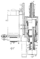
- Fig. 1 is a side, partly cross-sectional, view of a device in accordance with the invention.
- Fig. 2 is a side, partly cross-sectional, view of the actuating means, and the raising and lowering devices for the collection bottom.
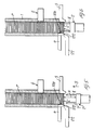
- Fig. 3 is an enlarged partial side view of the device in accordance with the previous figures, related to the magazine area for the sheet stack.
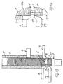
- Fig. 4 is a partial top view of the means for removing the proportioned pack from the collection bottom.
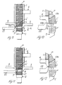
- Figures 5 to 16 schematic side views, show the various operating phases for the formation of the sheet pack based on the method of the invention.
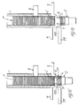
- Figures 1 to 4 show a device for forming proportioned packs of trimmed metal sheets, for the manufacture of armatures of electrical machinery or the like.
- Said device includes a vertical magazine 1 for a sheet stack P ( Figures 5 to 16). Magazine 1 is tubular and is correspondingly open at its lower end. There is associated therewith a coaxial collection bottom 2 which is supported in a raisable and lowerable manner with respect to magazine 1 itself.
- the lower end of magazine 1 is provided with a clamp for a part of the lower sheets of stack P which is comprised of a fixed jaw 3, on a side of magazine 1, and which active clamping surface extends essentially aligned with the internal surface of magazine 1.
- the very opposite side of magazine 1 is provided with a mobile jaw 4 which can be radially moved in both directions with respect to the axis of magazine 1.
- the mobile jaw 4 is actuated by an actuator 5 which can be of any type, for instance, hydraulic, pneumatic or mechanical, and which is connected to the jaw by a suitable transmission 105 (not shown in detail).
- the radial position of both jaws 3 and 4 can be adjusted with respect to magazine 1, as the jaws are respectively mounted on a radial sliding guide or on a radially moving slide.
- Jaws 3, 4 of the clamp act together with one or more lower sheets of stack P, clamping between them the peripheral edges of the sheets on diametrically opposed sides, so as to prevent gravity descent of stack P in magazine 1.
- mobile jaw 4 has an active surface 104 which extends towards the bottom and is vertically tilted, in the direction of magazine 1 itself, towards the bottom, ending with its lower end flush with lower sheet L' of stack P.
- a vice 6 which is provided with a radially sliding presser 106 and which clamps a part of stack P sheets against the opposite internal side of magazine 1.
- Vice 6 can be actuated like mobile jaw 4 of the clamp by an actuator 206 and allows a reduction of the weight of the overlying stack of sheets on the lower sheets of stack P acting together with the clamp.
- the collection bottom 2 has two sheet guiding and centring vertical pins 7 and 8.
- Pins 7 and 8 protrude from the upper side of the collection bottom 2 and, in the position for raising said bottom 2 for collection of sheet pack P, said pins 7, 8 penetrate, to a certain extent, inside stack P, engaging the internal profile of the sheets.
- the sheet guiding and centring means can also be accomplished otherwise in accordance with the specific profile of the sheets.
- the collection bottom 2 is comprised of the upper head of a cup element which is supported in a rotating manner with respect to it on the upper end of a threaded shaft 9.
- the threaded shaft 9 is supported in an axially sliding way by a slide 10 which is comprised of two guiding rods 110 parallel between them and with respect to shaft 9.
- the guiding rods 110 are engaged in non-illustrated tubular guides and are placed on diametrically opposed sides of shaft 9. They are connected between them on their traverse ends 210, 310 which are provided with a central hole which engages threaded shaft 9 and at least one of them 310 holds shaft 9 in a non-rotating way by means of radial keys 12.
- threaded shaft 9 Sliding of threaded shaft 9 occurs through a threaded sleeve 13, or similar, which is supported in a non-axially sliding way but rotating in a cylindrical body 14.
- the threaded sleeve 13 is rotating integrally with an actuating pulley 15 which is dynamically connected through a driving belt 16 to a pulley 17 keyed on the shaft of a motor 18.
- the motor 18 is preferably comprised of a step motor to which is attached a control gearcase (not shown) by which one can control very precisely the extent of the raising and lowering of the collection bottom 2 from counting the steps of motor 18 and thus the distance of bottom 2 from the last lower sheet L' which is held in magazine 1 for separation of pack P'.
- the threaded shaft 9 is tubular and it houses inside itself, in a rotating way with respect to itself and axially sliding together, a shaft 19 which serves to rotate the collection bottom 2.
- the rotating shaft 19 protrudes beyond the lower end of threaded shaft 9 and beyond traverse 310 which connects guiding rods 110 of support slide 10, dynamically connecting through its lower end to an actuating and rotating motor 20 which is supported by the same traverse 310.
- the upper end of rotating shaft 19 protrudes too beyond the end of threaded shaft 9 and beyond corresponding traverse 210 and is engaged by rotation to the cup element comprising the bottom collection 2 by means of a radial key 21.
- the collection bottom 2 can thus be raised or lowered to a predefined extent with respect to magazine 1 which is rotated on itself coaxially with magazine 1 and sheet stack P.
- detachment finger 22 Directly beneath mobile jaw 4 of the clamp there is a detachment finger 22 which can be raised and lowered with respect to the horizontal plane containing the lower edge of active surface 104 of jaw 4 of the clamp and the lower side of lower sheet L' of stack P and which can be further moved in both directions in the radial direction of magazine 1.
- the detachment finger 22 is supported on a first radially sliding slide 23 which is engaged on a radial guide 24 and actuated by an actuator 25, pneumatic or other type.
- Radial guide 24 is supported by a vertically sliding slide generally indicated by 26 and actuated by a separate actuator 27 similar to the one used for slide 23.
- the detachment finger 22 has a detachment tooth 122 which protrudes both upwards and towards magazine 1.
- said corner 122 is brought in readiness position right under the protruding lower edge of active surface 104 of jaw 4 and slightly moved backward with respect to said lower edge.
- the detachment finger 22 is radially moved in position of vertical alignment with the lower edge of active surface 104 of jaw 4 and subsequently in the axial direction of magazine 1, downwards.
- the device provides a unit for collecting the sheet pack from collection bottom 2.
- This unit includes a transfer clip 30 which is placed at the level of collection bottom 2 in its position of second lowering, in which guiding and centring pins 7 and 8 are solidly disengaged from the sheet stack P held in magazine 1.
- the transfer clip 30 is supported in a radially sliding way with respect to collection bottom 2 by a slide generally indicated by 31 which is mounted on radial guides 32.
- the transfer clip 30 grasps the sheet pack formed on collection bottom 2 and brings it to a transfer station where it is taken away by transport means 33.
- Said means are comprised, for example, of a rotating plate 34 which is placed under transfer clip 30 and can be raised or lowered with respect to it by actuating means 35.
- Said plate 34 has, distributed along its peripheral area, several magazines 36 which are similar to collection bottom 2 and are also provided with sheet guiding and centring vertical pins 7 and 8.
- the sheet pack held by transfer clip 30 is brought in a position which coincides with said magazines 36 which are raised against the pack.
- the transfer station is provided with a probe 37 for measuring the height of pack P' which includes a vertical palpating rod 137 which slides axially with respect to the sheet pack held in transfer clip 30 and to which are connected sensors/translators of the position of said palpating rod 137.
- FIGS 5 to 16 schematically show the phases for forming the sheet pack P' by means of the method and device in accordance with the invention.
- sheet stack P is blocked in magazine 1 against a downwards gravity slide by clamp 3, 4 and by overlying vice 6.
- Collection bottom 2 is moved (arrow S) from its resting position to a raising position (Fig. 6) where it is placed at a predefined distance H from lower sheet L' of stack P. Said distance is predefinable and adjustable through the actuator described above.
- the detachment finger 22 is in inactive readiness position, radially backed with respect to the lower edge of active surface 104 of mobile jaw 4. In this position, pins 7, 8 for guiding and centring collection bottom 2 are engaged with the associated profile parts of a predetermined number of lower sheets of stack P. Subsequently (Fig.
- the last sheet L belonging to detached pack P' can remain engaged, for a limited portion of its thickness, in clamp 3, 4, thus protruding at the bottom beyond the lower edge of active surface 104 of mobile jaw 4.
- the sheet pack P' formed on the collection bottom is missing one sheet, while sheet L precariously held by clamp 3, 4 can fall suddenly during subsequent process phases, causing damage, jamming and interruption of the operating cycle.
- sheet L can remain only moderately stuck to the lower sheet L' of stack P which constitutes the lower sheet of the successive pack due to the presence of lubricant oil, oxides, annealing, and the like.
- the detachment finger 22 is activated.
- the detachment finger 22 is moved from its readiness position, radially (arrow R) towards the axis of sheet stack P in a position of alignment with the lower end of active clamping surface 104 of mobile jaw 4 and thus strikes the part protruding beyond itself of sheet L erroneously and precariously held on the lower side of stack P ( Figures 11 and 12).
- said detachment finger 22 proceeds to a second vertical lowering (arrow A), as shown in Figures 13 and 14, causing the detachment and fall on sheet pack P' of the last sheet L' erroneously held by clamp 3, 4.
- the detachment finger 22 is again radially moved from sheet stack P, and brought back to its readiness position, as shown by Fig. 5.
- Collection bottom 2 accomplishes a second lowering, disengaging guiding and centring pins 7 and 8 from the sheet stack P which is blocked in magazine 1, while pack P' alone can be grasped by transfer clip 30.
- Compression means are brought back to inactive position after reclosure of clamp 3, 4 and vice 6.
- the invention also provides for the armature to be formed by several packs of superimposed sheets which are rotated among themselves to a predefined extent essentially based on their configuration.
- the bottom 2 is rotated for a predetermined angular measure, 180° for example.
- Each armature can be formed by several packs of superimposed sheets which are angularly staggered among themselves, the number of which can be predetermined based on the dimensional precision required and imposed by the material's tolerances.
Landscapes
- Engineering & Computer Science (AREA)
- Power Engineering (AREA)
- Manufacturing & Machinery (AREA)
- Mechanical Engineering (AREA)
- Pile Receivers (AREA)
- Stacking Of Articles And Auxiliary Devices (AREA)
- Sheets, Magazines, And Separation Thereof (AREA)
Claims (12)
- Verfahren zum automatischen Bilden von zugerichteten Blechpaketen für die Herstellung von Ankem elektrischer Maschinen oder dergleichen durch automatisches Präzisionszumessen des Blechplattenpaketes (P'), bestehend aus dem Sammeln und Trennen einer vorbestimmten Anzahl von Platten entsprechend einer vorbestimmten Höhe des Paketes (P') aus einem Plattenstapel (P), wobei das Verfahren mittels einer Vorrichtung durchgeführt wird, die mit einem vertikalen Magazin (1) für einen Plattenstapel (P) versehen ist, der am Boden offen ist und dessen unteres Ende einem anhebbaren und absenkbaren Sammelboden (2) für das Plattenpaket (P') zugeordnet ist, dadurch gekennzeichnet, daß das Verfahren die folgenden Phasen zum Bilden des Plattenpaketes (P') aufweist:- Verschieben des Sammelbodens (2) in einer erhöhte Position in einem vorbestimmten Abstand von der unteren Platte (L') des vertikalen Plattenstapels (P), der gegen ein Fallen durch Schwerkraft zu dem Sammelboden (2) hin von mindestens einer Klemmeinrichtung (3, 4) gehalten wird, die mit den Umfangskanten der einen oder mehreren unteren Platten des Stapels (P) zusammenwirkt, wobei dieser Abstand einer vorbestimmten Höhe des zu sammelnden Plattenstapels (P') oder einer bestimmten Zahl von Platten des Stapels (P) entspricht;- Öffnen der Klemmeinrichtung (3, 4) und Gleiten des Plattenstapels (P) durch Schwerkraft zu dem Sammelboden (2) hin in einem Maße, welches der vorbestimmten Höhe des Plattenpaketes (P') entspricht;- Abtrennen des Plattenpaketes (P') von dem darüberliegenden Plattenstapel (P) durch Wiederverschließen der Klemmeinrichtung (3, 4) und ein erstes Absenken des Sammelbodens (2) durch Ablösen des Plattenpaketes (P') von dem darüberliegenden Stapel (P);- Ablösen jeder letzten Platte (L) des abgetrennten Paketes (P'), die irrtümlich infolge ihrer Dicke durch die Klemmeinrichtung (3, 4) gehalten blieb und mäßig an der unteren Platte (L') des Plattenstapels (P) haften blieb mit der Absicht, die erste untere Platte eines nachfolgenden Paketes zu werden und die sich somit am Boden mindestens teilweise über die untere Kante der Klemmeinrichtung (3, 4) hinaus erstreckt, und zwar aufgrund eines Ablösefingers (22), der nach der Trennstufe und dem ersten Absenken des Sammelbodens (2) in Tätigkeit gebracht wird in dem Sinne, daß dieser Ablösefinger (22) aus seiner Bereitschaftsposition radial zur Achse des Plattenstapels (P) hin bewegt wird, wo er gegen eine vorstehende Kante einer Platte (L') schlägt, welche Platte irrtümlich an dem Plattenpaket (P) haften blieb, und danach der Ablösefinger (22) einem zweiten vertikalen Absenken unterworfen wird mit der Folge des Ablösens und Fallens der letzten von den Klemmeinrichtungen (3, 4) irrtümlich gehaltenen Platte auf das Plattenpaket (P').
- Verfahren nach Anspruch 1, dadurch gekennzeichnet, daß der Sammelboden (2) mit Plattenführungs- und -zentriermitteln (7, 8) versehen ist, die von der oberen Seite des Bodens (2) vertikal zu dem Plattenstapel (P) hervorragen und deren Länge derart ist, daß in der angehobenen Position des Sammelbodens (2) zum Stapel (P) hin mindestens eine untere Platte (L'), vorzugsweise eine Anzahl von unteren Platten des Plattenstapels (P) so in Eingriff tritt, daß nach dem ersten Ablösen unter Absenken des Sammelbodens (2) die Führungs- und -zentriermittel (7, 8) noch mit der letzten unteren Platte (L') des Stapels (P) in Eingriff sind, während das Ablösen von einem zweiten Absenken des Sammelbodens (2) für das Loslassen der Führungs- und -zentriermittel (7, 8) von dem darüberliegenden Plattenstapel (P) gefolgt wird.
- Verfahren nach Anspruch 1 oder 2, dadurch gekennzeichnet, daß das Ablösen unabhängig davon erfolgt, ob am Boden des Stapels (P) eine unsicher gehaltene Platte (L) vorhanden ist oder nicht
- Verfahren nach einem der vorhergehenden Ansprüche, dadurch gekennzeichnet, daß unmittelbar vor dem Wiederschließen der Klemmeinrichtung (3, 4) zum Trennen des Plattenpaketes (P') von dem darüberliegenden Stapel (P) in dem Magazin (1) auf den Plattenstapel (P) und auf das darunterliegende Paket (P') eine axiale Kompression gegen den Sammelboden (2) erfolgt, die nach dem Wederverschluß der Klemmeinrichtung (3, 4) beendet ist.
- Verfahren nach einem der vorhergehenden Ansprüche, dadurch gekennzeichnet, daß auf einem vorhergehenden Plattenpaket (P') auf dem Sammelboden (2) direkt ein oder mehrere Plattenpakete (P') gebildet werden, die perfekt vertikal ausgerichtet und unter sich selbst unter einem gewissen Winkel gedreht, basierend auf der Konfiguration der Platten, durch eine axiale Drehung des Sammelbodens (2) vor einem neuen Zyklus für das Sammeln jedes weiteren Paketes (P') übereinander angeordnet werden, während die Plattenführung- und -zentriermittel (7, 8) eine ausreichend größere Länge haben.
- Vorrichtung zur Durchführung des Verfahrens nach einem der vorhergehenden Ansprüche, mit:- einem vertikalen Magazin (1) für einen Stapel (P) von übereinanderangeordneten Platten, wobei das untere offene Ende des Magazins (1) mit einer Klemmeinrichtung (3, 4) versehen ist, welche den Plattenstapel (P) in dem Magazin (1) gegen Fallen durch Schwerkraft blockiert;- einem Boden (2) zum Sammeln mindestens eines Plattenpaketes (P') vom Stapel (P), der bezüglich dem Magazin (1) in einer koaxialen Position angeordnet und gestützt ist und vertikal in beide Richtungen axial geschoben werden kann und alternativ an verschiedenen, vorbestimmten Abständen von der unteren Platte (L') des Plattenstapels (P) in dem Magazin (1) auf der Stange einer linearen Betätigungseinrichtung (9, 10, 13, 18) angehalten werden kann;- dadurch gekennzeichnet, daß- ein Ablösefinger (22, 122), der auf Gleitstücken (23, 26) abgestützt ist, in einer vertikalen Richtung bzw. in einer radialen Richtung bezüglich dem Magazin (1) in beide Richtungen gerade unter die untere Kante der aktiven Klemmoberfläche (104) der Kleimmeinrichtung (3, 4) oder gerade unter die Ebene, welche die untere Seite der unteren Platte (L') des Plattenstapels (P) in dem Magazin (1) enthält, gleitet, um radial mit dem Umfangskantenteil in Eingriff zu kommen, welches über die untere Kante der Klemmeinrichtung (3, 4) einer Platte (L) hervorragt, die zu einem Plattenpaket (P') gehört, das von dem Stapel (P) separiert ist, und welche Platte (L) irrtümlich und unsicher gehalten ist, für einen Teil der Dicke ihrer Umfangskante durch die Klemmeinrichtung (3, 4) gegen die untere Platte (L') des Stapels (P) oder ungewiß bzw. unsicher gegen die untere Platte (L') haftet, wobei dieser Ablösefinger (22) in der Lage ist, vertikal zum Sammelboden (2) abgesenkt zu werden für das Ablösen der Platte (L), die unsicher gegen den Plattenstapel (P) gehalten ist, und danach in seine Bereitschaftsposition unter der Klemmeinrichtung (3, 4) zurückgebracht zu werden, die radial von der Umfangskante des Plattenstapels (P) unterlegt ist.
- Vorrichtung nach Anspruch 6, dadurch gekennzeichnet, daß der Sammelboden (2) mit Führungs- und -zentriermitteln (7, 8) versehen ist, die vertikal vom Sammelboden (2) zum Plattenstapel (P) hin vorragen und deren Ausgestaltung dem inneren oder äußeren Profil der Platten entspricht, um in einer entfernbaren Weise axial mit mindestens einer und vorzugsweise einigen unteren Platten des Stapels (P) in Eingriff zu kommen.
- Vorrichtung nach Anspruch 7, dadurch gekennzeichnet, daß die Führungs- und -zentriermittel (7, 8) eine solche Länge haben, daß sie während des Sammelns des Plattenpaketes (P') von dem Magazin (1) und Trennen jeder Platte (L), die irrtümlich gegen die untere Platte (L') des Stapels (P) gehalten ist, noch mit mindestens der unteren Platte (L') und vorzugsweise einigen unteren Platten des Stapels (P) in Eingriff stehen.
- Vorrichtung nach einem der Ansprüche 6 bis 8, dadurch gekennzeichnet, daß die Klemmeinrichtung (3, 4) mindestens einen mobilen Backen (4) aufweist, der radial in beide Richtungen bezüglich der Achse des Magazins (1) bewegt werden kann und dessen aktive Klemmoberfläche (104) nach unten vorsteht und zu der Achse des Magazins (1) hin nach unten geschwenkt wird, während der Ablösefinger (22) eine Ablöseecke (122) hat, die nach oben vorsteht zum unteren Ende der aktiven Klemmoberfläche (104) des mobilen Backens (4) hin und zu der Achse des Magazins (1) hin.
- Vorrichtung nach einem der vorhergehenden Ansprüche, dadurch gekennzeichnet, daß über der Klemmeinrichtung (3, 4) das Magazin (1) eine zwischengeschaltete, radiale Spanneinrichtung (6, 106) hat für das Blockieren des entsprechenden Teiles des Stapels (P) gegen ein Fallen durch Schwerkraft im Magazin (1), wobei die Spanneinrichtung (6) gleichzeitig mit dem Öffnen und Schließen der Klemmeinrichtung (3, 4) öffnet und schließt
- Vorrichtung nach einem der vorhergehenden Ansprüche, dadurch gekennzeichnet, daß der Sammelboden (2) ferner in einer drehenden Weise um seine Achse um einen vorbestimmten Winkel gehalten ist.
- Vorrichtung nach einem der vorhergehenden Ansprüche, dadurch gekennzeichnet, daß dem Magazin (1) Mittel (28, 29) für die axiale Kompression des Plattenstapels (P) gegen den Sammelboden (2) zugeordnet sind.
Applications Claiming Priority (2)
| Application Number | Priority Date | Filing Date | Title |
|---|---|---|---|
| ITGE930046 | 1993-05-26 | ||
| ITGE930046A IT1262275B (it) | 1993-05-26 | 1993-05-26 | Metodo e dispositivo per la formazione automatica di pacchi di lamierini metallici, tranciati, per la fabbricazione di armature di macchine elettriche, o simili. |
Publications (3)
| Publication Number | Publication Date |
|---|---|
| EP0632567A2 EP0632567A2 (de) | 1995-01-04 |
| EP0632567A3 EP0632567A3 (en) | 1995-01-25 |
| EP0632567B1 true EP0632567B1 (de) | 1997-01-22 |
Family
ID=11354437
Family Applications (1)
| Application Number | Title | Priority Date | Filing Date |
|---|---|---|---|
| EP94107753A Expired - Lifetime EP0632567B1 (de) | 1993-05-26 | 1994-05-19 | Verfahren und Vorrichtung zum automatischen Bilden von ausgerichteten Blechpaketen zur Herstellung von Ankern elektrischer Maschinen oder dergleichen |
Country Status (5)
| Country | Link |
|---|---|
| US (2) | US5537731A (de) |
| EP (1) | EP0632567B1 (de) |
| CA (1) | CA2124227A1 (de) |
| DE (1) | DE69401541T2 (de) |
| IT (1) | IT1262275B (de) |
Families Citing this family (8)
| Publication number | Priority date | Publication date | Assignee | Title |
|---|---|---|---|---|
| US5791038A (en) * | 1995-10-26 | 1998-08-11 | Libert; Thomas M. | Method of separating stator laminations |
| WO1998042134A1 (fr) | 1997-03-17 | 1998-09-24 | Mitsubishi Denki Kabushiki Kaisha | Codeur et decodeur d'image, methode de codage et de decodage d'image, et systeme de codage/decodage d'image |
| US5929551A (en) * | 1998-07-24 | 1999-07-27 | General Motors Corporation | Rotor section containment with steel punched star |
| EP1248347B1 (de) * | 2000-08-29 | 2008-01-23 | Mitsubishi Denki Kabushiki Kaisha | STATORBLECHKöRPER UND VERFAHREN ZUR HERSTELLUNG DESSELBEN |
| EP1764808A1 (de) | 2005-09-15 | 2007-03-21 | Siemens Aktiengesellschaft | Verfahren und Vorrichtung zur Herstellung eines Blechpacketes |
| US20070262668A1 (en) * | 2006-05-11 | 2007-11-15 | General Electric Company | Magnetic Bearings, Armatures for Magnetic Bearings, and Methods for Assembling the Same |
| EP2048390A3 (de) * | 2007-10-12 | 2009-08-05 | General Electric Company | Blechpaket mit beschichteten Blechen, Magnetlager mit einem Blechpaket und Verfahren zum Zusammenbau des Blechpaketes |
| IT201800007490A1 (it) * | 2018-07-25 | 2020-01-25 | Dema Srl | Metodo e Dispositivo per la formazione automatica di pacchi di lamierini metallici, per la formazione di armature di machine elettriche, o simili ed impianto per la produzione di armature di macchine elettriche o simili provvisto di detto dispositivo |
Family Cites Families (4)
| Publication number | Priority date | Publication date | Assignee | Title |
|---|---|---|---|---|
| DE142111C (de) * | ||||
| DD142111B1 (de) * | 1978-07-06 | 1982-11-24 | Juergen Hirsch | Verfahren und vorrichtung zum automatischen paketieren einer vielzahl von einzelnen blechen |
| AT379258B (de) * | 1982-11-15 | 1985-12-10 | Sticht Fertigungstech Stiwa | Einrichtung zum herstellen von paketen aus plattenfoermigen bauteilen |
| DE3735870A1 (de) * | 1987-10-07 | 1989-04-27 | Statomat Globe Maschf | Verfahren und vorrichtung zur abnahme von blechen von einem stapel |
-
1993
- 1993-05-26 IT ITGE930046A patent/IT1262275B/it active IP Right Grant
-
1994
- 1994-05-19 EP EP94107753A patent/EP0632567B1/de not_active Expired - Lifetime
- 1994-05-19 DE DE69401541T patent/DE69401541T2/de not_active Expired - Lifetime
- 1994-05-24 US US08/248,451 patent/US5537731A/en not_active Expired - Lifetime
- 1994-05-25 CA CA002124227A patent/CA2124227A1/en not_active Abandoned
-
1996
- 1996-02-28 US US08/608,333 patent/US5694679A/en not_active Expired - Lifetime
Also Published As
| Publication number | Publication date |
|---|---|
| DE69401541D1 (de) | 1997-03-06 |
| CA2124227A1 (en) | 1994-11-27 |
| ITGE930046A1 (it) | 1994-11-26 |
| US5694679A (en) | 1997-12-09 |
| US5537731A (en) | 1996-07-23 |
| DE69401541T2 (de) | 1997-06-26 |
| EP0632567A3 (en) | 1995-01-25 |
| ITGE930046A0 (it) | 1993-05-26 |
| EP0632567A2 (de) | 1995-01-04 |
| IT1262275B (it) | 1996-06-19 |
Similar Documents
| Publication | Publication Date | Title |
|---|---|---|
| EP0632567B1 (de) | Verfahren und Vorrichtung zum automatischen Bilden von ausgerichteten Blechpaketen zur Herstellung von Ankern elektrischer Maschinen oder dergleichen | |
| CN113794336B (zh) | 一种自动拆除电机定子绕组的设备及其方法 | |
| JP2021532725A (ja) | 金属積層物の集合体を自動的に形成するための方法及び装置 | |
| CN107243682A (zh) | 低压断路器电磁组件焊装系统与焊接方法 | |
| CN108311631B (zh) | 电刷架底板与绝缘板自动铆接设备 | |
| CN109896280A (zh) | 一种继电器自动装盘机 | |
| CN114704555A (zh) | 冲压外圈轴承装针及灵活性检测机 | |
| CN114798950A (zh) | 一种具有自动给料装置的数控冲床 | |
| CN111822978B (zh) | 毛细管装配机 | |
| US2881929A (en) | Blank feeder and stacker | |
| CN109772985B (zh) | 一种摩托车齿轮冲压装置 | |
| CN111874628A (zh) | 一种薄片材料高速连续上料系统 | |
| US4658492A (en) | Coil assembly machine | |
| CN217207388U (zh) | 冲压外圈轴承装针及灵活性检测机 | |
| CN115055960B (zh) | 一种半成品定时器自动组装设备 | |
| JP3490524B2 (ja) | コイルの製造装置及び製造方法 | |
| CN212305068U (zh) | 一种定转子冲槽自动化生产装置 | |
| EP0592929B1 (de) | Maschine zur Herstellung von Stator-Blechpaketen | |
| JP4079758B2 (ja) | 電動機ステータからの巻線コイル分離方法とその装置 | |
| JPH07136728A (ja) | プレス機への材料供給処理装置 | |
| CN112935773A (zh) | 一种螺栓自动拆解分离机 | |
| CN216356375U (zh) | 一种自动拆除电机定子绕组的设备 | |
| CN205294235U (zh) | 一种机器人抓取整体物料的系统 | |
| CN115446593A (zh) | 一种磁环压装机构 | |
| CN209439330U (zh) | 旋转式机械手连续冲压自动化生产线的片料分离机 |
Legal Events
| Date | Code | Title | Description |
|---|---|---|---|
| PUAI | Public reference made under article 153(3) epc to a published international application that has entered the european phase |
Free format text: ORIGINAL CODE: 0009012 |
|
| PUAL | Search report despatched |
Free format text: ORIGINAL CODE: 0009013 |
|
| AK | Designated contracting states |
Kind code of ref document: A2 Designated state(s): CH DE ES FR GB LI SE |
|
| AK | Designated contracting states |
Kind code of ref document: A3 Designated state(s): CH DE ES FR GB LI SE |
|
| 17P | Request for examination filed |
Effective date: 19950320 |
|
| 17Q | First examination report despatched |
Effective date: 19951206 |
|
| GRAG | Despatch of communication of intention to grant |
Free format text: ORIGINAL CODE: EPIDOS AGRA |
|
| GRAH | Despatch of communication of intention to grant a patent |
Free format text: ORIGINAL CODE: EPIDOS IGRA |
|
| GRAH | Despatch of communication of intention to grant a patent |
Free format text: ORIGINAL CODE: EPIDOS IGRA |
|
| GRAA | (expected) grant |
Free format text: ORIGINAL CODE: 0009210 |
|
| AK | Designated contracting states |
Kind code of ref document: B1 Designated state(s): CH DE ES FR GB LI SE |
|
| PG25 | Lapsed in a contracting state [announced via postgrant information from national office to epo] |
Ref country code: ES Free format text: THE PATENT HAS BEEN ANNULLED BY A DECISION OF A NATIONAL AUTHORITY Effective date: 19970122 |
|
| REG | Reference to a national code |
Ref country code: CH Ref legal event code: EP |
|
| ET | Fr: translation filed | ||
| REG | Reference to a national code |
Ref country code: CH Ref legal event code: NV Representative=s name: PATENTANWALTSBUERO FELDMANN AG |
|
| REF | Corresponds to: |
Ref document number: 69401541 Country of ref document: DE Date of ref document: 19970306 |
|
| PG25 | Lapsed in a contracting state [announced via postgrant information from national office to epo] |
Ref country code: SE Effective date: 19970422 |
|
| PLBE | No opposition filed within time limit |
Free format text: ORIGINAL CODE: 0009261 |
|
| STAA | Information on the status of an ep patent application or granted ep patent |
Free format text: STATUS: NO OPPOSITION FILED WITHIN TIME LIMIT |
|
| 26N | No opposition filed | ||
| REG | Reference to a national code |
Ref country code: GB Ref legal event code: IF02 |
|
| REG | Reference to a national code |
Ref country code: CH Ref legal event code: PFA Owner name: SASSI S.R.L. Free format text: SASSI S.R.L.#VIA E. VECCHIA 100#I-17019 VARAZZE (SAVONA) (IT) -TRANSFER TO- SASSI S.R.L.#VIA E. VECCHIA 100#I-17019 VARAZZE (SAVONA) (IT) |
|
| PGFP | Annual fee paid to national office [announced via postgrant information from national office to epo] |
Ref country code: FR Payment date: 20100419 Year of fee payment: 17 |
|
| PGFP | Annual fee paid to national office [announced via postgrant information from national office to epo] |
Ref country code: CH Payment date: 20100826 Year of fee payment: 17 |
|
| PGFP | Annual fee paid to national office [announced via postgrant information from national office to epo] |
Ref country code: GB Payment date: 20100415 Year of fee payment: 17 Ref country code: DE Payment date: 20100707 Year of fee payment: 17 |
|
| REG | Reference to a national code |
Ref country code: DE Ref legal event code: R119 Ref document number: 69401541 Country of ref document: DE |
|
| REG | Reference to a national code |
Ref country code: DE Ref legal event code: R119 Ref document number: 69401541 Country of ref document: DE |
|
| REG | Reference to a national code |
Ref country code: CH Ref legal event code: PL |
|
| GBPC | Gb: european patent ceased through non-payment of renewal fee |
Effective date: 20110519 |
|
| PG25 | Lapsed in a contracting state [announced via postgrant information from national office to epo] |
Ref country code: CH Free format text: LAPSE BECAUSE OF NON-PAYMENT OF DUE FEES Effective date: 20110531 Ref country code: LI Free format text: LAPSE BECAUSE OF NON-PAYMENT OF DUE FEES Effective date: 20110531 |
|
| REG | Reference to a national code |
Ref country code: FR Ref legal event code: ST Effective date: 20120131 |
|
| PG25 | Lapsed in a contracting state [announced via postgrant information from national office to epo] |
Ref country code: FR Free format text: LAPSE BECAUSE OF NON-PAYMENT OF DUE FEES Effective date: 20110531 |
|
| PG25 | Lapsed in a contracting state [announced via postgrant information from national office to epo] |
Ref country code: GB Free format text: LAPSE BECAUSE OF NON-PAYMENT OF DUE FEES Effective date: 20110519 |
|
| PG25 | Lapsed in a contracting state [announced via postgrant information from national office to epo] |
Ref country code: DE Free format text: LAPSE BECAUSE OF NON-PAYMENT OF DUE FEES Effective date: 20111130 |