EP0631991B1 - Procédé et appareil pour le conditionnement et l'homogénéisation d'un courant de verre - Google Patents
Procédé et appareil pour le conditionnement et l'homogénéisation d'un courant de verre Download PDFInfo
- Publication number
- EP0631991B1 EP0631991B1 EP94108596A EP94108596A EP0631991B1 EP 0631991 B1 EP0631991 B1 EP 0631991B1 EP 94108596 A EP94108596 A EP 94108596A EP 94108596 A EP94108596 A EP 94108596A EP 0631991 B1 EP0631991 B1 EP 0631991B1
- Authority
- EP
- European Patent Office
- Prior art keywords
- glass
- section
- depth
- temperature
- flow
- Prior art date
- Legal status (The legal status is an assumption and is not a legal conclusion. Google has not performed a legal analysis and makes no representation as to the accuracy of the status listed.)
- Expired - Lifetime
Links
- 239000011521 glass Substances 0.000 title claims abstract description 127
- 230000003750 conditioning effect Effects 0.000 title claims abstract description 9
- 238000000034 method Methods 0.000 title claims description 20
- 238000001816 cooling Methods 0.000 claims abstract description 106
- 238000009826 distribution Methods 0.000 claims description 45
- 238000000265 homogenisation Methods 0.000 claims description 30
- 230000008569 process Effects 0.000 claims description 15
- 238000007654 immersion Methods 0.000 claims description 8
- 238000004519 manufacturing process Methods 0.000 claims description 8
- 238000003756 stirring Methods 0.000 claims description 6
- 239000005401 pressed glass Substances 0.000 claims description 2
- 230000000694 effects Effects 0.000 abstract description 14
- 230000001143 conditioned effect Effects 0.000 abstract description 2
- 230000000630 rising effect Effects 0.000 abstract description 2
- 238000002844 melting Methods 0.000 description 29
- 230000008018 melting Effects 0.000 description 29
- 230000005855 radiation Effects 0.000 description 20
- 239000000155 melt Substances 0.000 description 13
- 239000000156 glass melt Substances 0.000 description 11
- 238000010438 heat treatment Methods 0.000 description 8
- 238000012545 processing Methods 0.000 description 8
- 230000015572 biosynthetic process Effects 0.000 description 6
- 239000010410 layer Substances 0.000 description 6
- 238000010276 construction Methods 0.000 description 4
- 210000001061 forehead Anatomy 0.000 description 4
- 239000000203 mixture Substances 0.000 description 4
- 230000001419 dependent effect Effects 0.000 description 3
- 238000010586 diagram Methods 0.000 description 3
- 238000000605 extraction Methods 0.000 description 3
- 238000009413 insulation Methods 0.000 description 3
- XEEYBQQBJWHFJM-UHFFFAOYSA-N Iron Chemical compound [Fe] XEEYBQQBJWHFJM-UHFFFAOYSA-N 0.000 description 2
- 239000013078 crystal Substances 0.000 description 2
- 238000013461 design Methods 0.000 description 2
- 238000004031 devitrification Methods 0.000 description 2
- 238000003780 insertion Methods 0.000 description 2
- 230000037431 insertion Effects 0.000 description 2
- 230000021715 photosynthesis, light harvesting Effects 0.000 description 2
- 230000009467 reduction Effects 0.000 description 2
- 238000007670 refining Methods 0.000 description 2
- 238000012876 topography Methods 0.000 description 2
- 229910000838 Al alloy Inorganic materials 0.000 description 1
- VYZAMTAEIAYCRO-UHFFFAOYSA-N Chromium Chemical compound [Cr] VYZAMTAEIAYCRO-UHFFFAOYSA-N 0.000 description 1
- 206010037660 Pyrexia Diseases 0.000 description 1
- 241000863032 Trieres Species 0.000 description 1
- 230000003321 amplification Effects 0.000 description 1
- 230000004888 barrier function Effects 0.000 description 1
- 238000007664 blowing Methods 0.000 description 1
- 230000015556 catabolic process Effects 0.000 description 1
- 239000000919 ceramic Substances 0.000 description 1
- 229910052804 chromium Inorganic materials 0.000 description 1
- 239000011651 chromium Substances 0.000 description 1
- 230000002301 combined effect Effects 0.000 description 1
- 239000004035 construction material Substances 0.000 description 1
- 239000002826 coolant Substances 0.000 description 1
- 230000003247 decreasing effect Effects 0.000 description 1
- 238000006731 degradation reaction Methods 0.000 description 1
- 230000003111 delayed effect Effects 0.000 description 1
- 238000011161 development Methods 0.000 description 1
- 230000018109 developmental process Effects 0.000 description 1
- 239000005357 flat glass Substances 0.000 description 1
- 239000002737 fuel gas Substances 0.000 description 1
- 239000007789 gas Substances 0.000 description 1
- 239000003365 glass fiber Substances 0.000 description 1
- 230000012447 hatching Effects 0.000 description 1
- 210000003128 head Anatomy 0.000 description 1
- 229910052500 inorganic mineral Inorganic materials 0.000 description 1
- 239000012774 insulation material Substances 0.000 description 1
- 230000003993 interaction Effects 0.000 description 1
- 229910052742 iron Inorganic materials 0.000 description 1
- -1 iron-chromium-aluminum Chemical compound 0.000 description 1
- 239000007788 liquid Substances 0.000 description 1
- 239000011707 mineral Substances 0.000 description 1
- 238000002156 mixing Methods 0.000 description 1
- 238000003199 nucleic acid amplification method Methods 0.000 description 1
- 230000000737 periodic effect Effects 0.000 description 1
- 230000035699 permeability Effects 0.000 description 1
- 230000001105 regulatory effect Effects 0.000 description 1
- 238000010079 rubber tapping Methods 0.000 description 1
- 230000007480 spreading Effects 0.000 description 1
- 238000003892 spreading Methods 0.000 description 1
- 239000002344 surface layer Substances 0.000 description 1
- 239000010409 thin film Substances 0.000 description 1
- 238000012546 transfer Methods 0.000 description 1
- 238000011144 upstream manufacturing Methods 0.000 description 1
Images


Classifications
-
- C—CHEMISTRY; METALLURGY
- C03—GLASS; MINERAL OR SLAG WOOL
- C03B—MANUFACTURE, SHAPING, OR SUPPLEMENTARY PROCESSES
- C03B5/00—Melting in furnaces; Furnaces so far as specially adapted for glass manufacture
- C03B5/16—Special features of the melting process; Auxiliary means specially adapted for glass-melting furnaces
- C03B5/23—Cooling the molten glass
-
- C—CHEMISTRY; METALLURGY
- C03—GLASS; MINERAL OR SLAG WOOL
- C03B—MANUFACTURE, SHAPING, OR SUPPLEMENTARY PROCESSES
- C03B7/00—Distributors for the molten glass; Means for taking-off charges of molten glass; Producing the gob, e.g. controlling the gob shape, weight or delivery tact
- C03B7/02—Forehearths, i.e. feeder channels
- C03B7/06—Means for thermal conditioning or controlling the temperature of the glass
-
- Y—GENERAL TAGGING OF NEW TECHNOLOGICAL DEVELOPMENTS; GENERAL TAGGING OF CROSS-SECTIONAL TECHNOLOGIES SPANNING OVER SEVERAL SECTIONS OF THE IPC; TECHNICAL SUBJECTS COVERED BY FORMER USPC CROSS-REFERENCE ART COLLECTIONS [XRACs] AND DIGESTS
- Y02—TECHNOLOGIES OR APPLICATIONS FOR MITIGATION OR ADAPTATION AGAINST CLIMATE CHANGE
- Y02P—CLIMATE CHANGE MITIGATION TECHNOLOGIES IN THE PRODUCTION OR PROCESSING OF GOODS
- Y02P40/00—Technologies relating to the processing of minerals
- Y02P40/50—Glass production, e.g. reusing waste heat during processing or shaping
- Y02P40/57—Improving the yield, e-g- reduction of reject rates
Definitions
- the invention relates to a method for conditioning and homogenizing a continuously flowing glass stream in a treatment line, which extends from an inlet side of a work tub or a distribution channel to at least one removal point and in which there is at least one cooling zone, to which at least one homogenization zone for the Glass temperature adjoins, the temperature in the work tub or the distribution channel being lowered from an inlet temperature T 1 to an outlet temperature T 2 , preferably for producing molded glass parts such as hollow glass parts and pressed glass parts.
- the process temperatures when melting glass depend on its composition, the production process and other factors, the temperatures required for processing the glass are generally lower than the melting temperatures during the manufacture of the glass. As a result, the glass must be cooled between its manufacture and processing.
- the cooling of the glass is part of the so-called “conditioning", in which the glass is prepared for processing.
- the conditioning of the glass also includes achieving a degree of thermal homogeneity required for the processing process in question.
- the glass can only be conditioned when the glass has already left the actual melting unit.
- conditioning was at least predominantly carried out in the so-called forehearths or feeders.
- work tub or the distribution channel has been used for conditioning.
- the specific melting performance i.e. the performance related to the area of the melting range, significantly increased.
- the temperature of the glass removed from the melting tank has risen accordingly.
- Other aids that increase the glass temperature at the bottom of the melting tank, such as. B. bubbler or floor heating mostly lead to an increase in the outlet temperature of the glass from the melting tank.
- the glass processing machines have also been continuously developed to increase throughput, among other things. While still in the sixties and seventies machines for the mass production of hollow glasses 6, 8 or 10 stations were provided for two drops each, larger machines today have 12 to 16 stations for two drops each or ten stations for three or four drops each. As a result, the throughput of a single machine has increased considerably.
- the influences described above have resulted in the total amount of heat which has to be removed from the glass after leaving the melting tank and before processing being increased considerably.
- the increase in the throughput of the individual machines has reduced the dwell time of the glass in the parts of the plant downstream of the melting tank. This leads to the contrary fact that a larger amount of heat has to be dissipated within a shorter time. This means that the productivity of the entire line depends very much on the cooling capacity within the treatment line.
- numerous technical problems must be taken into account again.
- the flow of the glass in work tanks and forehearths which generally have the basic shape of a channel, takes place in the form of a laminar flow due to the relatively high viscosity of the glass.
- a speed profile is formed in the glass bath in which the maximum lies approximately in the middle of the flow channel or on the glass surface. Due to the dependence of the viscosity on the temperature of the glass melt, there is an interaction between the glass temperature, the heat losses and the flow rate of the glass. If the speed is reduced locally, the heat losses are increased by increasing the dwell time. This causes the temperature to drop further and the resulting increase in viscosity further reduces the local flow rate.
- the heat transport in the glass bath itself takes place almost exclusively by radiation, whereby the transport speed depends on the composition of the glass.
- the presence of divalent iron or chromium, which are used to color green glass reduces the heat transport in the glass bath compared to, for example, a lime-soda white glass. Analogous conditions also apply to amber glass. As a result, the heat transfer from the lower areas of the glass bath is delayed. However, cooling the lower areas of the glass bath is essential. If the cooling occurs too late When this happens, no effective cooling effect is observed in the lower areas of the glass bath.
- the prior art mainly deals with the cooling of the glass flow in feeders or forehearths, which are generally connected downstream of a distribution channel.
- the bottom of a working trough or a distribution channel (to the forehearths) runs in a ramp shape, so that extremely unfavorable cooling conditions for the melt are present, particularly in the deep part of the working troughs and distribution channels.
- the reason for this can be seen in the fact that at least predominantly energy extraction from a glass melt can or must only take place by radiation, and here the radiation becomes more and more unfavorable with increasing bath depth because the glass above it absorbs the energy again.
- the conditions are particularly unfavorable for amber glass and green glass, which absorb the longer-wave heat radiation to a considerable extent.
- Trier uses a diagram to indicate that the radiation conductivity of brown glass and green glass at a temperature of 1300 ° C is only about 1/4 to 1 / 6 the radiation conductivity of white glass (commercial glass, window glass). This results in significantly deteriorated cooling conditions with increasing bath depth and increasing glass color. In an analogous manner, however, this leads to the formation of an increasingly increasing temperature gradient between the bath surface and the floor area of the bath, so that a forced flow through a slowly flowing, cooler surface layer forms a rapidly flowing, hotter floor layer.
- the invention is therefore based on the object of specifying a method of the type described at the outset, by means of which both a strong cooling effect and a good homogenization effect are produced with a high throughput of the treatment section. As was shown at the beginning, these demands are diametrically opposed to one another.
- the object is achieved in the above-mentioned method according to the invention in that in the at least one cooling zone of the work tub or the distribution channel by means of at least one elevation projecting from the floor, a flow cross section of the glass mass with a depth / width ratio T / B of at most 0.6 is set, the maximum depth T max being 300 mm, and that in the glass flow in the sum of all the cooling zones of the working tub or the distribution channel, at least 50% of the temperature difference between T 1 and T 2 is reduced.
- the invention consists in producing as low a level as possible of the glass melt in the work tub or in the distribution channel in the area of the cooling zone (s) by at least one threshold-like elevation in the area, drawing as much heat as possible in this area of the low level, so that at Given the given length of the entire treatment section, the longest possible homogenization zone is available, in which an equalization of the remaining temperature differences can be brought about.
- the advantages first increase with decreasing depth, then z. B. if the maximum depth T max when arranging the cooling zone in a work tub or in a distribution channel can also be selected to be less than 300 mm, for example 250 mm, 200 mm or less.
- the specified low bath depths are by no means a matter of course for the high throughputs required today. This is opposed by the effect that a gradient dependent on the flow velocity occurs over the length of the cooling zone and the rest of the flow path, and the flow velocity and thus the gradient increase sharply with a smaller bath depth.
- the idea according to the invention is therefore aimed in the direction of "locally limited thin-film cooling", so that it is possible to use the cooling systems known per se to remove extremely large amounts of heat in a relatively short way, ie locally limited to the region of the elevations, in relation to the temperature difference to be placed between T 1 and T 2 .
- the temperature T 1 is that at the outlet of the melting tank or at the entry into the work tank or the distribution channel and the temperature T 2 is the outlet temperature from the work tank or the distribution channel.
- the temperature T 1 is a consequence of the necessary operating conditions in the melting tank and is usually, but by way of example, between 1350 and 1400 ° C.
- the temperature T 1 is generally higher, the higher the throughput or the performance of the melting tank.
- the temperature T 2 is predetermined both by the type of glass and by the processing conditions of the glass droplets usually produced and is generally between 1120 and 1180 ° C. by way of example.
- measures or means known per se can be used for heat removal, such as, for example, floor cooling through cooling channels built into the floor of the treatment section and / or through insulation which is deliberately reduced in the floor area.
- a Surface cooling can be provided, such as by adjustable ceiling openings, and / or by blowing with gases, for example with air and / or by heat sinks, which are arranged above the glass mirror without contact with the glass flow.
- gases for example with air and / or by heat sinks
- Known means can also be provided for the subsequent homogenization of the temperature in the glass melt, such as a correspondingly long homogenization zone with the prerequisite for the most complete possible thermal insulation from the environment, by uncooled stirring elements or guide surfaces, and likewise by slightly heating the melt from above by radiation or within the glass by the electrical glass resistance and corresponding heating electrodes.
- the thin-layer cooling according to the invention in the shortest possible way can achieve that the flow path of the glass mass in the cooling zone is essentially straight, so that so-called “dead” Corners "and additional heating of the glass in these dead corners can be avoided.
- the structure of the or each cooling zone is simplified considerably and the temperature distribution is already largely homogenized in the cooling zone.
- the invention also relates to a device for carrying out the method with a treatment section for continuously guiding a glass stream, which extends from the entry side of a work tub or a distribution channel to at least one removal point and in which there is at least one cooling zone to which at least one homogenization zone is located for the glass temperature.
- such a device is characterized according to the invention in that a flow cross-section with a depth / width ratio T / B of a maximum of 0.6 in the at least one cooling zone of the working trough or the distribution channel by means of at least one elevation for the glass stream rising from the bottom is present, the maximum depth T max being 300 mm.
- the parts shown in section consist of the usual ceramic or mineral furnace construction and insulation materials.
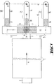
- FIG. 1 shows a melting tank 1, to which an insertion opening 2, which is designed in a conventional manner as a "dog house", and a passage 3 through which the glass melt is withdrawn from the melting tank are shown.
- the glass formers which can consist of the usual batch and broken glass, as well as the glass formed from them, migrate through the melting tank in the direction of arrow 4. It is of course also possible to arrange several insertion openings on the two long sides of the melting tank, which results in a different flow pattern .
- a so-called “riser” can also belong to the passage 3. Such details are state of the art, so that this will not be discussed in more detail.
- a distribution channel 5 which can also be designed as a work tub.
- a distribution channel 5 can also be designed as a work tub.
- Two treatment sections 9 and 10 are formed on both sides of the center line MM, to which the two cooling zones 6 and 7 and possibly also the area 8 belong.
- the remaining flow path of the glass melt forms then a respective homogenization zone 11 and 12.
- homogenization of the temperature distribution is brought about.
- the total length of the forehearths 13, 14 and 15 forms a treatment section 16.
- a cooling zone 17, 18 and 19 which is shown hatched and is surrounded by dashed lines. It is emphasized that the illustration is extremely schematic in order to facilitate understanding.
- a homogenization zone 20, 21 and 22 also adjoins the respective cooling zone in the area of the treatment sections 16.
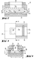
- FIGS. 2, 3 and 4 show in different views and sections a cooling zone K, which at the locations of the cooling zones 6 and 7 in the distribution channel 5 and possibly additionally at the locations of the cooling zones 17, 18 and 19 in the forehearths 13, 14 and 15 can be used.
- the cooling zones in question represent, as it were, a section of a channel with a bottom 23, side walls 24 and a ceiling 25.
- the glass melt enters on the entry side 26 and exits again on the exit side 27.
- closure elements 29 are arranged above the opening, through which the free cross section of the opening 28 can be determined.
- the opening and closing movement is indicated by arrows.
- the two side walls 24 there are two rows of burners 30 (FIG. 4), the mouths of which are accommodated in so-called nozzle stones 31.
- the nozzle stones For the exit of the fuel gases, the nozzle stones have openings 31a which can be seen in FIG. 2 as semicircles because approximately the upper half is covered by ribs which extend downward from the ceiling 25, as is shown approximately in FIG.
- Figures 2 and 3 show that the bottom 23 is provided on a length which approximately corresponds to the length of the opening 28, with an elevation 23a which extends over the entire width B of the channel cross section.
- the elevation 23a forms a threshold, so to speak, which at both ends (seen in the direction of flow) merges into the lower floor level 23c via inclined surfaces 23b. It can clearly be seen that the glass flow 32 in the region of the elevation 23a is reduced to the very flat flow cross section, which enables the high cooling rate.
- the respective homogenization zone then adjoins the exit side 27.
- FIG. 5 shows a variant of the cooling zone K, in which a recess 33 in the ceiling 25 is closed by a plate 34, which in this case represents the radiation receiver for the thermal radiation of the glass stream 32.
- a plate 34 which in this case represents the radiation receiver for the thermal radiation of the glass stream 32.
- Above the plate 34 there is a structure 35 with a U-shaped flow channel 36 for the passage of cooling air.
- the inlet end 36a and outlet end 36b of the flow channel 36 are directed upwards; the direction of flow is indicated by arrows.
- the temperature of the plate 34 is influenced by a corresponding amount of cooling air and thus the cooling effect acting on the glass stream 32.
- the distribution channel 5 shown in section in FIG. 6 has - more clearly drawn than in FIG. 1 - the two cooling zones 6 and 7, which in principle correspond to the cooling zone according to FIGS. 2 to 4.
- the ceiling 25 which is part of the so-called upper furnace, there are the two openings 28 for the energy dissipation by radiation, the extent of the energy dissipation in the manner already described by the displaceable closure elements 29 is adjustable.
- the passage 3 shown in FIG. 1 opens into the bottom 5a of the distribution channel 5, so that there is a riser 5b in the said bottom.
- the base 5a has a ramp-shaped course.
- the already described threshold-shaped elevations 23a protrude from the bottom 5a, which form the flow cross-section according to the invention with a small bath depth between their flat and horizontal tops and the melt level S. Beyond the threshold-shaped elevations 23a, the distribution channel 5 again has a significantly greater depth, so that the undesirable formation of an excessive flow gradient does not occur.
- the foreheads 13, 14 and 15 shown in FIG. 1 are only indicated by their end faces. The direction of movement of the closure elements 29 is rotated by 90 ° with respect to that according to FIG. 4, but this has no influence on the function and effectiveness.
- two threshold-shaped elevations 23a extend from the base 5a, which are likewise delimited by flat and horizontal surfaces which lie below the openings 28.
- the base 5a is again at a significantly greater distance from the melt level S.
- the figure 7 is to be evaluated to scale.
- the so-called "riser” lies at a distance to the right outside of the section of the distribution channel 5 'shown in FIG. 7.
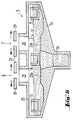
- the exemplary embodiment according to FIGS. 8, 9 and 10 differs from the previously described exemplary embodiments in that the elevation 23a of the base 23 is followed by a further region, in which the geometric conditions are otherwise the same as in FIGS. 2, 3 and 4, in which An immersion cooler 37 is located above the lower floor level 23c and can be acted upon by a cooling medium via two vertical flow channels 38.
- the flow channels 38 can also be designed as concentric pipes, which but is not shown in detail.
- the intensity of the cooling can also be increased by a periodic transverse movement (transverse to the glass flow). Combined movements of the immersion cooler are also possible. It is also easily possible to design the immersion cooler 37 as a pronounced stirring element in order to bring about an additional homogenization of the temperature in the glass stream.
- the flow channels 38 are guided through an opening 40 in the ceiling 25 to the outside.
- the diagram according to FIG. 11 shows values which were partly measured in the exemplary embodiment according to FIG. 7 and partly calculated for comparison purposes.
- the abscissa shows the distance in meters from the center of the riser to the forehead 13, and the ordinate shows the different temperature profiles in ° C.
- the height profile or the topography of the trough bottom with the two elevations 23a is located under the abscissa, albeit in a mirror-symmetrical exchange.
- T 1 is the temperature in the area of the riser
- T 2 is the temperature at the entrance to the forehead 13.
- the curve 41 shows a temperature profile as it would occur without any additional cooling measure, ie due to the usual and inevitable losses due to the finite effect of all insulation measures .
- the curves 42 and 43 show two curves that would occur if the glass melt ran through the two cooling zones in the region of the openings 28 without the presence of the two elevations 23a.
- the lower curve 42 then stands for the surface temperature
- the upper curve 43 stands for the bottom temperature of the melt.
- the large and increasing distance between the two curves 42 and 43 is due to the fact that the bottom region of the melt is exposed to the cooling influence of the openings 28 significantly less than the surface of the melt. It follows from the relationships described at the beginning that the conditions become more unfavorable the more the glass is colored. In the case of colored glasses, both curves 42 and 43 would additionally shift upward, ie even an average temperature formed by homogenization would be significantly higher than the exit temperature T 2 aimed for with the device according to the invention. It results in particular from the large distance between the two curves 42 and 43 at the end of the flow path shown in FIG. 11 that an enormously long homogenization section would be required and intensive measures for homogenization would have to be carried out in order to significantly reduce the temperature
- the further curves 44 and 45 show the conditions when the two threshold-shaped elevations 23a are present in the topography representation below the abscissa in FIG. 11. Due to the small bath depth above the elevations 23a, the bottom region of the melt participates much more strongly in the energy exchange with the surroundings , and in particular it does not release energy to the surface of the melt to the same extent. As a result of this and due to the mixing of the melt in the flow areas above the elevations 23a, the temperature difference is drastically reduced over the entire length of the distributor channel shown and is limited to the area shown by hatching. The line drawn in the center of this area shows the arithmetically determined mean values of the temperature curve. It also follows from FIG. 11 that the small temperature difference at the end of the treatment section in the distribution channel requires a much shorter homogenization section in order to bring the desired approximation of the upper and lower limit temperatures to the mean value.
- the flow cross section over the or each elevation 23a ie the product of bath depth T and width B, is predetermined by the throughput and the average flow velocity.
- the width of the or everyone Opening 28, seen transversely to the direction of flow, is smaller than the width B of the flow cross section, since the two edge regions of the glass flow must be protected against inadmissible cooling, for which purpose a generally relatively weak edge heating, preferably by a burner, is carried out.
- FIG. 11 provides the basis for determining the length of the cooling zone or cooling zones in the flow direction: inlet temperature T 1 and outlet temperature T 2 are due to the upstream melting tank on the one hand and by the subsequent units such as feeders and forehearths otherwise specified. The slight temperature drops outside the cooling zones are also fixed due to known relationships. It can be seen in FIG.
- FIG. 7 shows geometrical design data of such a system that has proven itself to scale.
- the overall context also shows that it is extremely important to place the most intensive part of the cooling zone at the beginning of the treatment section, if possible, in the case of distribution channels or working tanks, as close as possible to the passage of the melting tank.
Landscapes
- Chemical & Material Sciences (AREA)
- Engineering & Computer Science (AREA)
- Materials Engineering (AREA)
- Organic Chemistry (AREA)
- Physics & Mathematics (AREA)
- Thermal Sciences (AREA)
- Glass Compositions (AREA)
- Re-Forming, After-Treatment, Cutting And Transporting Of Glass Products (AREA)
- Physical Or Chemical Processes And Apparatus (AREA)
Claims (20)
- Procédé pour le conditionnement et l'homogénéisation d'un courant de verre (32) s'écoulant en continu dans une ligne de traitement (9, 10, 16) qui s'étend depuis le côté de l'entrée (26) d'une cuve de travail ou d'un canal de répartition (5) jusqu'au moins une position de prélèvement (E) et dans laquelle se trouve au moins une zone de refroidissement (K; 6, 7, 8; 17, 18, 19) à laquelle se raccorde au moins une zone d'homogénéisation (11, 12; 20, 21, 22) pour la température du verre, procédé dans lequel, dans la cuve de travail ou dans le canal de répartition (5), la température s'abaisse, d'une température d'entrée T1, à une température de sortie T2, de préférence pour la fabrication d'objets en verre moulé comme des objets en verre creux et des objets en verre filé, caractérisé par le fait que, dans la zone de refroidissement, dont il y a au moins une, (K; 6, 7, 8), de la cuve de travail ou du canal de répartition (5), au moyen d'au moins une éminence (23a) qui s'élève depuis le fond, on donne à une section de l'écoulement de la masse de verre un rapport profondeur/largeur T/B de valeur maximale 0,6, la profondeur maximale Tmax valant 300 mm, et que, dans le courant de verre (32), au moins 50% de la différence de température entre T1 et T2 sont éliminés dans le total de toutes les zones de refroidissement de la cuve de travail ou du canal de répartition (5).
- Procédé selon la revendication 1, caractérisé par le fait que dans la, ou dans chaque, zone de refroidissement, on donne à une section de l'écoulement de la masse de verre un rapport profondeur/largeur T/B d'une valeur maximale de 0,5.
- Procédé selon la revendication 1, caractérisé par le fait que dans la, ou dans chaque, zone de refroidissement, on donne à une section de l'écoulement de la masse de verre un rapport profondeur/largeur T/B d'une valeur maximale de 0,4.
- Procédé selon la revendication 1, caractérisé par le fait que dans la, ou dans chaque, zone de refroidissement, on donne à une section de l'écoulement de la masse de verre un rapport profondeur/largeur T/B d'une valeur maximale de 0,3.
- Procédé selon la revendication 1, caractérisé par le fait que dans la, ou dans chaque, zone de refroidissement, on donne àune section de l'écoulement de la masse de verre est prescrite avec un rapport profondeur/largeur T/B d'une valeur maximale de 0,2.
- Procédé selon la revendication 1, caractérisé par le fait que la profondeur maximale Tmax vaut 250 mm.
- Procédé selon la revendication 1, caractérisé par le fait que la profondeur maximale Tmax vaut 200 mm.
- Procédé selon la revendication 1, caractérisé par le fait que dans le courant de verre, au moins 60% de la différence de température entre T1 et T2 sont éliminés dans le total de toutes les zones de refroidissement.
- Procédé selon la revendication 1, caractérisé par le fait que dans le courant de verre, au moins 70% de la différence de température entre T1 et T2 sont éliminés dans le total de toutes les zones de refroidissement.
- Appareil pour la mise en oeuvre du procédé selon la revendication 1, comportant une ligne de traitement (9, 10, 16) pour le guidage continu d'un courant de verre (32), qui s'étend depuis le côté de l'entrée (26) d'une cuve de travail ou d'un canal de répartition (5) jusqu'au moins une position de prélèvement (E) et dans laquelle se trouve au moins une zone de refroidissement (K; 6, 7, 8; 17, 18, 19), à laquelle se raccorde au moins une zone d'homogénéisation (11, 12; 20, 21, 22), caractérisé par le fait que dans la zone de refroidissement ,dont il y a au moins une, (K; 6, 7, 8), de la cuve de travail ou du canal de répartition (5), au moyen d'au moins une éminence (23a) qui s'élève depuis le fond pour le courant de verre (32), il y a une section d'écoulement d'un rapport profondeur/largeur T/B de valeur maximale de 0,6, la profondeur maximale Tmax valant 300 mm.
- Appareil selon la revendication 10, caractérisé par le fait que dans la, ou dans chaque, zone de refroidissement, il y a, au-dessus de l'éminence (23a), une section de l'écoulement de la masse de verre d'un rapport profondeur/largeur T/B d'une valeur maximale 0,5.
- Appareil selon la revendication 10, caractérisé par le fait que dans la, ou dans chaque, zone de refroidissement, il y a, au-dessus de l'éminence (23a), une section de l'écoulement de la masse de verre d'un rapport profondeur/largeur T/B d'une valeur maximale 0,4.
- Appareil selon la revendication 10, caractérisé par le fait que dans la, ou dans chaque, zone de refroidissement, il y a, au-dessus de l'éminence (23a), une section de l'écoulement de la masse de verre d'un rapport profondeur/largeur T/B d'une valeur maximale 0,3.
- Appareil selon la revendication 10, caractérisé par le fait que dans la, ou dans chaque, zone de refroidissement, il y a, au-dessus de l'éminence (23a), une section de l'écoulement de la masse de verre d'un rapport profondeur/largeur T/B d'une valeur maximale 0,2.
- Appareil selon la revendication 10, caractérisé par le fait que la profondeur maximale Tmax vaut 250 mm.
- Appareil selon la revendication 10, caractérisé par le fait que la profondeur maximale Tmax vaut 200 mm.
- Appareil selon la revendication 10, caractérisé par le fait que derrière l'éminence (23a), dans le sens de l'écoulement, est disposé un plongeur de refroidissement (37).
- Appareil selon la revendication 17, caractérisé par le fait que le plongeur de refroidissement (37) est disposé avec un mouvement de monte et baisse.
- Appareil selon la revendication 17, caractérisé par le fait que le plongeur de refroidissement (37) est disposé avec possibilité de coulisser périodiquement, horizontalement et transversalement à la direction de l'écoulement.
- Appareil selon la revendication 17, caractérisé par le fait que le plongeur de refroidissement (37) est conçu sous forme d'un agitateur.
Applications Claiming Priority (4)
| Application Number | Priority Date | Filing Date | Title |
|---|---|---|---|
| DE4319773 | 1993-06-15 | ||
| DE4319773 | 1993-06-15 | ||
| DE4411038A DE4411038C2 (de) | 1993-06-15 | 1994-03-30 | Verfahren und Vorrichtung zum Konditionieren und Homogenisieren eines Glasstroms |
| DE4411038 | 1994-03-30 |
Publications (3)
| Publication Number | Publication Date |
|---|---|
| EP0631991A2 EP0631991A2 (fr) | 1995-01-04 |
| EP0631991A3 EP0631991A3 (fr) | 1995-05-03 |
| EP0631991B1 true EP0631991B1 (fr) | 1997-02-05 |
Family
ID=25926782
Family Applications (1)
| Application Number | Title | Priority Date | Filing Date |
|---|---|---|---|
| EP94108596A Expired - Lifetime EP0631991B1 (fr) | 1993-06-15 | 1994-06-06 | Procédé et appareil pour le conditionnement et l'homogénéisation d'un courant de verre |
Country Status (4)
| Country | Link |
|---|---|
| EP (1) | EP0631991B1 (fr) |
| AT (1) | ATE148679T1 (fr) |
| CA (2) | CA2122860C (fr) |
| ES (1) | ES2097575T3 (fr) |
Family Cites Families (6)
| Publication number | Priority date | Publication date | Assignee | Title |
|---|---|---|---|---|
| US1845824A (en) * | 1928-04-18 | 1932-02-16 | Hartford Empire Co | Apparatus for conducting molten glass |
| US1986575A (en) * | 1932-04-05 | 1935-01-01 | Hartford Empire Co | Apparatus for and method of delivering molten glass |
| US3133803A (en) * | 1961-01-16 | 1964-05-19 | Owens Illinois Glass Co | Method and apparatus for conditioning molten glass |
| US3248203A (en) * | 1961-10-30 | 1966-04-26 | Owens Corning Fiberglass Corp | Apparatus for heat control of forehearths |
| US3645712A (en) * | 1970-05-06 | 1972-02-29 | Corning Glass Works | Radiation target structure and use to cool molten glass |
| SE462337B (sv) * | 1986-06-06 | 1990-06-11 | Moss Glasvaerk As | Foerhaerd foer transport av smaelt glas |
-
1994
- 1994-05-04 CA CA002122860A patent/CA2122860C/fr not_active Expired - Fee Related
- 1994-06-06 ES ES94108596T patent/ES2097575T3/es not_active Expired - Lifetime
- 1994-06-06 EP EP94108596A patent/EP0631991B1/fr not_active Expired - Lifetime
- 1994-06-06 AT AT94108596T patent/ATE148679T1/de not_active IP Right Cessation
- 1994-06-15 CA CA002125929A patent/CA2125929C/fr not_active Expired - Fee Related
Also Published As
| Publication number | Publication date |
|---|---|
| ATE148679T1 (de) | 1997-02-15 |
| EP0631991A2 (fr) | 1995-01-04 |
| CA2122860A1 (fr) | 1994-12-16 |
| ES2097575T3 (es) | 1997-04-01 |
| CA2122860C (fr) | 1999-06-22 |
| EP0631991A3 (fr) | 1995-05-03 |
| CA2125929A1 (fr) | 1994-12-16 |
| CA2125929C (fr) | 1999-11-02 |
Similar Documents
| Publication | Publication Date | Title |
|---|---|---|
| DE69418816T2 (de) | Kanal zum Transportieren und Konditionieren von geschmolzenem Glas | |
| DE2603561C2 (de) | Glasschmelzbehälter | |
| EP2391586B1 (fr) | Dispositif de fusion pour la production d'un bain de verre | |
| DE4327237C1 (de) | Verfahren zum Schmelzen von Glas in einem Wannenofen und Wannenofen hierfür | |
| DE3249070C2 (de) | Vorherd zur Verwendung bei der Glasherstellung | |
| DE202018105160U1 (de) | Schmelzraum eines kontinuierlichen Glassschmelzofens und nach einem darin ausgeführtem Verfahren erhaltene Glasschmelze | |
| DE1471832B2 (de) | Verfahren und Vorrichtung zum Homogenisieren von geschmolzenem Glas | |
| DE69023264T2 (de) | Verfahren und Vorrichtung zum Läutern von Glasschmelze. | |
| EP0864543B1 (fr) | Procédé et four de fusion de verre pour la fabrication de verres à haute température de fusion et à composants vaporisables | |
| DE102013203624A1 (de) | Vorrichtung und Verfahren zum Abziehen einer Oberflächenglasschicht und Glaswanne oder -rinne mit einer solchen Vorrichtung | |
| DE69601339T2 (de) | Verfahren und Vorrichtung zum Homogenisieren von geschmolzenem Glas durch Rühren | |
| DE1596539B2 (de) | Vorrichtung zur Herstellung von Tafelglas | |
| DE2722627A1 (de) | Verfahren und vorrichtung zur herstellung von float-glas | |
| EP0631991B1 (fr) | Procédé et appareil pour le conditionnement et l'homogénéisation d'un courant de verre | |
| DE3407697C2 (fr) | ||
| DE2743289C3 (de) | Vorrichtung zum Mischen und Homogenisieren von geschmolzenem Glas in einem Vorherd | |
| DE2317239A1 (de) | Verfahren zum stillsetzen und warten einer mineralische faeden ausziehenden vorrichtung und vorrichtung zur durchfuehrung desselben | |
| DE4411038C2 (de) | Verfahren und Vorrichtung zum Konditionieren und Homogenisieren eines Glasstroms | |
| DE3132111C2 (fr) | ||
| EP0631992B1 (fr) | Procédé et appareil pour le conditionnement et l'homogénéisation d'un courant de verre | |
| DE1421756C3 (de) | Wannenofen zum Erschmelzen von kontinuierlich zu dünnen Faden auszuziehendem Glas | |
| DE3017374C1 (de) | Vorrichtung zur Herstellung von Glasfasern | |
| DE69205058T2 (de) | Verfahren und Vorrichtung zum Erreichen der gewünschten Temperatur eines Glasstromes in einem Speiserkanal. | |
| DE2302200A1 (de) | Verfahren und vorrichtung zur herstellung von flachglas | |
| DE1471835A1 (de) | Vorrichtung zur Herstellung von Flachglas |
Legal Events
| Date | Code | Title | Description |
|---|---|---|---|
| PUAI | Public reference made under article 153(3) epc to a published international application that has entered the european phase |
Free format text: ORIGINAL CODE: 0009012 |
|
| AK | Designated contracting states |
Kind code of ref document: A2 Designated state(s): AT BE CH DE DK ES FR GB IT LI NL PT |
|
| PUAL | Search report despatched |
Free format text: ORIGINAL CODE: 0009013 |
|
| AK | Designated contracting states |
Kind code of ref document: A3 Designated state(s): AT BE CH DE DK ES FR GB IT LI NL PT |
|
| 17P | Request for examination filed |
Effective date: 19950929 |
|
| 17Q | First examination report despatched |
Effective date: 19951102 |
|
| GRAG | Despatch of communication of intention to grant |
Free format text: ORIGINAL CODE: EPIDOS AGRA |
|
| GRAH | Despatch of communication of intention to grant a patent |
Free format text: ORIGINAL CODE: EPIDOS IGRA |
|
| GRAH | Despatch of communication of intention to grant a patent |
Free format text: ORIGINAL CODE: EPIDOS IGRA |
|
| GRAA | (expected) grant |
Free format text: ORIGINAL CODE: 0009210 |
|
| ITF | It: translation for a ep patent filed | ||
| AK | Designated contracting states |
Kind code of ref document: B1 Designated state(s): AT BE CH DE DK ES FR GB IT LI NL PT |
|
| PG25 | Lapsed in a contracting state [announced via postgrant information from national office to epo] |
Ref country code: NL Free format text: LAPSE BECAUSE OF FAILURE TO SUBMIT A TRANSLATION OF THE DESCRIPTION OR TO PAY THE FEE WITHIN THE PRESCRIBED TIME-LIMIT Effective date: 19970205 Ref country code: DK Effective date: 19970205 |
|
| REF | Corresponds to: |
Ref document number: 148679 Country of ref document: AT Date of ref document: 19970215 Kind code of ref document: T |
|
| REG | Reference to a national code |
Ref country code: CH Ref legal event code: NV Representative=s name: KEMENY AG PATENTANWALTBUERO Ref country code: CH Ref legal event code: EP |
|
| GBT | Gb: translation of ep patent filed (gb section 77(6)(a)/1977) |
Effective date: 19970211 |
|
| REF | Corresponds to: |
Ref document number: 59401747 Country of ref document: DE Date of ref document: 19970320 |
|
| REG | Reference to a national code |
Ref country code: ES Ref legal event code: FG2A Ref document number: 2097575 Country of ref document: ES Kind code of ref document: T3 |
|
| REG | Reference to a national code |
Ref country code: PT Ref legal event code: SC4A Free format text: AVAILABILITY OF NATIONAL TRANSLATION Effective date: 19970207 |
|
| ET | Fr: translation filed | ||
| NLV1 | Nl: lapsed or annulled due to failure to fulfill the requirements of art. 29p and 29m of the patents act | ||
| PLBE | No opposition filed within time limit |
Free format text: ORIGINAL CODE: 0009261 |
|
| STAA | Information on the status of an ep patent application or granted ep patent |
Free format text: STATUS: NO OPPOSITION FILED WITHIN TIME LIMIT |
|
| 26N | No opposition filed | ||
| REG | Reference to a national code |
Ref country code: GB Ref legal event code: IF02 |
|
| PGFP | Annual fee paid to national office [announced via postgrant information from national office to epo] |
Ref country code: PT Payment date: 20070423 Year of fee payment: 14 |
|
| PGFP | Annual fee paid to national office [announced via postgrant information from national office to epo] |
Ref country code: ES Payment date: 20070611 Year of fee payment: 14 |
|
| PGFP | Annual fee paid to national office [announced via postgrant information from national office to epo] |
Ref country code: AT Payment date: 20070619 Year of fee payment: 14 |
|
| PGFP | Annual fee paid to national office [announced via postgrant information from national office to epo] |
Ref country code: BE Payment date: 20070627 Year of fee payment: 14 |
|
| PGFP | Annual fee paid to national office [announced via postgrant information from national office to epo] |
Ref country code: DE Payment date: 20070728 Year of fee payment: 14 |
|
| PGFP | Annual fee paid to national office [announced via postgrant information from national office to epo] |
Ref country code: GB Payment date: 20070517 Year of fee payment: 14 Ref country code: CH Payment date: 20070724 Year of fee payment: 14 |
|
| PGFP | Annual fee paid to national office [announced via postgrant information from national office to epo] |
Ref country code: IT Payment date: 20070515 Year of fee payment: 14 |
|
| PGFP | Annual fee paid to national office [announced via postgrant information from national office to epo] |
Ref country code: FR Payment date: 20070418 Year of fee payment: 14 |
|
| REG | Reference to a national code |
Ref country code: PT Ref legal event code: MM4A Free format text: LAPSE DUE TO NON-PAYMENT OF FEES Effective date: 20081209 |
|
| BERE | Be: lapsed |
Owner name: BETEILIGUNGEN *SORG G.M.B.H. & CO. K.G. Effective date: 20080630 |
|
| PG25 | Lapsed in a contracting state [announced via postgrant information from national office to epo] |
Ref country code: PT Free format text: LAPSE BECAUSE OF NON-PAYMENT OF DUE FEES Effective date: 20081209 |
|
| REG | Reference to a national code |
Ref country code: CH Ref legal event code: PL |
|
| GBPC | Gb: european patent ceased through non-payment of renewal fee |
Effective date: 20080606 |
|
| PG25 | Lapsed in a contracting state [announced via postgrant information from national office to epo] |
Ref country code: BE Free format text: LAPSE BECAUSE OF NON-PAYMENT OF DUE FEES Effective date: 20080630 |
|
| REG | Reference to a national code |
Ref country code: FR Ref legal event code: ST Effective date: 20090228 |
|
| PG25 | Lapsed in a contracting state [announced via postgrant information from national office to epo] |
Ref country code: DE Free format text: LAPSE BECAUSE OF NON-PAYMENT OF DUE FEES Effective date: 20090101 Ref country code: AT Free format text: LAPSE BECAUSE OF NON-PAYMENT OF DUE FEES Effective date: 20080606 |
|
| PG25 | Lapsed in a contracting state [announced via postgrant information from national office to epo] |
Ref country code: LI Free format text: LAPSE BECAUSE OF NON-PAYMENT OF DUE FEES Effective date: 20080630 Ref country code: GB Free format text: LAPSE BECAUSE OF NON-PAYMENT OF DUE FEES Effective date: 20080606 Ref country code: CH Free format text: LAPSE BECAUSE OF NON-PAYMENT OF DUE FEES Effective date: 20080630 |
|
| REG | Reference to a national code |
Ref country code: ES Ref legal event code: FD2A Effective date: 20080607 |
|
| PG25 | Lapsed in a contracting state [announced via postgrant information from national office to epo] |
Ref country code: IT Free format text: LAPSE BECAUSE OF NON-PAYMENT OF DUE FEES Effective date: 20080606 Ref country code: FR Free format text: LAPSE BECAUSE OF NON-PAYMENT OF DUE FEES Effective date: 20080630 |
|
| PG25 | Lapsed in a contracting state [announced via postgrant information from national office to epo] |
Ref country code: ES Free format text: LAPSE BECAUSE OF NON-PAYMENT OF DUE FEES Effective date: 20080607 |