EP0631991B1 - Method and apparatus for conditioning and homogenising a glass stream - Google Patents
Method and apparatus for conditioning and homogenising a glass stream Download PDFInfo
- Publication number
- EP0631991B1 EP0631991B1 EP94108596A EP94108596A EP0631991B1 EP 0631991 B1 EP0631991 B1 EP 0631991B1 EP 94108596 A EP94108596 A EP 94108596A EP 94108596 A EP94108596 A EP 94108596A EP 0631991 B1 EP0631991 B1 EP 0631991B1
- Authority
- EP
- European Patent Office
- Prior art keywords
- glass
- section
- depth
- temperature
- flow
- Prior art date
- Legal status (The legal status is an assumption and is not a legal conclusion. Google has not performed a legal analysis and makes no representation as to the accuracy of the status listed.)
- Expired - Lifetime
Links
- 239000011521 glass Substances 0.000 title claims abstract description 127
- 230000003750 conditioning effect Effects 0.000 title claims abstract description 9
- 238000000034 method Methods 0.000 title claims description 20
- 238000001816 cooling Methods 0.000 claims abstract description 106
- 238000009826 distribution Methods 0.000 claims description 45
- 238000000265 homogenisation Methods 0.000 claims description 30
- 230000008569 process Effects 0.000 claims description 15
- 238000007654 immersion Methods 0.000 claims description 8
- 238000004519 manufacturing process Methods 0.000 claims description 8
- 238000003756 stirring Methods 0.000 claims description 6
- 239000005401 pressed glass Substances 0.000 claims description 2
- 230000000694 effects Effects 0.000 abstract description 14
- 230000001143 conditioned effect Effects 0.000 abstract description 2
- 230000000630 rising effect Effects 0.000 abstract description 2
- 238000002844 melting Methods 0.000 description 29
- 230000008018 melting Effects 0.000 description 29
- 230000005855 radiation Effects 0.000 description 20
- 239000000155 melt Substances 0.000 description 13
- 239000000156 glass melt Substances 0.000 description 11
- 238000010438 heat treatment Methods 0.000 description 8
- 238000012545 processing Methods 0.000 description 8
- 230000015572 biosynthetic process Effects 0.000 description 6
- 239000010410 layer Substances 0.000 description 6
- 238000010276 construction Methods 0.000 description 4
- 210000001061 forehead Anatomy 0.000 description 4
- 239000000203 mixture Substances 0.000 description 4
- 230000001419 dependent effect Effects 0.000 description 3
- 238000010586 diagram Methods 0.000 description 3
- 238000000605 extraction Methods 0.000 description 3
- 238000009413 insulation Methods 0.000 description 3
- XEEYBQQBJWHFJM-UHFFFAOYSA-N Iron Chemical compound [Fe] XEEYBQQBJWHFJM-UHFFFAOYSA-N 0.000 description 2
- 239000013078 crystal Substances 0.000 description 2
- 238000013461 design Methods 0.000 description 2
- 238000004031 devitrification Methods 0.000 description 2
- 238000003780 insertion Methods 0.000 description 2
- 230000037431 insertion Effects 0.000 description 2
- 230000021715 photosynthesis, light harvesting Effects 0.000 description 2
- 230000009467 reduction Effects 0.000 description 2
- 238000007670 refining Methods 0.000 description 2
- 238000012876 topography Methods 0.000 description 2
- 229910000838 Al alloy Inorganic materials 0.000 description 1
- VYZAMTAEIAYCRO-UHFFFAOYSA-N Chromium Chemical compound [Cr] VYZAMTAEIAYCRO-UHFFFAOYSA-N 0.000 description 1
- 206010037660 Pyrexia Diseases 0.000 description 1
- 241000863032 Trieres Species 0.000 description 1
- 230000003321 amplification Effects 0.000 description 1
- 230000004888 barrier function Effects 0.000 description 1
- 238000007664 blowing Methods 0.000 description 1
- 230000015556 catabolic process Effects 0.000 description 1
- 239000000919 ceramic Substances 0.000 description 1
- 229910052804 chromium Inorganic materials 0.000 description 1
- 239000011651 chromium Substances 0.000 description 1
- 230000002301 combined effect Effects 0.000 description 1
- 239000004035 construction material Substances 0.000 description 1
- 239000002826 coolant Substances 0.000 description 1
- 230000003247 decreasing effect Effects 0.000 description 1
- 238000006731 degradation reaction Methods 0.000 description 1
- 230000003111 delayed effect Effects 0.000 description 1
- 238000011161 development Methods 0.000 description 1
- 230000018109 developmental process Effects 0.000 description 1
- 239000005357 flat glass Substances 0.000 description 1
- 239000002737 fuel gas Substances 0.000 description 1
- 239000007789 gas Substances 0.000 description 1
- 239000003365 glass fiber Substances 0.000 description 1
- 230000012447 hatching Effects 0.000 description 1
- 210000003128 head Anatomy 0.000 description 1
- 229910052500 inorganic mineral Inorganic materials 0.000 description 1
- 239000012774 insulation material Substances 0.000 description 1
- 230000003993 interaction Effects 0.000 description 1
- 229910052742 iron Inorganic materials 0.000 description 1
- -1 iron-chromium-aluminum Chemical compound 0.000 description 1
- 239000007788 liquid Substances 0.000 description 1
- 239000011707 mineral Substances 0.000 description 1
- 238000002156 mixing Methods 0.000 description 1
- 238000003199 nucleic acid amplification method Methods 0.000 description 1
- 230000000737 periodic effect Effects 0.000 description 1
- 230000035699 permeability Effects 0.000 description 1
- 230000001105 regulatory effect Effects 0.000 description 1
- 238000010079 rubber tapping Methods 0.000 description 1
- 230000007480 spreading Effects 0.000 description 1
- 238000003892 spreading Methods 0.000 description 1
- 239000002344 surface layer Substances 0.000 description 1
- 239000010409 thin film Substances 0.000 description 1
- 238000012546 transfer Methods 0.000 description 1
- 238000011144 upstream manufacturing Methods 0.000 description 1
Images


Classifications
-
- C—CHEMISTRY; METALLURGY
- C03—GLASS; MINERAL OR SLAG WOOL
- C03B—MANUFACTURE, SHAPING, OR SUPPLEMENTARY PROCESSES
- C03B5/00—Melting in furnaces; Furnaces so far as specially adapted for glass manufacture
- C03B5/16—Special features of the melting process; Auxiliary means specially adapted for glass-melting furnaces
- C03B5/23—Cooling the molten glass
-
- C—CHEMISTRY; METALLURGY
- C03—GLASS; MINERAL OR SLAG WOOL
- C03B—MANUFACTURE, SHAPING, OR SUPPLEMENTARY PROCESSES
- C03B7/00—Distributors for the molten glass; Means for taking-off charges of molten glass; Producing the gob, e.g. controlling the gob shape, weight or delivery tact
- C03B7/02—Forehearths, i.e. feeder channels
- C03B7/06—Means for thermal conditioning or controlling the temperature of the glass
-
- Y—GENERAL TAGGING OF NEW TECHNOLOGICAL DEVELOPMENTS; GENERAL TAGGING OF CROSS-SECTIONAL TECHNOLOGIES SPANNING OVER SEVERAL SECTIONS OF THE IPC; TECHNICAL SUBJECTS COVERED BY FORMER USPC CROSS-REFERENCE ART COLLECTIONS [XRACs] AND DIGESTS
- Y02—TECHNOLOGIES OR APPLICATIONS FOR MITIGATION OR ADAPTATION AGAINST CLIMATE CHANGE
- Y02P—CLIMATE CHANGE MITIGATION TECHNOLOGIES IN THE PRODUCTION OR PROCESSING OF GOODS
- Y02P40/00—Technologies relating to the processing of minerals
- Y02P40/50—Glass production, e.g. reusing waste heat during processing or shaping
- Y02P40/57—Improving the yield, e-g- reduction of reject rates
Definitions
- the invention relates to a method for conditioning and homogenizing a continuously flowing glass stream in a treatment line, which extends from an inlet side of a work tub or a distribution channel to at least one removal point and in which there is at least one cooling zone, to which at least one homogenization zone for the Glass temperature adjoins, the temperature in the work tub or the distribution channel being lowered from an inlet temperature T 1 to an outlet temperature T 2 , preferably for producing molded glass parts such as hollow glass parts and pressed glass parts.
- the process temperatures when melting glass depend on its composition, the production process and other factors, the temperatures required for processing the glass are generally lower than the melting temperatures during the manufacture of the glass. As a result, the glass must be cooled between its manufacture and processing.
- the cooling of the glass is part of the so-called “conditioning", in which the glass is prepared for processing.
- the conditioning of the glass also includes achieving a degree of thermal homogeneity required for the processing process in question.
- the glass can only be conditioned when the glass has already left the actual melting unit.
- conditioning was at least predominantly carried out in the so-called forehearths or feeders.
- work tub or the distribution channel has been used for conditioning.
- the specific melting performance i.e. the performance related to the area of the melting range, significantly increased.
- the temperature of the glass removed from the melting tank has risen accordingly.
- Other aids that increase the glass temperature at the bottom of the melting tank, such as. B. bubbler or floor heating mostly lead to an increase in the outlet temperature of the glass from the melting tank.
- the glass processing machines have also been continuously developed to increase throughput, among other things. While still in the sixties and seventies machines for the mass production of hollow glasses 6, 8 or 10 stations were provided for two drops each, larger machines today have 12 to 16 stations for two drops each or ten stations for three or four drops each. As a result, the throughput of a single machine has increased considerably.
- the influences described above have resulted in the total amount of heat which has to be removed from the glass after leaving the melting tank and before processing being increased considerably.
- the increase in the throughput of the individual machines has reduced the dwell time of the glass in the parts of the plant downstream of the melting tank. This leads to the contrary fact that a larger amount of heat has to be dissipated within a shorter time. This means that the productivity of the entire line depends very much on the cooling capacity within the treatment line.
- numerous technical problems must be taken into account again.
- the flow of the glass in work tanks and forehearths which generally have the basic shape of a channel, takes place in the form of a laminar flow due to the relatively high viscosity of the glass.
- a speed profile is formed in the glass bath in which the maximum lies approximately in the middle of the flow channel or on the glass surface. Due to the dependence of the viscosity on the temperature of the glass melt, there is an interaction between the glass temperature, the heat losses and the flow rate of the glass. If the speed is reduced locally, the heat losses are increased by increasing the dwell time. This causes the temperature to drop further and the resulting increase in viscosity further reduces the local flow rate.
- the heat transport in the glass bath itself takes place almost exclusively by radiation, whereby the transport speed depends on the composition of the glass.
- the presence of divalent iron or chromium, which are used to color green glass reduces the heat transport in the glass bath compared to, for example, a lime-soda white glass. Analogous conditions also apply to amber glass. As a result, the heat transfer from the lower areas of the glass bath is delayed. However, cooling the lower areas of the glass bath is essential. If the cooling occurs too late When this happens, no effective cooling effect is observed in the lower areas of the glass bath.
- the prior art mainly deals with the cooling of the glass flow in feeders or forehearths, which are generally connected downstream of a distribution channel.
- the bottom of a working trough or a distribution channel (to the forehearths) runs in a ramp shape, so that extremely unfavorable cooling conditions for the melt are present, particularly in the deep part of the working troughs and distribution channels.
- the reason for this can be seen in the fact that at least predominantly energy extraction from a glass melt can or must only take place by radiation, and here the radiation becomes more and more unfavorable with increasing bath depth because the glass above it absorbs the energy again.
- the conditions are particularly unfavorable for amber glass and green glass, which absorb the longer-wave heat radiation to a considerable extent.
- Trier uses a diagram to indicate that the radiation conductivity of brown glass and green glass at a temperature of 1300 ° C is only about 1/4 to 1 / 6 the radiation conductivity of white glass (commercial glass, window glass). This results in significantly deteriorated cooling conditions with increasing bath depth and increasing glass color. In an analogous manner, however, this leads to the formation of an increasingly increasing temperature gradient between the bath surface and the floor area of the bath, so that a forced flow through a slowly flowing, cooler surface layer forms a rapidly flowing, hotter floor layer.
- the invention is therefore based on the object of specifying a method of the type described at the outset, by means of which both a strong cooling effect and a good homogenization effect are produced with a high throughput of the treatment section. As was shown at the beginning, these demands are diametrically opposed to one another.
- the object is achieved in the above-mentioned method according to the invention in that in the at least one cooling zone of the work tub or the distribution channel by means of at least one elevation projecting from the floor, a flow cross section of the glass mass with a depth / width ratio T / B of at most 0.6 is set, the maximum depth T max being 300 mm, and that in the glass flow in the sum of all the cooling zones of the working tub or the distribution channel, at least 50% of the temperature difference between T 1 and T 2 is reduced.
- the invention consists in producing as low a level as possible of the glass melt in the work tub or in the distribution channel in the area of the cooling zone (s) by at least one threshold-like elevation in the area, drawing as much heat as possible in this area of the low level, so that at Given the given length of the entire treatment section, the longest possible homogenization zone is available, in which an equalization of the remaining temperature differences can be brought about.
- the advantages first increase with decreasing depth, then z. B. if the maximum depth T max when arranging the cooling zone in a work tub or in a distribution channel can also be selected to be less than 300 mm, for example 250 mm, 200 mm or less.
- the specified low bath depths are by no means a matter of course for the high throughputs required today. This is opposed by the effect that a gradient dependent on the flow velocity occurs over the length of the cooling zone and the rest of the flow path, and the flow velocity and thus the gradient increase sharply with a smaller bath depth.
- the idea according to the invention is therefore aimed in the direction of "locally limited thin-film cooling", so that it is possible to use the cooling systems known per se to remove extremely large amounts of heat in a relatively short way, ie locally limited to the region of the elevations, in relation to the temperature difference to be placed between T 1 and T 2 .
- the temperature T 1 is that at the outlet of the melting tank or at the entry into the work tank or the distribution channel and the temperature T 2 is the outlet temperature from the work tank or the distribution channel.
- the temperature T 1 is a consequence of the necessary operating conditions in the melting tank and is usually, but by way of example, between 1350 and 1400 ° C.
- the temperature T 1 is generally higher, the higher the throughput or the performance of the melting tank.
- the temperature T 2 is predetermined both by the type of glass and by the processing conditions of the glass droplets usually produced and is generally between 1120 and 1180 ° C. by way of example.
- measures or means known per se can be used for heat removal, such as, for example, floor cooling through cooling channels built into the floor of the treatment section and / or through insulation which is deliberately reduced in the floor area.
- a Surface cooling can be provided, such as by adjustable ceiling openings, and / or by blowing with gases, for example with air and / or by heat sinks, which are arranged above the glass mirror without contact with the glass flow.
- gases for example with air and / or by heat sinks
- Known means can also be provided for the subsequent homogenization of the temperature in the glass melt, such as a correspondingly long homogenization zone with the prerequisite for the most complete possible thermal insulation from the environment, by uncooled stirring elements or guide surfaces, and likewise by slightly heating the melt from above by radiation or within the glass by the electrical glass resistance and corresponding heating electrodes.
- the thin-layer cooling according to the invention in the shortest possible way can achieve that the flow path of the glass mass in the cooling zone is essentially straight, so that so-called “dead” Corners "and additional heating of the glass in these dead corners can be avoided.
- the structure of the or each cooling zone is simplified considerably and the temperature distribution is already largely homogenized in the cooling zone.
- the invention also relates to a device for carrying out the method with a treatment section for continuously guiding a glass stream, which extends from the entry side of a work tub or a distribution channel to at least one removal point and in which there is at least one cooling zone to which at least one homogenization zone is located for the glass temperature.
- such a device is characterized according to the invention in that a flow cross-section with a depth / width ratio T / B of a maximum of 0.6 in the at least one cooling zone of the working trough or the distribution channel by means of at least one elevation for the glass stream rising from the bottom is present, the maximum depth T max being 300 mm.
- the parts shown in section consist of the usual ceramic or mineral furnace construction and insulation materials.
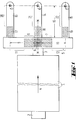
- FIG. 1 shows a melting tank 1, to which an insertion opening 2, which is designed in a conventional manner as a "dog house", and a passage 3 through which the glass melt is withdrawn from the melting tank are shown.
- the glass formers which can consist of the usual batch and broken glass, as well as the glass formed from them, migrate through the melting tank in the direction of arrow 4. It is of course also possible to arrange several insertion openings on the two long sides of the melting tank, which results in a different flow pattern .
- a so-called “riser” can also belong to the passage 3. Such details are state of the art, so that this will not be discussed in more detail.
- a distribution channel 5 which can also be designed as a work tub.
- a distribution channel 5 can also be designed as a work tub.
- Two treatment sections 9 and 10 are formed on both sides of the center line MM, to which the two cooling zones 6 and 7 and possibly also the area 8 belong.
- the remaining flow path of the glass melt forms then a respective homogenization zone 11 and 12.
- homogenization of the temperature distribution is brought about.
- the total length of the forehearths 13, 14 and 15 forms a treatment section 16.
- a cooling zone 17, 18 and 19 which is shown hatched and is surrounded by dashed lines. It is emphasized that the illustration is extremely schematic in order to facilitate understanding.
- a homogenization zone 20, 21 and 22 also adjoins the respective cooling zone in the area of the treatment sections 16.
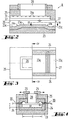
- FIGS. 2, 3 and 4 show in different views and sections a cooling zone K, which at the locations of the cooling zones 6 and 7 in the distribution channel 5 and possibly additionally at the locations of the cooling zones 17, 18 and 19 in the forehearths 13, 14 and 15 can be used.
- the cooling zones in question represent, as it were, a section of a channel with a bottom 23, side walls 24 and a ceiling 25.
- the glass melt enters on the entry side 26 and exits again on the exit side 27.
- closure elements 29 are arranged above the opening, through which the free cross section of the opening 28 can be determined.
- the opening and closing movement is indicated by arrows.
- the two side walls 24 there are two rows of burners 30 (FIG. 4), the mouths of which are accommodated in so-called nozzle stones 31.
- the nozzle stones For the exit of the fuel gases, the nozzle stones have openings 31a which can be seen in FIG. 2 as semicircles because approximately the upper half is covered by ribs which extend downward from the ceiling 25, as is shown approximately in FIG.
- Figures 2 and 3 show that the bottom 23 is provided on a length which approximately corresponds to the length of the opening 28, with an elevation 23a which extends over the entire width B of the channel cross section.
- the elevation 23a forms a threshold, so to speak, which at both ends (seen in the direction of flow) merges into the lower floor level 23c via inclined surfaces 23b. It can clearly be seen that the glass flow 32 in the region of the elevation 23a is reduced to the very flat flow cross section, which enables the high cooling rate.
- the respective homogenization zone then adjoins the exit side 27.
- FIG. 5 shows a variant of the cooling zone K, in which a recess 33 in the ceiling 25 is closed by a plate 34, which in this case represents the radiation receiver for the thermal radiation of the glass stream 32.
- a plate 34 which in this case represents the radiation receiver for the thermal radiation of the glass stream 32.
- Above the plate 34 there is a structure 35 with a U-shaped flow channel 36 for the passage of cooling air.
- the inlet end 36a and outlet end 36b of the flow channel 36 are directed upwards; the direction of flow is indicated by arrows.
- the temperature of the plate 34 is influenced by a corresponding amount of cooling air and thus the cooling effect acting on the glass stream 32.
- the distribution channel 5 shown in section in FIG. 6 has - more clearly drawn than in FIG. 1 - the two cooling zones 6 and 7, which in principle correspond to the cooling zone according to FIGS. 2 to 4.
- the ceiling 25 which is part of the so-called upper furnace, there are the two openings 28 for the energy dissipation by radiation, the extent of the energy dissipation in the manner already described by the displaceable closure elements 29 is adjustable.
- the passage 3 shown in FIG. 1 opens into the bottom 5a of the distribution channel 5, so that there is a riser 5b in the said bottom.
- the base 5a has a ramp-shaped course.
- the already described threshold-shaped elevations 23a protrude from the bottom 5a, which form the flow cross-section according to the invention with a small bath depth between their flat and horizontal tops and the melt level S. Beyond the threshold-shaped elevations 23a, the distribution channel 5 again has a significantly greater depth, so that the undesirable formation of an excessive flow gradient does not occur.
- the foreheads 13, 14 and 15 shown in FIG. 1 are only indicated by their end faces. The direction of movement of the closure elements 29 is rotated by 90 ° with respect to that according to FIG. 4, but this has no influence on the function and effectiveness.
- two threshold-shaped elevations 23a extend from the base 5a, which are likewise delimited by flat and horizontal surfaces which lie below the openings 28.
- the base 5a is again at a significantly greater distance from the melt level S.
- the figure 7 is to be evaluated to scale.
- the so-called "riser” lies at a distance to the right outside of the section of the distribution channel 5 'shown in FIG. 7.
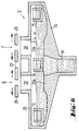
- the exemplary embodiment according to FIGS. 8, 9 and 10 differs from the previously described exemplary embodiments in that the elevation 23a of the base 23 is followed by a further region, in which the geometric conditions are otherwise the same as in FIGS. 2, 3 and 4, in which An immersion cooler 37 is located above the lower floor level 23c and can be acted upon by a cooling medium via two vertical flow channels 38.
- the flow channels 38 can also be designed as concentric pipes, which but is not shown in detail.
- the intensity of the cooling can also be increased by a periodic transverse movement (transverse to the glass flow). Combined movements of the immersion cooler are also possible. It is also easily possible to design the immersion cooler 37 as a pronounced stirring element in order to bring about an additional homogenization of the temperature in the glass stream.
- the flow channels 38 are guided through an opening 40 in the ceiling 25 to the outside.
- the diagram according to FIG. 11 shows values which were partly measured in the exemplary embodiment according to FIG. 7 and partly calculated for comparison purposes.
- the abscissa shows the distance in meters from the center of the riser to the forehead 13, and the ordinate shows the different temperature profiles in ° C.
- the height profile or the topography of the trough bottom with the two elevations 23a is located under the abscissa, albeit in a mirror-symmetrical exchange.
- T 1 is the temperature in the area of the riser
- T 2 is the temperature at the entrance to the forehead 13.
- the curve 41 shows a temperature profile as it would occur without any additional cooling measure, ie due to the usual and inevitable losses due to the finite effect of all insulation measures .
- the curves 42 and 43 show two curves that would occur if the glass melt ran through the two cooling zones in the region of the openings 28 without the presence of the two elevations 23a.
- the lower curve 42 then stands for the surface temperature
- the upper curve 43 stands for the bottom temperature of the melt.
- the large and increasing distance between the two curves 42 and 43 is due to the fact that the bottom region of the melt is exposed to the cooling influence of the openings 28 significantly less than the surface of the melt. It follows from the relationships described at the beginning that the conditions become more unfavorable the more the glass is colored. In the case of colored glasses, both curves 42 and 43 would additionally shift upward, ie even an average temperature formed by homogenization would be significantly higher than the exit temperature T 2 aimed for with the device according to the invention. It results in particular from the large distance between the two curves 42 and 43 at the end of the flow path shown in FIG. 11 that an enormously long homogenization section would be required and intensive measures for homogenization would have to be carried out in order to significantly reduce the temperature
- the further curves 44 and 45 show the conditions when the two threshold-shaped elevations 23a are present in the topography representation below the abscissa in FIG. 11. Due to the small bath depth above the elevations 23a, the bottom region of the melt participates much more strongly in the energy exchange with the surroundings , and in particular it does not release energy to the surface of the melt to the same extent. As a result of this and due to the mixing of the melt in the flow areas above the elevations 23a, the temperature difference is drastically reduced over the entire length of the distributor channel shown and is limited to the area shown by hatching. The line drawn in the center of this area shows the arithmetically determined mean values of the temperature curve. It also follows from FIG. 11 that the small temperature difference at the end of the treatment section in the distribution channel requires a much shorter homogenization section in order to bring the desired approximation of the upper and lower limit temperatures to the mean value.
- the flow cross section over the or each elevation 23a ie the product of bath depth T and width B, is predetermined by the throughput and the average flow velocity.
- the width of the or everyone Opening 28, seen transversely to the direction of flow, is smaller than the width B of the flow cross section, since the two edge regions of the glass flow must be protected against inadmissible cooling, for which purpose a generally relatively weak edge heating, preferably by a burner, is carried out.
- FIG. 11 provides the basis for determining the length of the cooling zone or cooling zones in the flow direction: inlet temperature T 1 and outlet temperature T 2 are due to the upstream melting tank on the one hand and by the subsequent units such as feeders and forehearths otherwise specified. The slight temperature drops outside the cooling zones are also fixed due to known relationships. It can be seen in FIG.
- FIG. 7 shows geometrical design data of such a system that has proven itself to scale.
- the overall context also shows that it is extremely important to place the most intensive part of the cooling zone at the beginning of the treatment section, if possible, in the case of distribution channels or working tanks, as close as possible to the passage of the melting tank.
Landscapes
- Chemical & Material Sciences (AREA)
- Engineering & Computer Science (AREA)
- Materials Engineering (AREA)
- Organic Chemistry (AREA)
- Physics & Mathematics (AREA)
- Thermal Sciences (AREA)
- Glass Compositions (AREA)
- Re-Forming, After-Treatment, Cutting And Transporting Of Glass Products (AREA)
- Physical Or Chemical Processes And Apparatus (AREA)
Abstract
Description
Die Erfindung betrifft ein Verfahren zum Konditionieren und Homogenisieren eines kontinuierlich fließenden Glasstromes in einer Behandlungsstrecke, die sich von einer Eintrittsseite einer Arbeitswanne oder eines Verteilerkanals bis zu mindestens einer Entnahmestelle erstreckt und in der sich mindestens eine Kühlzone befindet, an die sich mindestens eine Homogenisierungszone für die Glastemperatur anschließt, wobei in der Arbeitswanne oder dem Verteilerkanal die Temperatur von einer Eintrittstemperatur T1 auf eine Austrittstemperatur T2 abgesenkt wird, vorzugsweise zum Herstellen von Formglasteilen wie Hohlglasteilen und Preßglasteilen.The invention relates to a method for conditioning and homogenizing a continuously flowing glass stream in a treatment line, which extends from an inlet side of a work tub or a distribution channel to at least one removal point and in which there is at least one cooling zone, to which at least one homogenization zone for the Glass temperature adjoins, the temperature in the work tub or the distribution channel being lowered from an inlet temperature T 1 to an outlet temperature T 2 , preferably for producing molded glass parts such as hollow glass parts and pressed glass parts.
Während die Prozeßtemperaturen beim Erschmelzen von Glas von dessen Zusammensetzung, vom Produktionsverfahren und von anderen Faktoren abhängen, liegen die zur Verarbeitung des Glases erforderlichen Temperaturen in der Regel niedriger als die Schmelztemperaturen bei der Herstellung des Glases. Demzufolge muß das Glas zwischen seiner Herstellung und Verarbeitung abgekühlt werden. Die Abkühlung des Glases ist ein Teil der sogenannten "Konditionierung", bei der das Glas für die Verarbeitung aufbereitet wird. Ebenfalls zur Konditionierung des Glases gehört das Erreichen eines für den in Frage kommenden Verarbeitungsprozeß erforderlichen Grades an thermischer Homogenität.While the process temperatures when melting glass depend on its composition, the production process and other factors, the temperatures required for processing the glass are generally lower than the melting temperatures during the manufacture of the glass. As a result, the glass must be cooled between its manufacture and processing. The cooling of the glass is part of the so-called "conditioning", in which the glass is prepared for processing. The conditioning of the glass also includes achieving a degree of thermal homogeneity required for the processing process in question.
Die Konditionierung des Glases kann erst dann vorgenommen werden, wenn das Glas das eigentliche Schmelzaggregat bereits verlassen hat. Früher wurde die Konditionierung zumindest überwiegend in den sogenannten Vorherden oder Speisern durchgeführt. Seit einiger Zeit wird auch die sogenannte Arbeitswanne oder der Verteilerkanal für die Konditionierung herangezogen. Einige Entwicklungen der allerletzten Zeit haben die Situation in bezug auf das Abkühlen des Glases entscheidend verändert.The glass can only be conditioned when the glass has already left the actual melting unit. In the past, conditioning was at least predominantly carried out in the so-called forehearths or feeders. For some time now, the so-called work tub or the distribution channel has been used for conditioning. Some recent developments have decisively changed the situation regarding the cooling of the glass.
Im Bereich der Schmelzwannen wurde durch verschiedene Maßnahmen die spezifische Schmelzleistung, d.h. die auf die Fläche des Schmelzbereichs bezogene Leistung, wesentlich erhöht. Entsprechend gestiegen ist damit auch die Temperatur des aus der Schmelzwanne abgezogenen Glases. Auch andere Hilfsmittel, durch die die Glastemperatur am Boden der Schmelzwanne erhöht wird, wie z. B. Bubbler oder Bodenheizungen führen meist zu einer Steigerung der Austrittstemperatur des Glases aus der Schmelzwanne.In the area of the melting tanks, the specific melting performance, i.e. the performance related to the area of the melting range, significantly increased. The temperature of the glass removed from the melting tank has risen accordingly. Other aids that increase the glass temperature at the bottom of the melting tank, such as. B. bubbler or floor heating mostly lead to an increase in the outlet temperature of the glass from the melting tank.
Auch die Glas-Verarbeitungsmaschinen wurden ständig weiterentwickelt, um u. a. den Durchsatz zu steigern. Während noch in den Sechziger und Siebziger Jahren Maschinen zur Massenherstellung von Hohlgläsern mit 6, 8 oder 10 Stationen für jeweils zwei Tropfen versehen waren, haben größere Maschinen heutzutage 12 bis 16 Stationen für jeweils zwei Tropfen oder zehn Stationen für jeweils drei oder vier Tropfen. Dadurch hat sich die Durchsatzleistung einer einzelnen Maschine ganz erheblich erhöht. Die vorstehend beschriebenen Einflüsse haben dazu geführt, daß die gesamte Wärmemenge, die dem Glas nach dem Verlassen der Schmelzwanne und vor der Verarbeitung entnommen werden muß, erheblich gestiegen ist. Die Steigerung des Durchsatzes der einzelnen Maschinen hat die Verweilzeit des Glases in den der Schmelzwanne nachgeschalteten Teilen der Anlage verringert. Dies führt zu dem konträren Sachverhalt, daß eine größere Wärmemenge innerhalb einer geringeren Zeit abgeführt werden muß. Daraus ergibt sich, daß die Produktivität der gesamten Linie ganz erheblich von der Kühlleistung innerhalb der Behandlungsstrecke abhängt. Hierbei müssen allerdings erneut zahlreiche technische Probleme beachtet werden.The glass processing machines have also been continuously developed to increase throughput, among other things. While still in the sixties and seventies machines for the mass production of
Das Fließen des Glases in Arbeitswannen und Vorherden, die im allgemeinen die Grundform eines Kanals aufweisen, erfolgt aufgrund der relativ hohen Viskosität des Glases in Form einer laminaren Strömung. Typischerweise bildet sich dabei im Glasbad ein Geschwindigkeitsprofil aus, bei dem das Maximum etwa in der Mitte des Strömungskanals bzw. an der Glasoberfläche liegt. Aufgrund der Abhängigkeit der Viskosität von der Temperatur der Glasschmelze existiert eine Wechselwirkung zwischen der Glastemperatur, den Wärmeverlusten und der Fließgeschwindigkeit des Glases. Bei örtlich herabgesetzter Geschwindigkeit werden die Wärmeverluste durch Erhöhung der Verweilzeit vergrößert. Dadurch sinkt die Temperatur weiter ab, und durch die dadurch bedingte Erhöhung der Viskosität verringert sich die örtliche Fließgeschwindigkeit noch weiter.The flow of the glass in work tanks and forehearths, which generally have the basic shape of a channel, takes place in the form of a laminar flow due to the relatively high viscosity of the glass. Typically, a speed profile is formed in the glass bath in which the maximum lies approximately in the middle of the flow channel or on the glass surface. Due to the dependence of the viscosity on the temperature of the glass melt, there is an interaction between the glass temperature, the heat losses and the flow rate of the glass. If the speed is reduced locally, the heat losses are increased by increasing the dwell time. This causes the temperature to drop further and the resulting increase in viscosity further reduces the local flow rate.
Die Verringerung der Strömungsgeschwindigkeit in einem Bereich führt bei gleichbleibender Durchsatzmenge zwangsläufig zur Erhöhung der Strömungsgeschwindigkeiten in anderen Bereichen mit höheren Glastemperaturen. Damit wiederum wird die Verweilzeit in den Bereichen mit höherer Temperatur und dadurch die effektive Kühlleistung reduziert. Aus diesem Grunde muß die Wirkung eines Kühlsystems möglichst genau definierbar sein, und innerhalb der Kühlzone sollen möglichst Bereiche vermieden werden, in denen geringe Strömungsgeschwindigkeiten auftreten. Durch Bereiche mit niedrigen Temperaturen und höheren Viskositäten tritt wirkungsmäßig eine Verengung des Strömungsquerschnitts ein, was wiederum zu einem erhöhten Gefälle des Glasstandes zwischen der Schmelzwanne und der Entnahmestelle führt. Dies kann wiederum Produktionsstörungen zur Folge haben.The reduction in flow velocity in one area inevitably leads to an increase in flow velocity in other areas with higher throughput rates Glass temperatures. This in turn reduces the dwell time in the areas with a higher temperature and thus the effective cooling capacity. For this reason, the effect of a cooling system must be definable as precisely as possible, and areas within the cooling zone should be avoided wherever possible in which low flow velocities occur. Areas with low temperatures and higher viscosities result in a narrowing of the flow cross section, which in turn leads to an increased gradient of the glass level between the melting tank and the extraction point. This in turn can lead to production disruptions.
Außerdem muß hierbei berücksichtigt werden, daß die Abkühlung von Gläsern bestimmter Zusammensetzung unterhalb bestimmter Grenztemperaturen, die von der Glaszusammensetzung abhängig sind, zur Bildung von Kristallen führen kann, ein Vorgang, der als "Entglasung" bezeichnet wird. Auch dieser Vorgang kann die Produktion empfindlich stören. Infolgedessen ist beim Einsatz einer Kühlstrecke die Abkühlung des Glasbades auf Temperaturen unterhalb der Entglasungstemperatur möglichst zu vermeiden. Da wiederum die Kristallbildung sowohl von der Temperatur als auch von der Zeit abhängig ist, spielt die Verweilzeit des Glases in dem kritischen Temperaturbereich zusätzlich eine wesentliche Rolle.In addition, it must be taken into account here that the cooling of glasses of a certain composition below certain limit temperatures, which depend on the glass composition, can lead to the formation of crystals, a process which is referred to as "devitrification". This process can also seriously disrupt production. As a result, the cooling of the glass bath to temperatures below the devitrification temperature should be avoided if possible when using a cooling section. Since the crystal formation is dependent on both the temperature and the time, the residence time of the glass in the critical temperature range also plays an important role.
Der Wärmetransport im Glasbad selbst findet fast ausschließlich durch Strahlung statt, wobei die Transportgeschwindigkeit von der Zusammensetzung des Glases abhängig ist. Beispielsweise bewirkt die Anwesenheit von zweiwertigem Eisen oder Chrom, die zur Färbung von grünem Glas eingesetzt werden, eine Herabsetzung des Wärmetransports im Glasbad im Vergleich beispielsweise zu einem Kalk-Natron-Weißglas. Analoge Verhältnisse gelten auch für Braunglas. Dies hat zur Folge, daß der Wärmetransport aus den unteren Bereichen des Glasbades verzögert wird. Eine Kühlung der unteren Bereiche des Glasbades ist aber unerläßlich. Erfolgt die Kühlung zu einem zu späten Zeitpunkt, so wird kein effektiver Kühleffekt mehr in den unteren Bereichen des Glasbades beobachtet.The heat transport in the glass bath itself takes place almost exclusively by radiation, whereby the transport speed depends on the composition of the glass. For example, the presence of divalent iron or chromium, which are used to color green glass, reduces the heat transport in the glass bath compared to, for example, a lime-soda white glass. Analogous conditions also apply to amber glass. As a result, the heat transfer from the lower areas of the glass bath is delayed. However, cooling the lower areas of the glass bath is essential. If the cooling occurs too late When this happens, no effective cooling effect is observed in the lower areas of the glass bath.
Es sind zahlreiche Kühlsysteme bekannt geworden, bei denen der Wärmetransport durch Strahlung überwiegt. Diese Art des Wärmeentzugs ist deswegen vorteilhaft, weil dadurch die Wärme nicht unmittelbar von der Glasoberfläche entnommen wird, sondern von einer Schicht, deren Stärke von der Strahlungsdurchlässigkeit des Glases abhängt. Das Stefan-Boltzmann-Gesetz bietet eine Berechnungsgrundlage für die durch Strahlung transportierten Wärmemengen. Ein wesentlicher Faktor ist dabei der Temperaturunterschied zwischen Strahler und Empfänger. In der für die Glasindustrie typischen Anwendung ist die Temperatur des Glases als Strahler vorgegeben. Aus diesem Grunde ist die Temperatur des Empfängers für die abgezogene Wärmemenge ausschlaggebend.Numerous cooling systems have become known in which the heat transport by radiation predominates. This type of heat extraction is advantageous because it does not remove the heat directly from the glass surface, but rather from a layer, the strength of which depends on the radiation permeability of the glass. The Stefan Boltzmann Act provides a basis for calculating the amounts of heat transported by radiation. An important factor is the temperature difference between the radiator and the receiver. In the application typical for the glass industry, the temperature of the glass is specified as the radiator. For this reason, the temperature of the receiver is decisive for the amount of heat drawn off.
Ein effektives Kühlsystem ist in der EP-PS 0 212 539 beschrieben. Hierbei sind in der Decke einer Behandlungsstrecke Öffnungen vorgesehen, deren wirksamer Querschnitt durch verschiebbare Platten veränderbar ist. Dadurch wird die Umgebung nach Maßgabe des Öffnungsquerschnitts als Strahlungsempfänger benutzt. Da die Temperatur der Umgebung auch im ungünstigsten Fall unter 100 °C liegt und damit wesentlich niedriger liegt als die erreichbaren Empfängertemperaturen bei anderen Systemen, ist die Leistungsfähigkeit pro Flächeneinheit wesentlich höher. Andererseits erzeugen aber die Abstrahlungsöffnungen eine Kaminwirkung und verursachen damit wiederum konvektive Luftbewegungen. Solche Bewegungen sind schwer kontrollierbar und können zu regelungstechnischen Problemen führen.An effective cooling system is described in EP-PS 0 212 539. In this case, openings are provided in the ceiling of a treatment line, the effective cross section of which can be changed by means of displaceable plates. As a result, the surroundings are used as radiation receivers in accordance with the opening cross section. Since the ambient temperature is below 100 ° C in the worst case and is therefore significantly lower than the receiver temperatures that can be achieved with other systems, the performance per unit area is significantly higher. On the other hand, however, the radiation openings create a chimney effect and in turn cause convective air movements. Such movements are difficult to control and can lead to control problems.
Auch wenn die vorhandene Kühlkapazität ausreichend ist, kann es immer noch zu Problemen bei der Kühlung der unteren Schichten der Glasströmung kommen, die vor allem bei Farbgläsern eine zu hohe Temperatur behalten.Even if the available cooling capacity is sufficient, there can still be problems with cooling the lower layers of the glass flow, which keep the temperature too high, especially with colored glasses.
Durch die US-A-4 854 960 ist es bekannt, oberhalb der durchbrochenen Decke eines Vorherdes zur Aufnahme der Wärmestrahlung der Glasschmelze Kühlkanäle vorzusehen, die aus einer bestimmten Eisen-Chrom-Aluminium-Legierung bestehen. Ausführungen über die Tiefe des Schmelzbades werden nicht gemacht. Die bekannte Vorrichtung ist für einen verhältnismäßig geringen Glasdurchsatz von 10 bis 60 Tonnen pro Tag vorgesehen. Anregungen für den Bau und Betrieb von Arbeitswannen und Verteilerkanälen sind dieser Schrift nicht zu entnehmen.From US-A-4 854 960 it is known to provide cooling channels, which consist of a specific iron-chromium-aluminum alloy, above the perforated ceiling of a forehearth for receiving the heat radiation from the glass melt. No statements are made about the depth of the weld pool. The known device is intended for a relatively low glass throughput of 10 to 60 tons per day. Suggestions for the construction and operation of work tanks and distribution channels cannot be found in this document.
Durch die US-A-3 133 803 ist es bekannt, am Ende eines Vorherdes unmittelbar vor dem Speiserkopf mit der Entnahmestelle Deckenbeheizungen und Bodenkühlungen vorzusehen, die gemeinsam oder alternativ betrieben werden können. Bei dieser Vorrichtung fehlt jedoch eine nachgeschaltete Homogenisierungszone, so daß sich bei hohem Glasdurchsatz erhebliche Temperaturdifferenzen zwischen der Schmelzenoberfläche und der Bodenströmung einstellen können. Anregungen für den Bau und die Betriebsweise von Arbeitswannen oder Verteilerkanälen sind auch dieser Druckschrift nicht zu entnehmen.From US-A-3 133 803 it is known to provide ceiling heating and floor cooling at the end of a forehearth directly in front of the feeder head with the removal point, which can be operated together or alternatively. In this device, however, there is no downstream homogenization zone, so that considerable temperature differences between the melt surface and the bottom flow can occur with a high glass throughput. This publication does not contain any suggestions for the construction and operation of work tubs or distribution channels.
Durch die US-A-3 248 203 ist es bekannt, über nahezu die gesamte Länge eines Vorherdes in dessen Boden Kühlkörper vorzusehen, die aus dem Boden hervorstehen, parallel zur Strömungsrichtung des Glases verlaufen und die Glasströmung gewissermaßen in zwei Teilströmungen unterteilen. Hiermit ist es zwar möglich, dem Zentrum des Glasstromes eine große Wärmemenge zu entziehen, in Folge des Fehlens einer nachgeschalteten Homogenisierungszone ist es jedoch nicht mehr möglich, große Temperaturgradienten in der Glasschmelze in vertikaler und horizontaler Richtung auszugleichen. Soweit Badtiefen angegeben sind, handelt es sich nur um den Abstand zwischen dem Schmelzenspiegel und der Oberseite der Kühlkörper. Dieser Abstand wird mit beispielhaft 2,54 cm angegeben. Der bekannte Vorherd, der vorzugsweise für die Herstellung von Glasfasern vorgesehen ist, kann keine Anregungen für Bau und Betriebsweise von Arbeitswannen und Verteilerkanälen geben.It is known from US Pat. No. 3,248,203 to provide heat sinks in the bottom of the forehead over almost the entire length thereof, which project from the bottom, run parallel to the direction of flow of the glass and to a certain extent divide the glass flow into two partial flows. Although this makes it possible to extract a large amount of heat from the center of the glass stream, it is no longer possible to compensate for large temperature gradients in the glass melt in the vertical and horizontal directions due to the lack of a downstream homogenization zone. As far as bath depths are given, it is only the distance between the melt level and the top of the heat sink. This distance is given as an example of 2.54 cm. The well-known forehearth, which is preferably intended for the production of glass fibers, cannot provide any suggestions for the construction and operation of work tanks and distribution channels.
Durch die US-PS 2 394 893 ist es bekannt, den recht tiefen Inhalt einer Arbeitswanne mittels eines rechenähnlichen, gekühlten Rührers regelrecht abzurastern und dadurch den Inhalt der Arbeitswanne systematisch umzurühren. Diese Maßnahme ist jedoch konstruktiv sehr aufwendig und führt dennoch nicht zu einer Homogenisierung der Temperaturverteilung, da an den verschiedenen Ausgängen der Arbeitswanne kein hinreichender Strömungsweg für einen Temperaturausgleich mehr vorhanden ist.From US-
Durch die DE-PS 25 07 015 ist es weiterhin bekannt, in der Schmelzwanne selbst, zwischen einem Schmelzabschnitt und einem Läuterungsabschnitt hoher Temperatur einerseits und einer Läuterungszone niedrigerer Temperatur andererseits wassergekühlte Rührvorrichtungen vorzusehen, um die Homogenisierung zu steigern und die Qualität des Glases zu verbessern. Dadurch wird aber eine größere Länge der Schmelzwanne erforderlich, und die Probleme hinsichtlich einer weiteren Kühlung und Homogenisierung der Temperatur in den sich an die Schmelzwanne anschließenden Aggregaten zur Weiterverarbeitung des Glases werden nicht gelöst.From
Der Stand der Technik befaßt sich überwiegend mit der Kühlung der Glasströmung in Speisern oder Vorherden, die in der Regel einem Verteilerkanal nachgeschaltet sind.The prior art mainly deals with the cooling of the glass flow in feeders or forehearths, which are generally connected downstream of a distribution channel.
Durch den Aufsatz von Sims "Increased Conditioning Time Leads to Improved Thermal Homogeneity", veröffentlicht in "GLASS INDUSTRY", November 1991, Seiten 8 bis 15, ist es bekannt, das von Vorherden her bekannte Prinzip der Abstrahlungskühlung durch im Querschnitt geregelte Abstrahlungsöffnungen in der Speiserdecke auch in den Decken von Arbeitswannen einzusetzen, um eine möglichst frühe Kühlung und eine lange Verweilzeit in der Homogenisierungszone erreichen zu können. Die Kühlwirkung ist in diesem Bereich jedoch begrenzt, da in Arbeitswannen und Verteilerkanälen üblicherweise zumindest in der Mitte eine große Badtiefe vorliegt, die auf die Lage des Deep-Refiners und des sich anschließenden Risers zurückzuführen ist. In vielen Fällen verläuft daher der Boden einer Arbeitswanne oder eines Verteilerkanals (zu den Vorherden) rampenförmig, so daß insbesondere im tiefen Teil der Arbeitswannen und Verteilerkanäle außerordentlich ungünstige Abkühlbedingungen für die Schmelze vorliegen. Die Ursache hierfür ist darin zu sehen, daß ein Energieabzug aus einer Glasschmelze zumindest überwiegend nur durch Strahlung erfolgen kann oder muß, und hierbei wird die Abstrahlung mit zunehmender Badtiefe immer ungünstiger, weil das darüber liegende Glas die Energie wieder absorbiert. Die Verhältnisse sind besonders ungünstig bei Braunglas und Grünglas, die die längerwellige Wärmestrahlung in erheblichem Umfange absorbieren. So weist Trier in seinem Buch "Glasschmelzöfen", Springer-Verlag, 1984, auf den Seiten 211/212 anhand eines Diagramms darauf hin, daß die Strahlungsleitfähigkeit von Braunglas und Grünglas bei einer Temperatur von 1300 °C nur etwa 1/4 bis 1/6 der Strahlungsleitfähigkeit von Weißglas (Wirtschaftsglas, Fensterglas) beträgt. Daraus resultieren erheblich verschlechterte Abkühlbedingungen mit zunehmender Badtiefe und zunehmender Glasfärbung. Dies aber führt in analoger Weise zur Ausbildung eines zunehmend steigenden Temperaturgradienten zwischen Badoberfläche und dem Bodenbereich des Bades, so daß sich bei erzwungenem Durchsatz unter einer langsam fließenden kühleren Oberflächenschicht eine schnell fließende heißere Bodenschicht ausbildet. Zum Ausgleich derartiger Vorgänge würden außerordentlich lange Homogenisierungszonen mit entsprechend großer Energiezufuhr benötigt, wobei schon der Platzbedarf nicht befriedigend gelöst werden kann. Wie bereits gesagt werden die Probleme mit zunehmender Färbung des Glases um ein Vielfaches, d.h. um den Faktor 4 bis 6, verschärft.Through the essay by Sims "Increased Conditioning Time Leads to Improved Thermal Homogeneity", published in "GLASS INDUSTRY", November 1991,
Nun könnte man zur Beseitigung des Problems daran denken, die gesamte Badtiefe in der Arbeitswanne oder im Verteilerkanal entsprechend zu verringern, um den negativen "Tiefeneffekt" zu kompensieren. Diese Maßnahme würde aber aufgrund der temperaturabhängigen Viskosität der Schmelze und des in hochviskosen Flüssigkeiten entstehenden Strömungsprofils zur Ausbildung eines Gefälles führen, dessen Höhendifferenz mit zunehmendem Durchsatz steigt, und genau dieser hohe Durchsatz wird bei modernen Glasschmelzanlagen in zunehmendem Maße gefordert. Die Ausbildung eines Gefälles in einer Arbeitswanne oder einem Verteilerkanal ist aber extrem unerwünscht, weil sich dann an den verschiedenen Entnahmestellen nicht mehr die gleichen Parameter einstellen lassen.Now one could think of the entire bath depth in the work tub or in the distribution channel to eliminate the problem decrease accordingly to compensate for the negative "depth effect". However, due to the temperature-dependent viscosity of the melt and the flow profile arising in highly viscous liquids, this measure would lead to the formation of a gradient, the height difference of which increases with increasing throughput, and precisely this high throughput is increasingly required in modern glass melting plants. However, the formation of a gradient in a work tub or a distribution channel is extremely undesirable because the same parameters can then no longer be set at the different tapping points.
Der Erfindung liegt daher die Aufgabe zugrunde, ein Verfahren der eingangs beschriebenen Gattung anzugeben, durch das bei hohem Durchsatz der Behandlungsstrecke sowohl ein starker Kühleffekt als auch ein guter Homogenisierungseffekt erzeugt werden. Wie eingangs aufgezeigt wurde, stehen sich diese Forderungen gewissermaßen diametral entgegen.The invention is therefore based on the object of specifying a method of the type described at the outset, by means of which both a strong cooling effect and a good homogenization effect are produced with a high throughput of the treatment section. As was shown at the beginning, these demands are diametrically opposed to one another.
Die Lösung der gestellten Aufgabe erfolgt bei dem eingangs angegebenen Verfahren erfindungsgemäß dadurch, daß in der mindestens einen Kühlzone der Arbeitswanne oder des Verteilerkanals mittels mindestens einer vom Boden aufragenden Erhebung ein Strömungsquerschnitt der Glasmasse mit einem Tiefen-/Breitenverhältnis T/B von maximal 0,6 eingestellt wird, wobei die maximale Tiefe Tmax 300 mm beträgt, und daß in dem Glasstrom in der Summe aller Kühlzonen der Arbeitswanne oder des Verteilerkanals mindestens 50 % der Temperaturdifferenz zwischen T1 und T2 abgebaut werden.The object is achieved in the above-mentioned method according to the invention in that in the at least one cooling zone of the work tub or the distribution channel by means of at least one elevation projecting from the floor, a flow cross section of the glass mass with a depth / width ratio T / B of at most 0.6 is set, the maximum depth T max being 300 mm, and that in the glass flow in the sum of all the cooling zones of the working tub or the distribution channel, at least 50% of the temperature difference between T 1 and T 2 is reduced.
Vereinfacht ausgedrückt besteht die Erfindung darin, in der Arbeitswanne oder im Verteilerkanal im Bereich der Kühlzone(n) durch mindestens eine schwellenartige Bodenerhebung einen möglichst niedrigen Füllstand der Glasschmelze zu erzeugen, in diesem Bereich des niedrigen Füllstandes möglichst viel Wärme zu entziehen, so daß bei gegebener Länge der gesamten Behandlungsstrecke eine möglichst lange Homogenisierungszone zur Verfügung steht, in der ein Ausgleich der restlichen Temperaturdifferenzen herbeigeführt werden kann.In simple terms, the invention consists in producing as low a level as possible of the glass melt in the work tub or in the distribution channel in the area of the cooling zone (s) by at least one threshold-like elevation in the area, drawing as much heat as possible in this area of the low level, so that at Given the given length of the entire treatment section, the longest possible homogenization zone is available, in which an equalization of the remaining temperature differences can be brought about.
Daraus ergibt sich, daß die Verhältnisse um so besser werden, je stärker das Tiefen-/Breitenverhältnis T/B verringert wird, beispielsweise auf 0,5, 0,4, 0,3, 0,2 und darunter. Es versteht sich, daß selbstverständlich sämtliche Zwischenwerte gleichermaßen zu Vorteilen führen.As a result, the more the depth / width ratio T / B is reduced, for example, to 0.5, 0.4, 0.3, 0.2 and below, the better the ratios. It goes without saying that of course all intermediate values lead to advantages equally.
Auch hierbei wachsen die Vorteile zunächst mit abnehmender Tiefe, dann z. B., wenn die maximale Tiefe Tmax bei Anordnung der Kühlzone in einer Arbeitswanne oder in einem Verteilerkanal auch kleiner als 300 mm gewählt werden kann, beispielsweise zu 250 mm, 200 mm oder darunter.Here, too, the advantages first increase with decreasing depth, then z. B. if the maximum depth T max when arranging the cooling zone in a work tub or in a distribution channel can also be selected to be less than 300 mm, for example 250 mm, 200 mm or less.
Die angegebenen geringen Badtiefen sind bei den heute geforderten hohen Durchsätzen keineswegs selbstverständlich. Ihnen steht nämlich der Effekt entgegen, daß sich über die Länge der Kühlzone und des übrigen Strömungsweges ein von der Strömungsgeschwindigkeit abhängiges Gefälle einstellt, und die Strömungsgeschwindigkeit und damit das Gefälle nehmen mit geringerer Badtiefe stark zu.The specified low bath depths are by no means a matter of course for the high throughputs required today. This is opposed by the effect that a gradient dependent on the flow velocity occurs over the length of the cooling zone and the rest of the flow path, and the flow velocity and thus the gradient increase sharply with a smaller bath depth.
Es versteht sich, daß in allen Fällen Mindesttiefen nicht unterschritten werden können. Diese lassen sich jedoch experimentell bestimmen.It goes without saying that minimum depths cannot be fallen below in all cases. However, these can be determined experimentally.
Der erfindungsgemäße Gedanke zielt mithin in Richtung einer "örtlich begrenzten Dünnschichtkühlung", so daß es möglich ist, mit den an sich bekannten Kühlsystemen auf relativ kurzem Wege, d.h. örtlich begrenzt auf den Bereich der Bodenerhebungen außerordentlich große Wärmemengen abzuziehen, die in Relation zu der Temperaturdifferenz zwischen T1 und T2 zu setzen sind.The idea according to the invention is therefore aimed in the direction of "locally limited thin-film cooling", so that it is possible to use the cooling systems known per se to remove extremely large amounts of heat in a relatively short way, ie locally limited to the region of the elevations, in relation to the temperature difference to be placed between T 1 and T 2 .
Die Temperatur T1 ist diejenige am Ausgang der Schmelzwanne bzw. am Eintritt in die Arbeitswanne oder den Verteilerkanal und die Temperatur T2 ist die Austrittstemperatur aus der Arbeitswanne oder dem Verteilerkanal. Die Temperatur T1 ist eine Folge der notwendigen Betriebsbedingungen in der Schmelzwanne und liegt üblicherweise, aber beispielhaft, zwischen 1350 und 1400 °C. Die Temperatur T1 liegt in der Regel um so höher, je höher der Durchsatz bzw. die Leistung der Schmelzwanne ist. Die Temperatur T2 wird sowohl durch die Glasart als auch durch die Verarbeitungsbedingungen der üblicherweise erzeugten Glastropfen vorgegeben und liegt in der Regel beispielhaft zwischen 1120 und 1180 °C. Die erfindungsgemäße Ausbreitung des Strömungsquerschnitts über eine große Breite bei geringer Tiefe (bei gegebenen Durchsatz bzw. bei gegebener Strömungsgeschwindigkeit) im Bereich der oder einer jeden schwellenartigen Bodenerhebung ermöglicht eine außerordentlich starke Kühlung auf kürzestem Wege bei gleichzeitiger Verringerung von Unterschieden in der Strömungsgeschwindigkeit und in der Temperatur und damit in der Viskosität.The temperature T 1 is that at the outlet of the melting tank or at the entry into the work tank or the distribution channel and the temperature T 2 is the outlet temperature from the work tank or the distribution channel. The temperature T 1 is a consequence of the necessary operating conditions in the melting tank and is usually, but by way of example, between 1350 and 1400 ° C. The temperature T 1 is generally higher, the higher the throughput or the performance of the melting tank. The temperature T 2 is predetermined both by the type of glass and by the processing conditions of the glass droplets usually produced and is generally between 1120 and 1180 ° C. by way of example. The spreading of the flow cross section according to the invention over a large width at a shallow depth (for a given throughput or for a given flow velocity) in the region of or each threshold-like elevation enables extraordinarily strong cooling in the shortest possible way while simultaneously reducing differences in the flow velocity and in the temperature and therefore in viscosity.
Es treten bereits dann erhebliche Vorteile ein, wenn in dem Glasstrom in der Summe aller Kühlzonen der Arbeitswanne oder des Verteilerkanals mindestens 50 % der Temperaturdifferenz zwischen T1 und T2 abgebaut werden.Significant advantages already arise if at least 50% of the temperature difference between T 1 and T 2 is reduced in the glass flow in the sum of all cooling zones of the work tub or the distribution channel.
Es ist jedoch besonders vorteilhaft, wenn in dem Glasstrom in der Summe aller Kühlzonen mindestens 60 % oder gar mindestens 70 % der Temperaturdifferenzen zwischen T1 und T2 abgebaut werden.However, it is particularly advantageous if at least 60% or even at least 70% of the temperature differences between T 1 and T 2 are reduced in the glass flow in the sum of all cooling zones.
Wie bereits gesagt, können für den Wärmeentzug an sich bekannte Maßnahmen bzw. Mittel verwendet werden, wie beispielsweise eine Bodenkühlung durch in den Boden der Behandlungsstrecke eingebaute Kühlkanäle und/oder durch eine bewußt im Bodenbereich verminderte Isolierung. Weiterhin kann alternativ oder zusätzlich eine Oberflächenkühlung vorgesehen werden, wie durch regelbare Deckenöffnungen, und/oder durch Anblasen mit Gasen, beispielsweise mit Luft und/oder durch Kühlkörper, die ohne Berührung mit dem Glasstrom oberhalb des Glasspiegels angeordnet sind. Schließlich ist es möglich, eine Kühlung in der Masse selbst durchzuführen, beispielsweise durch Kühlkörper, die in das Glas eingetaucht sind und die zusätzlich noch die Wirkung von Rührelementen haben können.As already mentioned, measures or means known per se can be used for heat removal, such as, for example, floor cooling through cooling channels built into the floor of the treatment section and / or through insulation which is deliberately reduced in the floor area. Alternatively or additionally, a Surface cooling can be provided, such as by adjustable ceiling openings, and / or by blowing with gases, for example with air and / or by heat sinks, which are arranged above the glass mirror without contact with the glass flow. Finally, it is possible to cool the mass itself, for example by means of heat sinks which are immersed in the glass and which can additionally have the effect of stirring elements.
Auch für die nachfolgende Homogenisierung der Temperatur in der Glasschmelze können an sich bekannte Mittel vorgesehen werden, wie eine entsprechend lange Homogenisierungszone mit der Voraussetzung einer möglichst vollkommenen Wärmeisolierung gegenüber der Umgebung, durch ungekühlte Rührelemente oder Leitflächen, desgleichen auch durch eine leichte Beheizung der Schmelze von oben durch Strahlung oder innerhalb des Glases durch den elektrischen Glaswiderstand und entsprechende Heizelektroden.Known means can also be provided for the subsequent homogenization of the temperature in the glass melt, such as a correspondingly long homogenization zone with the prerequisite for the most complete possible thermal insulation from the environment, by uncooled stirring elements or guide surfaces, and likewise by slightly heating the melt from above by radiation or within the glass by the electrical glass resistance and corresponding heating electrodes.
Durch die erfindungsgemäße örtlich begrenzte Dünnschichtkühlung wird erreicht, daß praktisch die gesamte Glasmenge vorübergehend im Einflußbereich des Kühlsystems liegt, so daß z. B. auch der Bodenbereich der Glasströmung einer Kühlung z. B. durch merkliche Abstrahlung nach oben hin ausgesetzt wird. Die ansonsten zu beobachtende, sich negativ auswirkende wechselseitige Verstärkung von Temperatur-, Viskositäts-, Verweilzeit- und Strömungsdifferenzen wird damit außerordentlich wirksam unterdrückt.Due to the locally limited thin-layer cooling according to the invention it is achieved that practically the entire amount of glass is temporarily in the influence of the cooling system, so that, for. B. also the bottom area of the glass flow cooling z. B. exposed to noticeable radiation upwards. The otherwise observed, mutually negative mutual amplification of temperature, viscosity, residence time and flow differences is suppressed extremely effectively.
Von besonderer Bedeutung ist dabei die starke Kühlwirkung ganz am Anfang der Behandlungsstrecke, da dort die Temperatur zunächst noch sehr hoch und die Viskosität des Glases sehr niedrig ist.Of particular importance is the strong cooling effect at the very beginning of the treatment section, since there the temperature is still very high and the viscosity of the glass is very low.
Durch die erfindungsgemäße Dünnschichtkühlung auf kürzest-möglichem Wege läßt sich erreichen, daß der Strömungsweg der Glasmasse in der Kühlzone im wesentlichen geradlinig verläuft, so daß sogenannte "tote Ecken" und eine Zusatzbeheizung des Glases in diesen toten Ecken vermieden werden können. Außerdem wird dadurch der Aufbau der oder jeder Kühlzone ganz wesentlich vereinfacht und die Temperaturverteilung bereits in der Kühlzone zu einem großen Teil homogenisiert.The thin-layer cooling according to the invention in the shortest possible way can achieve that the flow path of the glass mass in the cooling zone is essentially straight, so that so-called "dead" Corners "and additional heating of the glass in these dead corners can be avoided. In addition, the structure of the or each cooling zone is simplified considerably and the temperature distribution is already largely homogenized in the cooling zone.
Die Erfindung betrifft auch eine Vorrichtung zur Durchführung des Verfahrens mit einer Behandlungsstrecke zum kontinuierlichen Führen eines Glasstromes, die sich von der Eintrittsseite einer Arbeitswanne oder eines Verteilerkanals bis zu mindestens einer Entnahmestelle erstreckt und in der sich mindestens eine Kühlzone befindet, an die sich mindestens eine Homogenisierungszone für die Glastemperatur anschließt.The invention also relates to a device for carrying out the method with a treatment section for continuously guiding a glass stream, which extends from the entry side of a work tub or a distribution channel to at least one removal point and in which there is at least one cooling zone to which at least one homogenization zone is located for the glass temperature.
Zur Lösung der gleichen Aufgabe ist eine solche Vorrichtung erfindungsgemäß dadurch gekennzeichnet, daß in der mindestens einen Kühlzone der Arbeitswanne oder des Verteilerkanals mittels mindestens einer vom Boden aufragenden Erhebung für den Glasstrom ein Strömungsquerschnitt mit einem Tiefen-/Breitenverhältnis T/B von maximal 0,6 vorhanden ist, wobei die maximale Tiefe Tmax 300 mm beträgt.To achieve the same object, such a device is characterized according to the invention in that a flow cross-section with a depth / width ratio T / B of a maximum of 0.6 in the at least one cooling zone of the working trough or the distribution channel by means of at least one elevation for the glass stream rising from the bottom is present, the maximum depth T max being 300 mm.
Bezüglich der Verringerung dieser Werte gelten die bereits weiter oben gemachten Ausführungen.The statements made above apply to the reduction of these values.
Ausführungsbeispiele des Erfindungsgegenstandes werden nachfolgend anhand der Figuren 1 bis 11 näher erläutert.Exemplary embodiments of the subject matter of the invention are explained in more detail below with reference to FIGS. 1 to 11.
Es zeigen:
Figur 1- eine Draufsicht auf eine schematisch dargestellte Anordnung von Schmelzwanne, Verteilerkanal und drei Vorherden mit je einer Entnahmestelle,
Figur 2- einen vertikalen Längsschnitt durch eine Kühlzone mit einer Abstrahlungsöffnung in der Decke,
Figur 3- in der linken Hälfte eine Draufsicht von oben auf den
Gegenstand nach Figur 2, und der rechten Hälfte einen Schnitt entlang der Linie III-III inFigur 2. Figur 4- einen vertikalen Querschnitt durch den
Gegenstand von Figur 3 entlang der Linie IV-IV, Figur 5- einen vertikalen Längsschnitt durch eine
Kühlzone analog Figur 2, jedoch mit einem geschlossenen Kühlkanal in der Decke, Figur 6- einen vertikalen Längsschnitt durch den Verteilerkanal in
Figur 1 in vergrößertem Maßstab, Figur 7- einen vertikalen Längsschnitt analog der linken
Hälfte von Figur 6 durch den Verteilerkanal einer gebauten Schmelzanlage in verkleinertem Maßstab gegenüber Figur 1, Figur 8- einen vertikalen Längsschnitt durch eine Kühlzone, in deren Verlängerung sich ein eingetauchter Kühlkörper in Form einer Barriere befindet,
- Figur 9
- in der linken Hälfte eine Draufsicht auf den
Gegenstand nach Figur 8, und in der rechten Hälfte einen Schnitt entlang der Linie IX-IX durch denGegenstand von Figur 8, Figur 10- einen vertikalen Querschnitt entlang der Linie X-X durch den Gegenstand von Figur 9, und
Figur 11- ein Diagramm von Temperaturverläufen an mehreren Meßstellen über die gesamte Länge des in
Figur 7 gezeigten Abschnitts des Verteilerkanals mit Vergleichswerten.
- Figure 1
- 1 shows a plan view of a schematically illustrated arrangement of the melting tank, distribution channel and three forehearths, each with a removal point,
- Figure 2
- a vertical longitudinal section through a cooling zone with a radiation opening in the ceiling,
- Figure 3
- in the left half a top view of the object according to FIG. 2, and the right half a section along the line III-III in FIG. 2.
- Figure 4
- 3 shows a vertical cross section through the object of FIG. 3 along the line IV-IV,
- Figure 5
- 3 shows a vertical longitudinal section through a cooling zone analogous to FIG. 2, but with a closed cooling duct in the ceiling,
- Figure 6
- 2 shows a vertical longitudinal section through the distribution channel in FIG. 1 on an enlarged scale,
- Figure 7
- 6 shows a vertical longitudinal section analogous to the left half of FIG. 6 through the distribution channel of a built melting plant on a reduced scale compared to FIG. 1,
- Figure 8
- a vertical longitudinal section through a cooling zone, in the extension of which there is an immersed heat sink in the form of a barrier,
- Figure 9
- in the left half a plan view of the object according to FIG. 8, and in the right half a section along the line IX-IX through the object of FIG. 8,
- Figure 10
- a vertical cross section along the line XX through the object of Figure 9, and
- Figure 11
- a diagram of temperature profiles at several measuring points over the entire length of the section of the distributor channel shown in FIG. 7 with comparison values.
Die im Schnitt dargestellten Teile bestehen, soweit nichts anderes angegeben ist, aus den üblichen keramischen bzw. mineralischen Ofenbau- und Isolierstoffen.Unless otherwise stated, the parts shown in section consist of the usual ceramic or mineral furnace construction and insulation materials.
In Figur 1 ist eine Schmelzwanne 1 dargestellt, zu der eine Einlegeöffnung 2 gehört, die in herkömmlicher Weise als "Dog-House" ausgebildet ist, sowie ein Durchlaß 3, durch den die Glasschmelze aus der Schmelzwanne abgezogen wird. Die Glasbildner, die aus dem üblichen Gemenge und aus Scherben bestehen können, sowie das daraus gebildete Glas durchwandern die Schmelzwanne in Richtung des Pfeils 4. Es ist natürlich auch möglich, mehrere Einlegeöffnungen an den beiden Langseiten der Schmelzwanne anzuordnen, wodurch sich ein anderes Strömungsmuster ergibt. Zum Durchlaß 3 kann auch ein sogenannter "Riser" gehören. Derartige Einzelheiten sind Stand der Technik, so daß hierauf nicht näher eingegangen wird.FIG. 1 shows a
An den Durchlaß 3 schließt sich ein Verteilerkanal 5 an, der auch als Arbeitswanne ausgebildet sein kann. Bei einem ersten Ausführungsbeispiel befinden sich im Verteilerkanal beiderseits einer Mittenebene M-M zwei Kühlzonen 6 und 7, die einfach schraffiert und durch gestrichelte Linien umrandet sind. Es ist jedoch möglich, diese beiden Kühlzonen zu einer einzigen Kühlzone zu vereinigen, wodurch zusätzlich der kreuzschraffierte Bereich 8 hinzugewonnen wird.At the
Beiderseits der Mittellinie M-M werden zwei Behandlungsstrecken 9 und 10 gebildet, zu denen die beiden Kühlzonen 6 und 7 und ggf. auch der Bereich 8 gehören. Der restliche Strömungsweg der Glasschmelze bildet alsdann jeweils eine Homogenisierungszone 11 und 12. In den Homogenisierungszonen wird soweit wie irgend möglich eine Homogenisierung der Temperaturverteilung herbeigeführt.Two
Bei dem zweiten Ausführungsbeispiel sind an den Verteilerkanal 5 drei Vorherde bzw. Speiser 13, 14 und 15 angeschlossen, die jeweils in einer Entnahmestelle E enden. Die Gesamtlänge der Vorherde 13, 14 und 15 bildet bei diesem Ausführungsbeispiel jeweils eine Behandlungsstrecke 16. In jeder dieser Behandlungsstrecken 16 liegt jeweils eine Kühlzone 17, 18 und 19, die schraffiert dargestellt und von gestrichelten Linien umgeben ist. Es wird betont, daß die Darstellung außerordentlich schematisch gehalten ist, um das Verständnis zu erleichtern. Auch im Bereich der Behandlungsstrecken 16 schließt sich an die jeweilige Kühlzone eine Homogenisierungszone 20, 21 und 22 an.In the second exemplary embodiment, three forehearths or
Die Figuren 2, 3 und 4 zeigen in verschiedenen Ansichten und Schnitten eine Kühlzone K, die an den Stellen der Kühlzonen 6 und 7 im Verteilerkanal 5 und ggf. zusätzlich an den Stellen der Kühlzonen 17, 18 und 19 in den Vorherden 13, 14 und 15 eingesetzt werden kann. Die betreffenden Kühlzonen stellen gewissermaßen einen Abschnitt eines Kanals mit einem Boden 23, Seitenwänden 24 und einer Decke 25 dar. Die Glasschmelze tritt auf der Eintrittsseite 26 ein und aus der Austrittsseite 27 wieder aus. Bei dem Ausführungsbeispiel nach den Figuren 2 und 3 befindet sich in der Decke 25 eine schachtförmige Öffnung 28 mit rechteckigem Querschnitt, die eine Abstrahlung der im Glas gespeicherten Energie zuläßt. Um den Energiestrom an die Umgebung zu regeln, sind über der Öffnung Verschlußelemente 29 angeordnet, durch die der freie Querschnitt der Öffnung 28 bestimmbar ist. Die Öffnungs- und Schließbewegung ist durch Pfeile angedeutet. In den beiden Seitenwänden 24 befinden sich zwei Reihen von Brennern 30 (Figur 4), deren Mündungen in sogenannten Düsensteinen 31 untergebracht sind. Für den Austritt der Brenngase besitzen die Düsensteine Öffnungen 31a, die in Figur 2 als Halbkreise erkennbar sind, weil in etwa die obere Hälfte durch Rippen verdeckt ist, die sich von der Decke 25 abwärts erstrecken, wie dies in etwa in Figur 4 dargestellt ist.Figures 2, 3 and 4 show in different views and sections a cooling zone K, which at the locations of the
Die Figuren 2 und 3 zeigen, daß der Boden 23 auf einer Länge, die in etwa der Länge der Öffnung 28 entspricht, mit einer Erhebung 23a versehen ist, die sich über die gesamte Breite B des Kanalquerschnitts erstreckt. Die Erhebung 23a bildet gewissermaßen eine Schwelle, die an beiden Enden (in Strömungsrichtung gesehen) über Schrägflächen 23b in das untere Bodenniveau 23c übergeht. Es ist deutlich zu erkennen, daß der Glasstrom 32 im Bereich der Erhebung 23a auf den sehr flachen Strömungsquerschnitt reduziert wird, der die hohe Abkühlgeschwindigkeit ermöglicht. An die Austrittsseite 27 schließt sich alsdann die jeweilige Homogenisierungszone an.Figures 2 and 3 show that the bottom 23 is provided on a length which approximately corresponds to the length of the
Die Figur 5 zeigt eine Variante der Kühlzone K, bei der eine Ausnehmung 33 in der Decke 25 durch eine Platte 34 verschlossen ist, die in diesem Falle den Strahlungsempfänger für die Wärmestrahlung des Glasstromes 32 darstellt. Oberhalb der Platte 34 befindet sich ein Aufbau 35 mit einem U-förmigen Strömungskanal 36 für die Durchleitung von Kühlluft. Eintrittsende 36a und Austrittsende 36b des Strömungskanals 36 sind nach oben gerichtet; die Strömungsrichtung ist durch Pfeile angedeutet. Durch eine entsprechende Menge an Kühlluft wird die Temperatur der Platte 34 beeinflußt und damit der auf den Glasstrom 32 einwirkende Kühleffekt.FIG. 5 shows a variant of the cooling zone K, in which a
Der in Figur 6 im Schnitt dargestellte Verteilerkanal 5 besitzt - deutlicher gezeichnet als in Figur 1 - die beiden Kühlzonen 6 und 7, die im Prinzip der Kühlzone nach den Figuren 2 bis 4 entsprechen. In der Decke 25, die ein Teil des sogenannten Oberofens ist, befinden sich die beiden Öffnungen 28 für die Energieabfuhr durch Strahlung, wobei der Umfang der Energieabfuhr in der bereits beschriebenen Weise durch die verschiebbaren Verschlußelemente 29 regelbar ist. In den Boden 5a des Verteilerkanals 5 mündet der in Figur 1 dargestellte Durchlaß 3, so daß sich in dem besagten Boden ein Riser 5b befindet. In Richtung auf die beiden Enden des Verteilerkanals 5 hat der Boden 5a jeweils einen rampenförmigen Verlauf. Unterhalb der Öffnungen 28 ragen von dem Boden 5a die bereits beschriebenen schwellenförmigen Erhebungen 23a nach oben, die zwischen ihren ebenen und waagerechten Oberseiten und dem Schmelzenspiegel S den erfindungsgemäßen Strömungsquerschnitt mit geringer Badtiefe bilden. Jenseits der schwellenförmigen Erhebungen 23a hat der Verteilerkanal 5 wieder eine deutlich größere Tiefe, so daß die unerwünschte Ausbildung eines übermäßigen Strömungsgefälles unterbleibt. Die in Figur 1 gezeigten Vorherde 13, 14 und 15 sind nur durch ihre Stirnseiten angedeutet. Die Bewegungsrichtung der Verschlußelemente 29 ist gegenüber derjenigen nach Figur 4 um 90 ° verdreht, was aber auf die Funktion und Wirksamkeit keinen Einfluß hat.The
Bei dem Ausführungsbeispiel eines Verteilerkanals 5' nach Figur 7 gehen von dem Boden 5a zwei schwellenförmige Erhebungen 23a aus, die gleichfalls von ebenen und waagerechten Oberflächen begrenzt sind, die unterhalb der Öffnungen 28 liegen. Vor, zwischen und hinter den Erhebungen 23a hat der Boden 5a wieder einen deutlich größeren Abstand vom Schmelzenspiegel S. Die Figur 7 ist maßstäblich zu werten. Der sogenannte "Riser" liegt mit Abstand rechts außerhalb des in Figur 7 gezeigten Abschnitts des Verteilerkanals 5'.In the exemplary embodiment of a distributor channel 5 'according to FIG. 7, two threshold-shaped
Das Ausführungsbeispiel nach den Figuren 8, 9 und 10 unterscheidet sich dadurch von den zuvor beschriebenen Ausführungsbeispielen, daß sich an die Erhebung 23a des Bodens 23 bei ansonsten gleichen geometrischen Verhältnissen wie in den Figuren 2, 3 und 4 ein weiterer Bereich anschließt, in dem sich oberhalb des unteren Bodenniveaus 23c ein Tauchkühler 37 befindet, der über zwei senkrechte Strömungskanäle 38 mit einem Kühlmedium beaufschlagbar ist. Die Strömungskanäle 38 können auch als konzentrische Rohrleitungen ausgeführt sein, was jedoch nicht näher dargestellt ist. Durch Anheben oder Absenken des Tauchkühlers 37 in Richtung des Doppelpfeils 39 läßt sich die Kühlwirkung im oberen und/oder unteren Bereich des Glasstromes 32 variieren. Durch eine periodische Querbewegung (quer zur Glasströmung) läßt sich die Intensität der Kühlung gleichfalls erhöhen. Auch kombinierte Bewegungen des Tauchkühlers sind möglich. Es ist ohne weiteres auch möglich, den Tauchkühler 37 als ausgesprochenes Rührelement auszubilden, um dadurch eine zusätzliche Homogenisierung der Temperatur im Glasstrom herbeizuführen. Die Strömungskanäle 38 sind durch eine Öffnung 40 in der Decke 25 nach außen geführt.The exemplary embodiment according to FIGS. 8, 9 and 10 differs from the previously described exemplary embodiments in that the
In dem Diagramm nach Figur 11 sind Werte dargestellt, die bei dem Ausführungsbeispiel nach Figur 7 teilweise gemessen, teilweise zu Vergleichszwecken errechnet wurden. Auf der Abszisse ist die Entfernung in Metern von der Mitte des Risers bis zum Eintritt in den Vorherd 13 angegeben, und auf der Ordinate sind die verschiedenen Temperaturverläufe in °C aufgetragen. Unter der Abszisse befindet sich - allerdings in spiegelsymmetrischer Vertauschung - das Höhenprofil bzw. die Topographie des Wannenbodens mit den beiden Erhebungen 23a. T1 ist die Temperatur im Bereich des Risers, T2 die Temperatur am Eintritt in den Vorherd 13. Die Kurve 41 zeigt einen Temperaturverlauf, wie er ohne jede zusätzliche Kühlmaßnahme eintreten würde, d.h. aufgrund der üblichen und unvermeidlichen Verluste durch die endliche Wirkung aller Isolationsmaßnahmen. Die Kurven 42 und 43 zeigen zwei Kurvenverläufe, die sich dann einstellen würden, wenn die Glasschmelze die beiden Kühlzonen im Bereich der Öffnungen 28 ohne das Vorhandensein der beiden Erhebungen 23a durchlaufen würden. Die untere Kurve 42 steht alsdann für die Oberflächentemperatur, und die obere Kurve 43 steht für die Bodentemperatur der Schmelze. Der große und zunehmend größer werdende Abstand zwischen den beiden Kurven 42 und 43 ist darauf zurückzuführen, daß der Bodenbereich der Schmelze deutlich weniger dem kühlenden Einfluß der Öffnungen 28 ausgesetzt ist, als die Oberfläche der Schmelze. Es ergibt sich aus den eingangs geschilderten Zusammenhängen, daß die Verhältnisse um so ungünstiger werden, je stärker die Einfärbung des Glases ist. Bei Farbgläsern würden sich beide Kurven 42 und 43 zusätzlich nach oben verschieben, d.h. auch eine durch Homogenisierung gebildete mittlere Temperatur würde deutlich höher liegen als die mit der erfindungsgemäßen Vorrichtung angestrebte Austrittstemperatur T2. Es ergibt sich insbesondere aus dem großen Abstand der beiden Kurven 42 und 43 am Ende des in Figur 11 gezeigten Strömungsweges, daß man eine enorm lange Homogenisierungsstrecke benötigen würde und intensive Maßnahmen zur Homogenisierung ausführen müßte, um die Temperaturdifferenz deutlich zu verringern.The diagram according to FIG. 11 shows values which were partly measured in the exemplary embodiment according to FIG. 7 and partly calculated for comparison purposes. The abscissa shows the distance in meters from the center of the riser to the
Die weiteren Kurven 44 und 45 zeigen die Verhältnisse beim Vorhandensein der beiden schwellenförmigen Erhebungen 23a in der Topographie-Darstellung unterhalb der Abszisse in Figur 11. Durch die geringe Badtiefe oberhalb der Erhebungen 23a nimmt der Bodenbereich der Schmelze sehr viel stärker am Energieaustausch mit der Umgebung teil, und er gibt insbesondere auch nicht in dem Maße wieder Energie an die Oberfläche der Schmelze ab. Dadurch und durch die Durchmischung der Schmelze in den Strömungsbereichen oberhalb der Erhebungen 23a wird die Temperaturdifferenz über die gesamte dargestellte Länge des Verteilerkanals drastisch verringert und auf den schraffiert dargestellten Bereich beschränkt. Die in der Mitte dieses Bereichs stark ausgezogen dargestellte Linie gibt die rechnerisch bestimmten Mittelwerte des Temperaturverlaufs wieder. Es ergibt sich gleichfalls aus Figur 11, daß durch die geringe Temperaturdifferenz am Ende der Behandlungsstrecke im Verteilerkanal eine wesentlich kürzere Homogenisierungsstrecke benötigt wird, um die gewünschte Annäherung der oberen und der unteren Grenztemperatur an den Mittelwert herbeizuführen.The further curves 44 and 45 show the conditions when the two threshold-shaped
Der Strömungsquerschnitt über der oder jeder Erhebung 23a, d.h. das Produkt aus Badtiefe T und Breite B ist durch den Durchsatz und die mittlere Strömungsgeschwindigkeit vorgegeben. Die Breite der oder jeder Öffnung 28, quer zur Strömungsrichtung gesehen, ist geringer als die Breite B des Strömungsquerschnitts, da die beiden Randbereiche des Glasstromes gegen eine unzulässige Abkühlung geschützt werden müssen, wozu eine in der Regel relativ schwache Randbeheizung, vorzugsweise durch Brenner durchgeführt wird.The flow cross section over the or each
Im Rahmen der vorgegebenen Strömungsparameter ist aber die Länge der oder jeder Kühlzone - in Strömungsrichtung gesehen - d.h. die Länge der oder jeder Öffnung 28 und die Länge der oder jeder schwellenförmigen Erhebung 23a festzulegen, deren Breite sich ohnehin über den gesamten Strömungsquerschnitt erstreckt, damit keine seitliche Umgehung erfolgen kann. Für die Bestimmung der Länge der Öffnungen 28 und der Erhebungen 23a vermittelt Figur 11 Grundlagen für die Bestimmung der Länge der Kühlzone oder Kühlzonen in Strömungsrichtung: Eintrittstemperatur T1 und Austrittstemperatur T2 sind durch die vorgeschaltete Schmelzwanne einerseits und durch die nachfolgenden Aggregate wie Speiser und Vorherde andererseits vorgegeben. Die geringfügigen Temperaturabsenkungen außerhalb der Kühlzonen liegen gleichfalls aufgrund bekannter Zusammenhänge fest. Es ist jedoch Figur 11 zu entnehmen, daß im Bereich der Erhebungen 23a und der Öffnungen 28 eine relativ sehr viel stärkere Temperaturabsenkung auf kürzerem Weg erfolgt, was an dem Steilabfall der Temperaturkurven erkennbar ist. Daraus ergibt sich wiederum die notwendige Länge der beschriebenen Kühlzonen, wobei in die Berechnung wiederum die Verweilzeit eingeht, die sich wiederum aus dem Durchsatz und der Strömungsgeschwindigkeit bestimmen läßt. Figur 7 zeigt diesbezüglich maßstäblich bewährte geometrische Auslegungsdaten eines solchen Systems.Within the framework of the predetermined flow parameters, however, the length of the or each cooling zone - as seen in the direction of flow - ie the length of the or each
Durch die entsprechend geringe Tiefe des Glasstromes bei großer Breite erfolgt innerhalb einer relativ kurzen Kühlzone ein intensiver Abbau der mittleren Temperatur, was sich durch den steilen Temperaturverlauf im Bereich der Erhebungen 23a äußert. Dadurch steht bei gegebener Gesamtlänge der Behandlungsstrecke eine relativ große Länge für die jeweils nachfolgende(n) Homogenisierungszone(n) zur Verfügung, in der die mittlere Temperatur weitgehend unverändert bleibt. Sowohl der steile Temperaturabfall in den Kühlzonen als auch die gleichförmige mittlere Temperatur in den Homogenisierungszonen schließen nicht aus, daß die beiderseitigen Randzonen des breiten Glasstromes zusätzlich beheizt werden, wie dies für die Kühlzone anhand der Figuren 2 bis 4 (Brenneranordnung) dargestellt ist. Es ist lediglich dafür zu sorgen, daß durch den kombinierten Effekt von Dünnschichtkühlung, Rand- und ggf. auch Oberflächenbeheizung in Richtung auf eine möglichst homogene Temperaturverteilung eingewirkt wird. Hierfür steht aber ein verhältnismäßig sehr langer Strömungsweg in den Homogenisierungszonen zur Verfügung, während in den Kühlzonen die Voraussetzungen dafür geschaffen werden, daß der Glasstrom auch bereits mit nicht allzu großen Temperaturdifferenzen an den einzelnen Stellen des Strömungsquerschnitts in die Homogenisierungszonen eintritt. Durch den niedrigen Füllstand bei größerer Breite B des Strömungsquerschnitts wird zusätzlich erreicht, daß die Wärmeverluste über die Seitenwände 24 verringert werden. Auch hierdurch wird die Homogenisierung verbessert und außerdem eine Energieersparnis erzielt.Due to the correspondingly small depth of the glass flow with a large width, there is an intensive degradation within a relatively short cooling zone middle temperature, which is expressed by the steep temperature profile in the region of the
Aus dem Gesamtzusammenhang ergibt sich darüber hinaus, daß es außerordentlich wichtig ist, den intensivsten Teil der Kühlzone möglichst an den Anfang der Behandlungsstrecke zu legen, bei Verteilerkanälen oder Arbeitswannen also möglichst dicht hinter dem Durchlaß der Schmelzwanne.The overall context also shows that it is extremely important to place the most intensive part of the cooling zone at the beginning of the treatment section, if possible, in the case of distribution channels or working tanks, as close as possible to the passage of the melting tank.
Bei der Würdigung der Erfindung sind die hohen Durchsätze bzw. mittleren Strömungsgeschwindigkeiten und Temperaturdifferenzen besonders zu beachten. Zu hohen Belastungen führen bereits die in heutigen Arbeitswannen angewandten mittleren Strömungsgeschwindigkeiten von 4,5 bis 5,5 m/h. Bei einer erfindungsgemäß dimensionierten und betriebenen Arbeitswanne mit einer Breite von 1500 mm und einer Badtiefe von 150 mm, also einem Verhältnis ![]()
![]()
Claims (20)
- Process for conditioning and homogenising a continuously flowing glass flow (32) in a treatment section (9, 10, 16), which extends from the entry side (26) of a refiner or a distribution channel (5) as far as at least one removal point (E) and in which at least one cooling zone (K; 6, 7, 8; 17, 18, 19) is located, to which at least one homogenisation zone (11, 12; 20, 21, 22) for the glass temperature is connected, wherein in the refiner or distribution channel (5), the temperature is reduced from an inlet temperature T1 to an outlet temperature T2, preferably for the production of moulded glass parts such as hollow glass parts and pressed glass parts, characterised in that in the at least one cooling zone (K; 6, 7, 8) of the refiner or the distribution channel (5) a flow cross-section of the glass mass with a depth/width ratio T/B of 0.6 at maximum is set by means of at least one raised section (23a) projecting upwards from the base, wherein the maximum depth Tmax amounts to 300 mm, and that at least 50% of the temperature difference between T1 and T2 is removed in the glass flow (32) in the sum of all the cooling zones of the refiner or distribution channel (5).
- Process according to Claim 1, characterised in that a flow cross-section of the glass mass with a depth/width ratio T/B of 0.5 at maximum is set in the or in each cooling zone.
- Process according to Claim 1, characterised in that a flow cross-section of the glass mass with a depth/width ratio T/B of 0.4 at maximum is set in the or in each cooling zone.
- Process according to Claim 1, characterised in that a flow cross-section of the glass mass with a depth/width ratio T/B of 0.3 at maximum is set in the or in each cooling zone.
- Process according to Claim 1, characterised in that a flow cross-section of the glass mass with a depth/width ratio T/B of 0.2 at maximum is set in the or in each cooling zone.
- Process according to Claim 1, characterised in that the maximum depth Tmax amounts to 250 mm.
- Process according to Claim 1, characterised in that the maximum depth Tmax amounts to 200 mm.
- Process according to Claim 1, characterised in that at least 60% of the temperature difference between T1 and T2 is removed in the glass flow in the sum of all the cooling zones.
- Process according to Claim 1, characterised in that at least 70% of the temperature difference between T1 and T2 is removed in the glass flow in the sum of all the cooling zones.
- Apparatus for carrying out the process according to Claim 1 with a treatment section (9, 10, 16) for continuously directing a glass flow (32), which extends from the entry side (26) of a refiner or a distribution channel (5) as far as at least one removal point (E) and in which at least one cooling zone (K; 6, 7, 8; 17, 18, 19) is located, to which at least one homogenisation zone (11, 12; 20, 21, 22) for the glass temperature is connected, characterised in that in the at least one cooling zone (K; 6, 7, 8) of the refiner or the distribution channel (5) a flow cross-section with a depth/width ratio T/B of 0.6 at maximum is set for the glass flow (32) by means of at least one raised section (23a) projecting upwards from the base, wherein the maximum depth Tmax amounts to 300 mm.
- Apparatus according to Claim 10, characterised in that a flow cross-section of the glass mass with a depth/width ratio T/B of 0.5 at maximum is provided in the or in each cooling zone via the raised section (23a).
- Apparatus according to Claim 10, characterised in that a flow cross-section of the glass mass with a depth/width ratio T/B of 0.4 at maximum is provided in the or in each cooling zone via the raised section (23a).
- Apparatus according to Claim 10, characterised in that a flow cross-section of the glass mass with a depth/width ratio T/B of 0.3 at maximum is provided in the or in each cooling zone via the raised section (23a).
- Apparatus according to Claim 10, characterised in that a flow cross-section of the glass mass with a depth/width ratio T/B of 0.2 at maximum is provided in the or in each cooling zone via the raised section (23a).
- Apparatus according to Claim 10, characterised in that the maximum depth Tmax amounts to 250 mm.
- Apparatus according to Claim 10, characterised in that the maximum depth Tmax amounts to 200 mm.
- Apparatus according to Claim 10, characterised in that an immersion cooler (37) is arranged behind the raised section (23a) in the direction of flow.
- Apparatus according to Claim 17, characterised in that the immersion cooler (37) is arranged so that it may be raised and lowered.
- Apparatus according to Claim 17, characterised in that the immersion cooler (37) is arranged so that it may be periodically displaced horizontally transversely to the direction of flow.
- Apparatus according to Claim 17, characterised in that the immersion cooler (37) is constructed as a stirring device.
Applications Claiming Priority (4)
| Application Number | Priority Date | Filing Date | Title |
|---|---|---|---|
| DE4319773 | 1993-06-15 | ||
| DE4319773 | 1993-06-15 | ||
| DE4411038A DE4411038C2 (en) | 1993-06-15 | 1994-03-30 | Method and device for conditioning and homogenizing a glass stream |
| DE4411038 | 1994-03-30 |
Publications (3)
| Publication Number | Publication Date |
|---|---|
| EP0631991A2 EP0631991A2 (en) | 1995-01-04 |
| EP0631991A3 EP0631991A3 (en) | 1995-05-03 |
| EP0631991B1 true EP0631991B1 (en) | 1997-02-05 |
Family
ID=25926782
Family Applications (1)
| Application Number | Title | Priority Date | Filing Date |
|---|---|---|---|
| EP94108596A Expired - Lifetime EP0631991B1 (en) | 1993-06-15 | 1994-06-06 | Method and apparatus for conditioning and homogenising a glass stream |
Country Status (4)
| Country | Link |
|---|---|
| EP (1) | EP0631991B1 (en) |
| AT (1) | ATE148679T1 (en) |
| CA (2) | CA2122860C (en) |
| ES (1) | ES2097575T3 (en) |
Family Cites Families (6)
| Publication number | Priority date | Publication date | Assignee | Title |
|---|---|---|---|---|
| US1845824A (en) * | 1928-04-18 | 1932-02-16 | Hartford Empire Co | Apparatus for conducting molten glass |
| US1986575A (en) * | 1932-04-05 | 1935-01-01 | Hartford Empire Co | Apparatus for and method of delivering molten glass |
| US3133803A (en) * | 1961-01-16 | 1964-05-19 | Owens Illinois Glass Co | Method and apparatus for conditioning molten glass |
| US3248203A (en) * | 1961-10-30 | 1966-04-26 | Owens Corning Fiberglass Corp | Apparatus for heat control of forehearths |
| US3645712A (en) * | 1970-05-06 | 1972-02-29 | Corning Glass Works | Radiation target structure and use to cool molten glass |
| SE462337B (en) * | 1986-06-06 | 1990-06-11 | Moss Glasvaerk As | DRIVER FOR SMALL GLASS TRANSPORT |
-
1994
- 1994-05-04 CA CA002122860A patent/CA2122860C/en not_active Expired - Fee Related
- 1994-06-06 ES ES94108596T patent/ES2097575T3/en not_active Expired - Lifetime
- 1994-06-06 EP EP94108596A patent/EP0631991B1/en not_active Expired - Lifetime
- 1994-06-06 AT AT94108596T patent/ATE148679T1/en not_active IP Right Cessation
- 1994-06-15 CA CA002125929A patent/CA2125929C/en not_active Expired - Fee Related
Also Published As
| Publication number | Publication date |
|---|---|
| ATE148679T1 (en) | 1997-02-15 |
| EP0631991A2 (en) | 1995-01-04 |
| CA2122860A1 (en) | 1994-12-16 |
| ES2097575T3 (en) | 1997-04-01 |
| CA2122860C (en) | 1999-06-22 |
| EP0631991A3 (en) | 1995-05-03 |
| CA2125929A1 (en) | 1994-12-16 |
| CA2125929C (en) | 1999-11-02 |
Similar Documents
| Publication | Publication Date | Title |
|---|---|---|
| DE69418816T2 (en) | Channel for transporting and conditioning molten glass | |
| DE2603561C2 (en) | Glass melting container | |
| EP2391586B1 (en) | Melting device for producing a glass melt | |
| DE4327237C1 (en) | Method of melting glass in a tank furnace and tank furnace for this | |
| DE3249070C2 (en) | Forehearth for use in glassmaking | |
| DE202018105160U1 (en) | Melting chamber of a continuous glass melting furnace and glass melt obtained by a process carried out therein | |
| DE1471832B2 (en) | Method and apparatus for homogenizing molten glass | |
| DE69023264T2 (en) | Method and device for refining molten glass. | |
| EP0864543B1 (en) | Process and glass melting furnace for producing high-temperature melting glasses having vapourisalbe components | |
| DE102013203624A1 (en) | Apparatus and method for removing a surface glass layer and glass trough or trough with such a device | |
| DE69601339T2 (en) | Method and device for homogenizing molten glass by stirring | |
| DE1596539B2 (en) | Device for the production of sheet glass | |
| DE2722627A1 (en) | METHOD AND DEVICE FOR MANUFACTURING FLOAT GLASS | |
| EP0631991B1 (en) | Method and apparatus for conditioning and homogenising a glass stream | |
| DE3407697C2 (en) | ||
| DE2743289C3 (en) | Device for mixing and homogenizing molten glass in a forehearth | |
| DE2317239A1 (en) | PROCEDURE FOR STOPPING AND MAINTAINING A DEVICE FOR EXTRACTING MINERAL FAEDS AND DEVICE FOR PUTTING THEM THROUGH OUT THE SAME | |
| DE4411038C2 (en) | Method and device for conditioning and homogenizing a glass stream | |
| DE3132111C2 (en) | ||
| EP0631992B1 (en) | Method and apparatus for conditioning and homogenising a glass stream | |
| DE1421756C3 (en) | Tank furnace for melting glass that is continuously pulled out into thin threads | |
| DE3017374C1 (en) | Device for the production of glass fibers | |
| DE69205058T2 (en) | Method and device for reaching the desired temperature of a glass stream in a feeder channel. | |
| DE2302200A1 (en) | METHOD AND DEVICE FOR THE PRODUCTION OF FLAT GLASS | |
| DE1471835A1 (en) | Device for the production of flat glass |
Legal Events
| Date | Code | Title | Description |
|---|---|---|---|
| PUAI | Public reference made under article 153(3) epc to a published international application that has entered the european phase |
Free format text: ORIGINAL CODE: 0009012 |
|
| AK | Designated contracting states |
Kind code of ref document: A2 Designated state(s): AT BE CH DE DK ES FR GB IT LI NL PT |
|
| PUAL | Search report despatched |
Free format text: ORIGINAL CODE: 0009013 |
|
| AK | Designated contracting states |
Kind code of ref document: A3 Designated state(s): AT BE CH DE DK ES FR GB IT LI NL PT |
|
| 17P | Request for examination filed |
Effective date: 19950929 |
|
| 17Q | First examination report despatched |
Effective date: 19951102 |
|
| GRAG | Despatch of communication of intention to grant |
Free format text: ORIGINAL CODE: EPIDOS AGRA |
|
| GRAH | Despatch of communication of intention to grant a patent |
Free format text: ORIGINAL CODE: EPIDOS IGRA |
|
| GRAH | Despatch of communication of intention to grant a patent |
Free format text: ORIGINAL CODE: EPIDOS IGRA |
|
| GRAA | (expected) grant |
Free format text: ORIGINAL CODE: 0009210 |
|
| ITF | It: translation for a ep patent filed | ||
| AK | Designated contracting states |
Kind code of ref document: B1 Designated state(s): AT BE CH DE DK ES FR GB IT LI NL PT |
|
| PG25 | Lapsed in a contracting state [announced via postgrant information from national office to epo] |
Ref country code: NL Free format text: LAPSE BECAUSE OF FAILURE TO SUBMIT A TRANSLATION OF THE DESCRIPTION OR TO PAY THE FEE WITHIN THE PRESCRIBED TIME-LIMIT Effective date: 19970205 Ref country code: DK Effective date: 19970205 |
|
| REF | Corresponds to: |
Ref document number: 148679 Country of ref document: AT Date of ref document: 19970215 Kind code of ref document: T |
|
| REG | Reference to a national code |
Ref country code: CH Ref legal event code: NV Representative=s name: KEMENY AG PATENTANWALTBUERO Ref country code: CH Ref legal event code: EP |
|
| GBT | Gb: translation of ep patent filed (gb section 77(6)(a)/1977) |
Effective date: 19970211 |
|
| REF | Corresponds to: |
Ref document number: 59401747 Country of ref document: DE Date of ref document: 19970320 |
|
| REG | Reference to a national code |
Ref country code: ES Ref legal event code: FG2A Ref document number: 2097575 Country of ref document: ES Kind code of ref document: T3 |
|
| REG | Reference to a national code |
Ref country code: PT Ref legal event code: SC4A Free format text: AVAILABILITY OF NATIONAL TRANSLATION Effective date: 19970207 |
|
| ET | Fr: translation filed | ||
| NLV1 | Nl: lapsed or annulled due to failure to fulfill the requirements of art. 29p and 29m of the patents act | ||
| PLBE | No opposition filed within time limit |
Free format text: ORIGINAL CODE: 0009261 |
|
| STAA | Information on the status of an ep patent application or granted ep patent |
Free format text: STATUS: NO OPPOSITION FILED WITHIN TIME LIMIT |
|
| 26N | No opposition filed | ||
| REG | Reference to a national code |
Ref country code: GB Ref legal event code: IF02 |
|
| PGFP | Annual fee paid to national office [announced via postgrant information from national office to epo] |
Ref country code: PT Payment date: 20070423 Year of fee payment: 14 |
|
| PGFP | Annual fee paid to national office [announced via postgrant information from national office to epo] |
Ref country code: ES Payment date: 20070611 Year of fee payment: 14 |
|
| PGFP | Annual fee paid to national office [announced via postgrant information from national office to epo] |
Ref country code: AT Payment date: 20070619 Year of fee payment: 14 |
|
| PGFP | Annual fee paid to national office [announced via postgrant information from national office to epo] |
Ref country code: BE Payment date: 20070627 Year of fee payment: 14 |
|
| PGFP | Annual fee paid to national office [announced via postgrant information from national office to epo] |
Ref country code: DE Payment date: 20070728 Year of fee payment: 14 |
|
| PGFP | Annual fee paid to national office [announced via postgrant information from national office to epo] |
Ref country code: GB Payment date: 20070517 Year of fee payment: 14 Ref country code: CH Payment date: 20070724 Year of fee payment: 14 |
|
| PGFP | Annual fee paid to national office [announced via postgrant information from national office to epo] |
Ref country code: IT Payment date: 20070515 Year of fee payment: 14 |
|
| PGFP | Annual fee paid to national office [announced via postgrant information from national office to epo] |
Ref country code: FR Payment date: 20070418 Year of fee payment: 14 |
|
| REG | Reference to a national code |
Ref country code: PT Ref legal event code: MM4A Free format text: LAPSE DUE TO NON-PAYMENT OF FEES Effective date: 20081209 |
|
| BERE | Be: lapsed |
Owner name: BETEILIGUNGEN *SORG G.M.B.H. & CO. K.G. Effective date: 20080630 |
|
| PG25 | Lapsed in a contracting state [announced via postgrant information from national office to epo] |
Ref country code: PT Free format text: LAPSE BECAUSE OF NON-PAYMENT OF DUE FEES Effective date: 20081209 |
|
| REG | Reference to a national code |
Ref country code: CH Ref legal event code: PL |
|
| GBPC | Gb: european patent ceased through non-payment of renewal fee |
Effective date: 20080606 |
|
| PG25 | Lapsed in a contracting state [announced via postgrant information from national office to epo] |
Ref country code: BE Free format text: LAPSE BECAUSE OF NON-PAYMENT OF DUE FEES Effective date: 20080630 |
|
| REG | Reference to a national code |
Ref country code: FR Ref legal event code: ST Effective date: 20090228 |
|
| PG25 | Lapsed in a contracting state [announced via postgrant information from national office to epo] |
Ref country code: DE Free format text: LAPSE BECAUSE OF NON-PAYMENT OF DUE FEES Effective date: 20090101 Ref country code: AT Free format text: LAPSE BECAUSE OF NON-PAYMENT OF DUE FEES Effective date: 20080606 |
|
| PG25 | Lapsed in a contracting state [announced via postgrant information from national office to epo] |
Ref country code: LI Free format text: LAPSE BECAUSE OF NON-PAYMENT OF DUE FEES Effective date: 20080630 Ref country code: GB Free format text: LAPSE BECAUSE OF NON-PAYMENT OF DUE FEES Effective date: 20080606 Ref country code: CH Free format text: LAPSE BECAUSE OF NON-PAYMENT OF DUE FEES Effective date: 20080630 |
|
| REG | Reference to a national code |
Ref country code: ES Ref legal event code: FD2A Effective date: 20080607 |
|
| PG25 | Lapsed in a contracting state [announced via postgrant information from national office to epo] |
Ref country code: IT Free format text: LAPSE BECAUSE OF NON-PAYMENT OF DUE FEES Effective date: 20080606 Ref country code: FR Free format text: LAPSE BECAUSE OF NON-PAYMENT OF DUE FEES Effective date: 20080630 |
|
| PG25 | Lapsed in a contracting state [announced via postgrant information from national office to epo] |
Ref country code: ES Free format text: LAPSE BECAUSE OF NON-PAYMENT OF DUE FEES Effective date: 20080607 |