EP0631890B1 - Concertina wall to be mounted between articulated road vehicles - Google Patents
Concertina wall to be mounted between articulated road vehicles Download PDFInfo
- Publication number
- EP0631890B1 EP0631890B1 EP94110306A EP94110306A EP0631890B1 EP 0631890 B1 EP0631890 B1 EP 0631890B1 EP 94110306 A EP94110306 A EP 94110306A EP 94110306 A EP94110306 A EP 94110306A EP 0631890 B1 EP0631890 B1 EP 0631890B1
- Authority
- EP
- European Patent Office
- Prior art keywords
- bellows
- floor
- side walls
- rods
- roof
- Prior art date
- Legal status (The legal status is an assumption and is not a legal conclusion. Google has not performed a legal analysis and makes no representation as to the accuracy of the status listed.)
- Expired - Lifetime
Links
Images


Classifications
-
- B—PERFORMING OPERATIONS; TRANSPORTING
- B60—VEHICLES IN GENERAL
- B60D—VEHICLE CONNECTIONS
- B60D5/00—Gangways for coupled vehicles, e.g. of concertina type
- B60D5/003—Bellows for interconnecting vehicle parts
-
- B—PERFORMING OPERATIONS; TRANSPORTING
- B62—LAND VEHICLES FOR TRAVELLING OTHERWISE THAN ON RAILS
- B62D—MOTOR VEHICLES; TRAILERS
- B62D47/00—Motor vehicles or trailers predominantly for carrying passengers
- B62D47/02—Motor vehicles or trailers predominantly for carrying passengers for large numbers of passengers, e.g. omnibus
- B62D47/025—Motor vehicles or trailers predominantly for carrying passengers for large numbers of passengers, e.g. omnibus articulated buses with interconnecting passageway, e.g. bellows
Definitions
- the invention relates to a bellows according to the preamble of Claim 1.
- Transitional devices between articulated Road and rail vehicles enable this to be switched of people from one vehicle to another.
- the transition device has a transition bridge.
- the transitional facility has a transitional protection on the tunnel bridge or the transition bridge encloses tubular.
- the transition facility is with both ends releasably connected to the vehicle front ends, it can also be cross-divided and both Parts can in turn be releasably connected to one another.
- bellows in the form of accordion are used used, the relative movements between two articulated vehicles coupled or connected as possible should hinder little.
- the bellows tracks between two terminal strips and it is created the zigzag shape of the whole, adopted from harmonica bellows of the bellows or it forms a bellows path between two Terminal strips a channel with a substantially semicircular cross-section; there is a bellows, but in practice is also considered a bellows.
- bellows floor A particular problem area with such bellows is the bellows floor.
- the lower transition floors settle in each half of the floor and these floor halves are in the area of the center of the vehicle with their long edges so close to each other that the bellows can be released can be closed and opened.
- This possibility to be able to open and close the bellows in this meadow, enables the open bellows when installing from above over the transition bridge and preferably also the dome between the vehicles and then to close, so that the transition area also at the Underside is protected against environmental influences. These environmental influences but now the bellows floor is special Dimensions exposed.
- the bellows wear in the area the bellows bottom is generally taken into account that the ground is no longer the continuation of the Balges in its entirety between the lower ends of the Bellows sidewalls, but their own, independently on and Removable assembly is the usual with the rest of the bellows Way two side walls and a roof releasably assigned is.
- the tunnel-shaped part of the bellows with bellows roof 2 and side walls 3, 4 extend as a unit from the lower one End of one side wall 3 or 4 over this side wall, a transition arch to the roof, the roof, a transition arch from the roof to the other side wall 4 or 3 and this other Sidewall to its lower end (Fig. 1).
- the range is from the bottom of one side wall up continuously zigzag-shaped towards the lower end of the other side wall Wrinkles formed from material webs 10, wherein two webs of material, one after the other a frame forming first outer terminal block 11 or by a first inner forming a frame Terminal block 12 held together are, that form the outer and inner bellows edges.
- the upper transition arch 13 and the lower transition arch 14 can be between two folds, those from the bottom of one side wall to the bottom End of the other side wall to the area of Transitional arch limited, one additional fold each be arranged as it is known per se and serves reduce the stiffening effect of the transition arches and to help ensure that the bellows circumference is almost the same Flexibility prevails with the already mentioned goal, relative movements between two articulated coupled To hinder vehicles as little as possible through the bellows.
- FIG. 4 A preferred bellows cross section in the area of the bellows base 5 is shown in FIG. 4. Between every two outer terminal strips designed as edge profile bars 16, designated by 11 in FIG. 3, is a web of material 17, designated 10 in Fig. 3, arranged so that a trough-shaped, approximately semicircular cross-section, where the curvature is directed towards the inside of the bellows is, i.e. the channels are open to the outside. So far also a known cross-sectional shape in the case of bellows Shape of a bellows before, which therefore need not be explained in more detail.
- a bellows floor 5 with such a cross-sectional shape is now as that remaining, tunnel-shaped bellows parts 2-4, 13, 14 as independent attachable and removable unit assigned, as it is purely schematic is shown in Fig. 5.
- the lower transition arch 14 are still part of the tunnel-shaped component 2-4, 13, 14, the bellows base 5 is between the lower transition bases 14 used and held with releasable fasteners 160.
- By overlapping lower transition arches 14 and floor 5 is indicated that the connection is designed so that no environmental influences in these areas either Get inside the bellows.
- Bellows formation of the bellows base 5 from a series of bars 170 those made of metal, e.g. an aluminum alloy or one Appropriate plastic can exist.
- the cross section these rods 170 can be oval or elliptical, such as it is shown in Fig. 6, the longer axis of the Ovals or the ellipse is vertical to provide the necessary rigidity to guarantee against sagging.
- the cross section however, the rod 170 can also be circular or the bars 170 can be suitable edge profiles. In the case an elliptical or circular cross section it is preferably hollow profiles.
- a majority of these Bars 170 are arranged parallel to one another, the rods 170 in the bellows or vehicle longitudinal direction follow each other.
- the bars 170 can be on both Ends be slotted, form end portions 18 as shown in FIG. 7 and with these slotted end sections 18 each Console 19 be plugged in, one at the bottom is firmly assigned to the first outer terminal strips 11.
- Respective Terminal strip 11 and respective bracket 19 can be welded together, glued or fixed in some other suitable way and be permanently connected.
- This detachable connection between the respective rod end 18 and the respective console 19 can by a split pin 20 or another suitable Fasteners are made.
- the bellows base 5 alone from a suitable Number of such rods 170 is formed, has the entirety of the bellows the necessary stability and if the connection between the rod ends 18 and the brackets 19 by means of the splint 20 is done in a proper manner, is the Compliance of the bellows according to the requirements not from the movements of the vehicles relative to each other impaired. If necessary, a spatial mobility be created in that the split pins 20 firmly held in the consoles 19 and the rod ends 18 around the Longitudinal axes of the split pins 20 are pivotable while the Consoles 19 so the first outer terminal strips 11 are assigned that they around a vertical axis are pivotable. It has to be the effect a rigid, rigidly connected plate should be avoided.
- the bellows stability achievable with the rods 170 is sufficient Not.
- the bars 170 must then be used as reinforcement in a bellows base assigned, the material of which in the bellows side walls and corresponds to the material used for the bellows roof, is in particular a rubberized fabric, the fabric is a preferably textile fabric in the usual way and Rubber for any impregnating natural or artificial Material stands.
- FIGS. 7 The installation of such a floor is shown in FIGS. 7 and it can be seen that despite the possibility of good Sealing around a bellows base of extremely small thickness or Height.
- Transition curve 14 is provided as an initially independent component (Fig. 1,5,7).
- Fig. 1,5,7 There are two material webs in each transition sheet 23 so many curved folds were formed, how it corresponds to the number of folds in the side walls.
- Each Material web 23 has a cross section 24 which is up to a terminal strip section 25 is sufficient, in which the respective two Material webs 23 held together along their inner edges are.
- Cut each of these terminal strips 25 begins at the bottom end of the material webs 23, runs over the cross cuts 24 of both webs of material out and ends at a distance a in front of the side wall Ends of the transition arch 14 of the pleat depth in the side walls corresponds.
- the two Material webs 23 on a length by a corresponding third Clamping strip 26 held together between the near-ground End of the distance a begins and at the cross cuts 24 ends.
- the material webs 23 form transition arches than their upper edges 27 at the cross cuts 24 run approximately horizontally like the bellows bottom to be continuous to end in sidewall-associated sections that vertical as the side walls.
- the two are still next to each other sidewall-side, free end sections of the material webs 23 in the respective fold of the respective side wall introduced by the dimension a, which corresponds to the depth of the folds, until the side walls of the terminal strips sections 25 or the third terminal strips 26 26 on one of the first inner terminal strips 12 of the respective side wall come into contact with the free side wall sections of the connecting part outside the area of the terminal strips 25 or the third terminal strips 26 26 or unfolded in the area of length a until they reach the Fasten material webs of a side wall fold and firmly these material webs are connected, for example by Gluing, sewing, vulcanizing.
- the connection can or should unsolvable between the transition part and the respective side wall be.
- the bellows base is designed as a corrugated bellows Fig. 4 is the connection of this floor with the respective bellows-shaped side wall or its lower transition arch 8, the side walls 3, 4 as in Fig. 7 shown and described are formed in Fig. 8 but only the bottom end of a lower Transition sheet 14 of a side wall is shown.
- the first inner terminal block 12 of the inner Wrinkle edges not brought up to the fold end, but ends by the dimension b before the end of the fold.
- every fold is now in the contour of the wave, it can be in the waves between each introduced two second outer terminal strips 16 of the bottom 5 and there with a Velcro fastener 27,28 placed close to the floor material and be releasably connected to it.
- the firmer, but also a detachable connection serves a first final training 29 of the respective terminal block 16 of the bumps, one corresponding second end formation 11a of the first outer terminal strips 11 and a corresponding connection profile 30 in connection with screws, rivets or the like, which by matching Holes of the two end formations 29, 11a and the connecting profile 30 and the bellows from the side wall or transition arch and floor are passed through.
- the first outer terminal strips 11 form in the roof area, in the side wall area and in the areas of the transition arch on the one hand and the second outer terminal strips 16 on the other
- Production of the detachable connection by means of the connection profiles 30 usual all-round intermediate frames of the bellows.
- the second outer terminal strips 16 define the ground clearance, these are made of abrasion-resistant material or can be and so the actual bellows material, that is coated fabric is protected from wear. Are but the second outer terminal strips 16 are actually worn, so the bellows bottom 5 can be removed in a simple manner, while side walls, The roof and transition arch remain in the installed state, the removed floor can be replaced by a replacement floor the expanded floor is not as entire assembly has become unusable; its repair is relatively easily possible because the defective become second outer terminal strips 16 and the bottom group is available for reuse.
- the second outer Terminal strips 16 functionally correspond to the bars 170 in the 7, they are "edge profiles" in the sense of Invention, the solution according to Fig. 8 represents the optimal Realization of the basic idea of the invention.
- a bellow bottom bellows main body consisting of roof, side walls and transition arch assignable interchangeably is shown in Fig. 9.
- a cloth 31 between the lower transition arches arranged to be smooth or folded like the side walls can. It's inlaid in the folds of the lower transition arch, so that there is an overlap and this state is fixed by using corresponding holes in the Fold the transition arch and into the existing one or through inserting formed folds of the floor cloth 31 a cord 32 is drawn, the ends of which are set in a suitable manner will.
Abstract
Description
Die Erfindung betrifft einen Faltenbalg nach dem Oberbegriff des Anspruchs 1.The invention relates to a bellows according to the preamble of Claim 1.
Übergangseinrichtungen zwischen gelenkig miteinander verbundenen Straßen- und Schienenfahrzeugen ermöglichen das überwechseln von Personen vom einen zum anderen Fahrzeug. Hierzu weist die Übergangseinrichtung eine Übergangsbrücke auf. Um dieses Überwechseln von Umgebungseinflüssen unbeeinträchtigt zu ermöglichen, weist die Übergangseinrichtung einen Übergangsschutz auf, der die Übergangsbrücke tunnelförmig oder röhrenförmig umschließt. Die Übergangseinrichtung ist mit ihren beiden Enden lösbar an die Fahrzeugstirnseiten angeschlossen, sie kann außerdem quergeteilt sein und beide Teile können ihrerseits lösbar miteinander verbunden sein.Transitional devices between articulated Road and rail vehicles enable this to be switched of people from one vehicle to another. For this the transition device has a transition bridge. Around this change of environmental influences is unaffected To enable, the transitional facility has a transitional protection on the tunnel bridge or the transition bridge encloses tubular. The transition facility is with both ends releasably connected to the vehicle front ends, it can also be cross-divided and both Parts can in turn be releasably connected to one another.
Als Übergangsschutz kommen zieharmonikaförmige Faltenbälge zum Einsatz, die Relativbewegungen zwischen zwei gelenkig miteinander gekuppelten bzw. verbundenen Fahrzeugen möglichst wenig behindern sollen. Im allgemeinen werden einzelne Balgbahnen entlang ihren in Umfangsrichtung der Röhre bzw. des Tunnels verlaufenden Längskanten durch Klemmleisten (Rahmen) miteinander verbunden. Je nach Ausbildung und Anordnung sind die Balgbahnen zwischen zwei Klemmleisten eben und es entsteht die von Harmonikabälgen übernommene Zickzackform der Gesamtheit des Balges oder es bildet je eine Balgbahn zwischen zwei Klemmleisten eine Rinne mit im wesentlichen halbkreisförmigen Querschnitt; es liegt ein Wellenbalg vor, der jedoch in der Praxis auch als Faltenbalg angesehen wird.As bellows protection, bellows in the form of accordion are used used, the relative movements between two articulated vehicles coupled or connected as possible should hinder little. In general, single bellows sheets along their circumferential direction of the tube or Tunnels running longitudinal edges together by means of terminal strips (frames) connected. Depending on the training and arrangement the bellows tracks between two terminal strips and it is created the zigzag shape of the whole, adopted from harmonica bellows of the bellows or it forms a bellows path between two Terminal strips a channel with a substantially semicircular cross-section; there is a bellows, but in practice is also considered a bellows.
Im allgemeinen haben Wellen bzw. Falten eines Faltenbalges auf dem gesamten Umfang und untereinander gleiche Kontur, wobei jedoch auch Maßnahmen bekannt sind, besonderen örtlichen Belangen Rechnung zu tragen. So ist beispielsweise die Anordnung von Zusatzfalten in den bogenförmigen Übergangsbereichen zwischen Balgseitenwänden einerseits sowie Balgdach und Balgboden andererseits bekannt, wenn der Balgquerschnitt durch zwei vertikale Seitenwände, ein horizontales Dach und einem horizontalen Boden definiert ist und die Übergangsbereiche der Seitenwände zum Dach und zum Boden ausgeprägte Übergangsbogen sind (EP-A-0 275 365).Generally there are corrugations or folds of a bellows the same contour over the entire circumference, however, measures are also known, particularly local ones Needs to be taken into account. For example the arrangement of additional folds in the arched transition areas between bellows side walls on the one hand and Bellows roof and bellows bottom, on the other hand, are known if the bellows cross section through two vertical side walls, one horizontal Roof and a horizontal floor is defined and the transition areas of the side walls to the roof and floor pronounced transition arches are (EP-A-0 275 365).
Ein besonderer Problembereich bei solchen Faltenbälgen ist der Balgboden. Im allgemeinen setzen sich die unteren Übergangsböden in je einer Bodenhälfte fort und diese Bodenhälften sind im Bereich der Fahrzeuglängsmitte mit ihren Längskanten so weit einander angenähert, daß der Balg lösbar geschlossen und geöffnet werden kann. Diese Möglichkeit, den Balg auf diese Wiese öffnen und schließen zu können, ermöglicht es den offenen Balg beim Einbau von oben her über die Übergangsbrücke und vorzugsweise auch die Kuppeleinrichtung zwischen den Fahrzeugen zu stülpen und danach zu verschließen, so daß der Übergangsbereich auch an der Unterseite gegen Umwelteinflüsse geschützt ist. Diesen Umwelteinflüssen ist nun aber der Balgboden in besonderem Maße ausgesetzt. Von der Fahrbahn werden Feststoffpartikel, im Winter Eisbrocken von außen gegen den Balgboden geschleudert, innen sammelt sich auf dem Balgboden Wasser, das im Winter gefrieren kann und zum Verrotten des Balges im Bodenbereich beiträgt, wenn nicht ständig für eine gute Entwässerung gesorgt wird. In besonderem Maße stellt die Fahrbahn, insbesondere bei Straßengelenkfahrzeugen eine Gefahr für den Balgboden dar, indem er beispielsweise beim Überfahren von Bodenwellen auf der Fahrbahn aufschlägt, über die Fahrbahn schleift und abgerieben wird. Diese Gefahren treten nun durch moderne Fahrzeugentwicklungen in verstärktem Maße auf, bei denen der Fahrzeugboden einerseits immer tiefer gelegt wird und im Übergangsbereich zwischen zwei Fahrzeugen keine Stufe mehr gewünscht wird, der Fahrzeugboden auch im Übergangsbereich glatt und in geringer Höhe über der Fahrbahn durchgehen soll. Man versuchte das Problem dadurch zu lösen, daß man dem Balg im Bodenbereich eine geringere Faltenhöhe gibt, wodurch der Boden aber den ganzen Balg steifer macht, als es im Hinblick auf die Fahrzeugbewegungen zwischen den gekuppelten Fahrzeugen wünschenswert sein kann. Die Faltenhöhe im Bodenbereich muß deswegen ein Kompromiß bezüglich geringer Höhe über der Fahrbahn und Verformbarkeit sein. Das Problem des stärker als die Gesamtheit des Faltenbalges verschleißenden Faltenbalgbodens ist damit zwar gemildert, besteht aber im Grundsatz unverändert fort.A particular problem area with such bellows is the bellows floor. In general, the lower transition floors settle in each half of the floor and these floor halves are in the area of the center of the vehicle with their long edges so close to each other that the bellows can be released can be closed and opened. This possibility, to be able to open and close the bellows in this meadow, enables the open bellows when installing from above over the transition bridge and preferably also the dome between the vehicles and then to close, so that the transition area also at the Underside is protected against environmental influences. These environmental influences but now the bellows floor is special Dimensions exposed. Solid particles, chunks of ice thrown against the bellows bottom from the outside in winter, inside, water collects on the bellows bottom Can freeze in winter and rot the bellow in the bottom area contributes, if not constantly, to good drainage is taken care of. In particular, the roadway a danger to road articulated vehicles in particular the bellows floor, for example when driving over it of bumps hits the road, over the road grinds and is rubbed off. These dangers occur now increasingly through modern vehicle developments on which the vehicle floor is getting deeper on the one hand is placed and in the transition area between two vehicles no level is desired anymore, the vehicle floor also in Smooth transition area and at a low height above the road should go through. You tried to solve the problem solve that the bellows in the bottom area has a lower fold height gives the floor but the whole bellows stiffer than when it moves between vehicles the coupled vehicles may be desirable. The Wrinkle height in the floor area must therefore be a compromise low height above the road and deformability be. The problem of stronger than the whole of the bellows wearing bellows bottom is thus mitigated, in principle, however, remains unchanged.
Es ist Aufgabe der vorliegenden Erfindung, dem Problem des verstärkten Verschleisses des Faltenbalges im Bereich des Faltenbalgbodens auf zweckmäßiger Weise Rechnung zu tragen, dabei aber auch die Möglichkeit zu schaffen, einen möglichst flachen Boden in möglichst geringer Höhe über der Fahrbahn anordnen zu können.It is an object of the present invention to solve the problem of increased wear of the bellows in the area of the To take the bellows floor into account in an appropriate manner, but also the opportunity to create one if possible flat ground at the lowest possible height above the road to be able to order.
Die Lösung der Aufgabe ergibt sich aus den Patentansprüchen, indem ein Faltenbalg gemäß dem Gattungsbegriff des Anspruchs 1 gemäß dem Kennzeichen des Anspruchs 1 ausgebildet wird und ein solcher Faltenbalg gemäß den Unteransprüchen weiter ausgebildet wird. The solution to the problem arises from the patent claims, by a bellows according to the preamble of claim 1 is formed according to the characterizing part of claim 1 and such a bellows according to the dependent claims further developed becomes.
Demzufolge wird dem Verschleiß des Faltenbalges im Bereich des Faltenbalgbodens generell dadurch Rechnung getragen, daß der Boden nicht mehr wie bisher die Fortsetzung des Balges in seiner Gesamtheit zwischen den unteren Enden der Balgseitenwände, sondern eine eigene, selbständig ein- und ausbaubare Baugruppe ist, die dem übrigen Balg mit in üblicher Weise zwei Seitenwänden und einem Dach lösbar zugeordnet ist. Ein gewisser Verschleiß des Balgbodens kann demzufolge in Kauf genommen und der Balgboden auf eine relativ kurze Lebensdauer hin ausgelegt werden, weil es bei einem Verschleiß des Balgbodens, während der Balg im wesentlichen mit Dach und Seitenwänden noch voll einsetzbar ist, mit relativ geringem Aufwand möglich ist, den verschlissenen Boden durch einen neuen Boden zu ersetzen, während der Balg mit Seitenwänden und Dach u.U. sogar an Ort und Stelle eingebaut bleiben kann. Die Erfindung erschöpft sich nun nicht in dieser eher generellen Lehre, sondern zeigt Mittel auf, wie der Grundgedanke der Erfindung, also den Balgboden austauschbar zu machen, in besonders zweckmäßiger Weise realisiert werden kann. Mehrere Maßnahmen dienen dazu, den Balgboden nicht nur in besonders zweckmäßiger Weise austauschbar zu machen, sondern eine sehr flache Bauweise des Bodens zu ermöglichen. Diesem Ziel dienen insbesondere zwei Balgbodenvarianten. Bei der einen ist den zickzackförmig gewellten Balgseitenwänden und dem ebenso gefalteten Balgdach ein Wellenboden zugeordnet. As a result, the bellows wear in the area the bellows bottom is generally taken into account that the ground is no longer the continuation of the Balges in its entirety between the lower ends of the Bellows sidewalls, but their own, independently on and Removable assembly is the usual with the rest of the bellows Way two side walls and a roof releasably assigned is. A certain amount of wear on the bellows bottom can result accepted and the bellows bottom to a relatively short Service life can be interpreted because it is subject to wear of the bellows floor, while the bellows essentially with a roof and sidewalls is still fully usable, with relatively little Effort is possible through the worn out floor to replace a new floor during the bellows with side walls and Roof may can even remain installed in place. The invention is not exhausted now in this rather general teaching, but shows the means like the basic idea of the invention, that is, the bellows base can be replaced to make, realized in a particularly expedient manner can be. Several measures serve the bottom of the bellows not only interchangeable in a particularly convenient manner to make but a very flat construction of the floor enable. Two bellows base variants serve this purpose in particular. One is the zigzag wavy Bellows side walls and the folded bellows roof Corrugated bottom assigned.
Die Erfindung ist nachfolgend anhand der Zeichnung näher erläutert; in der Zeichnung zeigen in schematischer Darstellung:
- Fig. 1
- einen als geschlossene Röhre mit zwei Seitenwänden, einem Dach, einem Boden sowie Übergangsbogen zwischen den Seitenwänden einerseits und dem Dach sowie dem Boden andererseits ausgebildeten Faltenbalg, wie er üblich ist und der Erfindung zugrundeliegt als Querschnitt;
- Fig. 2
- eine Seitenansicht eines Gelenkfahrzeuges im Bereich der einander zugekehrten Stirnseiten der gelenkig miteinander verbundenen Teilfahrzeuge, zwischen denen ein Faltenbalg eingebaut ist;
- Fig. 3
- in größerer Darstellung die Faltenkontur des Faltenbalges im Bereich des Daches, der Seitenwände und der Übergangsbogen, wie sie bei allen Ausführungsformen der Erfindung vorgesehen ist;
- Fig. 4
- in größerer Darstellung die Falten- bzw. Wellenkontur des Faltenbalges im Bereich des Balgbodens, wie sie bei einer Ausführungsform der Erfindung vorgesehen ist;
- Fig. 5
- einen Querschnitt durch einen erfindungsgemäß ausgebildeten Faltenbalg im unteren Balgbereich;
- Fig. 6
- in perspektivischer Darstellung einen erfindungsgemäßen Balgboden;
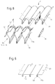
- Fig. 7
- als perspektivische Explosionsdarstellung einen erfindungsgemäßen Balg im unteren Bereich bzw. im Bereich des Übergangs zwischen einer Balgseitenwand und dem Balgboden;
- Fig. 8
- als perspektivische Explosionsdarstellung einen erfindungsgemäßen Balg in einer anderen Ausbildung im Bereich zwischen einem unteren Balgübergangsbogen und dem Balgboden und
- Fig. 9
- eine weitere erfindungsgemäße Balgausbildung.
- Fig. 1
- a bellows formed as a closed tube with two side walls, a roof, a floor and transition bend between the side walls on the one hand and the roof and the floor on the other hand, as is customary and the invention is based on a cross section;
- Fig. 2
- a side view of an articulated vehicle in the area of the mutually facing end faces of the articulated interconnected sub-vehicles, between which a bellows is installed;
- Fig. 3
- in a larger representation the fold contour of the bellows in the area of the roof, the side walls and the transition arch, as is provided in all embodiments of the invention;
- Fig. 4
- in a larger representation the fold or corrugated contour of the bellows in the region of the bellows bottom, as is provided in one embodiment of the invention;
- Fig. 5
- a cross section through an inventive bellows in the lower bellows area;
- Fig. 6
- in a perspective view a bellows base according to the invention;
- Fig. 7
- as a perspective exploded view of a bellows according to the invention in the lower area or in the area of the transition between a bellows side wall and the bellows bottom;
- Fig. 8
- as a perspective exploded view of a bellows according to the invention in a different embodiment in the area between a lower bellows transition bend and the bellows bottom and
- Fig. 9
- a further bellows formation according to the invention.
In üblicher Weise ist gemäß Fig. 1 ein Faltenbalg 1 mit dem Balgdach 2,
zwei Balgseitenwänden 3 und 4 sowie dem Balgboden 5 zwischen
zwei gelenkig miteinander verbundenen Fahrzeugen
beziehungsweise Fahrzeugteilen
6,7 gemäß Fig. 2 angeordnet,
dabei eine Übergangsbrückenkonstruktion 8 und die
Kupplung 9 umschließend. Bei den beiden Fahrzeugteilen handelt
es sich insbesondere um die beiden Glieder eines Gelenkomnibusses,
dessen Innenräume der Fahrzeugglieder nur wenig im
Querschnitt beeinträchtigt sich über einer Drehplattform
fortsetzen, die auf einem Drehkranzgelenk abgestützt ist.
Fußböden der beiden Fahrzeugglieder und der Drehplattform sind
im Übergangsbereich, sowie möglichst bis zum vorderen
und hinteren Fahrzeugende, ohne Stufe in geringer Höhe über
der Fahrbahn angeordnet, es handelt sich also um einen sogenannten
Niederflurgelenkomnibus, wobei Antrieb, Achsanordnung
usw. erfindungsunabhängig sind bzw. der erfindungsgemäße
Faltenbalg unabhängig von der Ausbildung des Gelenkomnibusses
insoweit ist.1 is a bellows 1 with the
Der tunnelförmige Teil des Faltenbalges mit Faltenbalgdach 2
und Seitenwänden 3,4 erstreckt sich als Einheit vom unteren
Ende der einen Seitenwand 3 bzw. 4 über dieses Seitenwand,
einen Übergangsbogen zum Dach, das Dach, einen Übergangsbogen
vom Dach zur anderen Seitenwand 4 bzw. 3 und diese andere
Seitenwand bis zu deren unterem Ende (Fig. 1). In diesem
Bereich sind die vom unteren Ende der einen Seitenwand bis
zum unteren Ende der anderen Seitenwand durchgehend zickzackförmigen
Falten aus Materialbahnen 10 gebildet, wobei
jeweils zwei Materialbahnen, die aufeinanderfolgen durch eine
einen Rahmen
bildende erste äußere Klemmleiste
11 bzw. durch eine einen Rahmen bildende erste innere
Klemmleiste 12 zusammengehalten
sind,
die die äußeren und inneren Balgkanten bilden.
Ein Balgfaltenquerschnitt im Bereich
der Seitenwände 3,4 und des Daches 2 des Faltenbalges ist
in Fig. 3 dargestellt. In den oberen Übergangsbogen 13 und
den unteren Übergangsbogen 14 kann zwischen je zwei Falten,
die vom unteren Ende der einen Seitenwand bis zum unteren
Ende der anderen Seitenwand verlaufen, auf den Bereich der
Übergangsbogen beschränkt, jeweils eine zusätzliche Falte
angeordnet sein, wie es an sich bekannt ist und dazu dient,
die versteifende Wirkung der Übergangsbogen zu mindern und
dazu beizutragen, daß über den Balgumfang eine nahezu gleiche
Nachgiebigkeit herrscht mit dem bereits erwähnten Ziel, Relativbewegungen
zwischen zwei miteinander gelenkig gekuppelten
Fahrzeugen durch den Balg möglichst wenig zu behindern. The tunnel-shaped part of the bellows with
Ein bevorzugter Balgquerschnitt im Bereich des Balgbodens
5 ist in Fig. 4 dargestellt. Zwischen je zwei zweiten
äußeren, als Kantprofilstäbe ausgebildeten Klemmleisten
16,
in Fig. 3 mit 11 bezeichnet,
ist eine Materialbahn 17, in Fig. 3 mit 10 bezeichnet, so angeordnet, daß ein
rinnenförmiger, etwa halbkreisförmiger Querschnitt vorliegt,
bei dem die Wölbung nach dem Inneren des Faltenbalges gerichtet
ist, d.h. die Rinnen nach außen hin offen sind. Insoweit liegt
ebenfalls eine bei Faltenbälgen bekannte Querschnittsform in der
Form eines Wellenbalges
vor, die deshalb nicht näher erläutert werden muß. Ein Balgboden
5 mit einer solchen Querschnittsform ist nun als dem
übrigen, tunnelförmigen Balgteil 2-4, 13,14 als selbständig
an- und ausbaubare Einheit zugeordnet, wie es rein schematisch
in Fig. 5 dargestellt ist. Die unteren Übergangsbogen
14 sind noch Teil des tunnelförmigen Bauteils 2-4, 13,14,
der Balgboden 5 ist zwischen den unteren Übergangsböden 14
eingesetzt und mit lösbaren Befestigungsmitteln 160 gehalten.
Durch Überlappung von unteren Übergangsbögen 14 und Boden 5
ist angedeutet, daß die Verbindung so ausgebildet ist, daß
auch in diesen Bereichen keine Umgebungseinflüsse in das
Balginnere gelangen.A preferred bellows cross section in the area of the
Im einzelnen besteht nun bei einer ersten erfindungsgemäßen
Balgausbildung der Balgboden 5 aus einer Reihe von Stäben 170,
die aus Metall, z.B. einer Aluminiumlegierung oder einem
zweckentsprechenden Kunststoff bestehen können. Der Querschnitt
dieser Stäbe 170 kann oval bzw. elliptisch sein, wie
es in Fig. 6 dargestellt ist, wobei die längere Achse des
Ovals bzw. der Ellipse vertikal steht, um die nötige Steifigkeit
gegen Durchhängen gewährleisten zu können. Der Querschnitt
der Stäbe 170 kann jedoch auch kreisrund sein oder
die Stäbe 170 können geeignete Kantenprofile sein. Im Fall
eines elliptischen oder kreisrunden Querschnitts handelt
es sich vorzugsweise um Hohlprofile. Eine Mehrzahl dieser
Stäbe 170 sind parallel zueinander angeordnet,
wobei die Stäbe 170
in Balg- bzw. Fahrzeuglängsrichtung
aufeinander folgen. Zum Anschluß dieser Stäbe 170
an den unteren Übergangsbogen können die Stäbe 170 an beiden
Enden geschlitzt sein, Endabschnitte 18 gemäß Fig. 7 bilden
und mit diesen geschlitzten Endabschnitten 18 auf je ein
Konsol 19 aufgesteckt sein, das am unteren Ende je einem
der ersten äußeren Klemmleisten 11 fest zugeordnet ist. Jeweilige
Klemmleiste 11 und jeweiliges Konsol 19 können miteinander verschweißt,
verklebt oder in einer anderen geeigneten Weise fest und
dauerhaft miteinander verbunden sein. Dies lösbare Verbindung
zwischen jeweiligem Stabende 18 und jeweiligem Konsol
19 kann durch je einen Splint 20 oder ein anderes geeignetes
Befestigungsmittel erfolgen.In detail, there is now a first invention
Bellows formation of the bellows base 5 from a series of
Im Fall, daß der Balgboden 5 allein von einer geeigneten
Anzahl solcher Stäbe 170 gebildet wird, hat die Gesamtheit
des Balges die notwendige Stabilität und, wenn die Verbindung
zwischen den Stabenden 18 und den Konsolen 19 mittels
der Splinte 20 in zweckgerichteter Weise erfolgt, ist die
Nachgiebigkeit des Balges entsprechend den Anforderungen
aus den Bewegungen der Fahrzeuge relativ zueinander nicht
beeinträchtigt. Gegebenenfalls kann eine räumliche Beweglichkeit
dadurch geschaffen werden, daß die Splinte 20 fest
in den Konsolen 19 gehalten und die Stabenden 18 um die
Längsachsen der Splinte 20 schwenkbar sind, während die
Konsolen 19 so den
ersten äußeren Klemmleisten
11 zugeordnet sind, daß sie um
eine lotrechte Achse schwenkbar sind. Es muß die Wirkung
einer steifen, starr angeschlossenen Platte vermieden sein.In the event that the
Soll nun zusätzlich der Balgboden verhindern, daß auch im
Bodenbereich Umwelteinflüsse in das Balginnere gelangen,
so genügt die mit den Stäben 170 erzielbare Balgstabilität
nicht. Die Stäbe 170 müssen dann als Armierung einem Balgboden
zugeordnet werden, dessen Material dem in den Balgseitenwänden
und dem Balgdach verwendeten Material entspricht,
also insbesondere ein gummiertes Gewebe ist, wobei das Gewebe
in üblicher Weise ein vorzugsweise textiles Gewebe ist und
Gummi für jeden imprägnierenden natürlichen oder künstlichen
Werkstoff steht.Should now additionally prevent the bellows bottom that in
Environmental influences reach the inside of the bellows,
the bellows stability achievable with the
Gemäß Fig. 6 handelt es sich bei einer einfachsten Lösung
bei dem Boden um eine ebene Bahn aus einem flexiblen Faltenbalgstoff
21, auf dessen Unterseite Schlaufen 22 aufgenäht
sind, durch die die Metallarmierung in der Form der Stäbe 170
geschoben ist.6 is a simplest solution
with the floor around a flat sheet of
Der Einbau eines solchen Bodens ergibt sich aus Fig. 7 und es ist ersichtlich, daß es sich trotz der Möglichkeit guter Abdichtung um einen Balgboden extrem geringer Dicke bzw. Höhe handelt.The installation of such a floor is shown in FIGS. 7 and it can be seen that despite the possibility of good Sealing around a bellows base of extremely small thickness or Height.
Zwischen dem gemäß Fig. 6 aus einer Stoffbahn aus flexiblen
Faltenbalgstoff 21 und Metallarmierungen in der Form der Stäbe 170
bestehenden
Balgboden 5 und jeder der Seitenwände 3,4 ist ein unterer
Übergangsbogen 14 als zunächst selbständiges Bauteil vorgesehen
(Fig. 1,5,7). Im jeweiligen Übergangsbogen sind aus je zwei Materialbahnen
23 so viele bogenförmig verlaufende Falten gebildet,
wie es der Faltenzahl in den Seitenwänden entspricht. Jede
Materialbahn 23 weist einen Querschnitt 24 auf, der bis zu
einem Klemmleisten abschnitt 25 reicht, in dem die jeweiligen beiden
Materialbahnen 23 entlang ihren inneren Kanten zusammengehalten
sind. Jeder dieser Klemmleisten abschnitte
25 beginnt am bodennahen Ende der Materialbahnen 23, verläuft
über die Quereinschnitte 24 beider Materialbahnen
hinaus und endet in einem Abstand a vor den seitenwandnahen
Enden der Übergangsbogen 14 der der Faltentiefe in den Seitenwänden
entspricht. Im unteren Bereich sind die beiden
Materialbahnen 23 auf einer Länge durch eine entsprechende dritte
Klemmleiste 26 zusammengehalten, die zwischen dem bodennahen
Ende des Abstandes a beginnt und an den Quereinschnitten
24 endet. Die Materialbahnen 23 bilden insofern Übergangsbogen
als ihre oberen Kanten 27 an den Quereinschnitten
24 etwa horizontal wie der Balgboden verlaufen, um kontinuierlich
in seitenwandzugeordneten Abschnitten zu enden, die
vertikal wie die Seitenwände verlaufen.6 from a web of flexible material
Bellows 21 and metal reinforcements in the form of
Zur Zuordnung des Übergangsbogens
zwischen Faltenbalgboden 5 und jeweiliger Seitenwand 3 bzw.
4 ist der Boden 5 bzw. der flexible Faltenbalgstoff 21 des
Faltenbalgbodens 5
auf der Oberseite des Faltenbalgstoffs 21 mit einem Flauschband
27 als einem Teil eines Klettverschlusses versehen, wie
der Unterseite des Abschnitts 20 am bodenseitigen Ende ein
Klettband 28 als zweitem Teil des Klettverschlusses zugeordnet
ist. Unter- und Oberseite vom Abschnitt 20 bzw. von
flexiblem Faltenbalgstoff 21 ergeben sich, nachdem die Teile
des jeweiligen Abschnitts 20 am unteren Rand der Klemmschienen
25 in eine horizontale Position geklappt sind, wie es
in Fig. 7 dargestellt ist. In dieser Position der Abschnitte
20 werden diese auf die Materialbahn bzw. den flexiblen Faltenbalgstoff
21 aufgelegt, so daß die Teile des Klettbandverschlusses
27,28 aufeinander zu liegen kommen und die
lösbare, feste und dichte Verbindung zwischen Übergangsbogen
14 und Faltenbalgboden 5 in dessen Ausbildung nach
Fig. 6 hergestellt ist, wie es anhand von FIg. 7 nachvollziehbar
ist, insbesondere wenn der obige Beschreibungsteil
zuhilfe genommen wird. To assign the transition sheet
between the
Um nun die Verbindung zur jeweiligen Balgseitenwand 3 bzw.
4 herzustellen, werden die beiden zunächst noch aneinanderliegenden
seitenwandseitigen, freien Endabschnitte der Materialbahnen
23 in die jeweilige Falte der jeweiligen Seitenwand
eingeführt, um das Maß a, das der Faltentiefe entspricht,
bis die seitenwandseitigen Stirnseiten der Klemmleisten abschnitte 25
bzw. der dritten Klemmleisten 26
26 an einer der ersten inneren Klemmleisten 12 der jeweiligen Seitenwand
in Anlage kommen, die freien seitenwandseitigen Abschnitte
des Verbindungsteils außerhalb des Bereichs der Klemmleisten abschnitte
25 bzw. der dritten Klemmleisten 26
26 bzw. im Bereich der Länge a aufgeklappt, bis sie an den
Materialbahnen einer Seitenwandfalte anliegen und fest mit
diesen Materialbahnen verbunden werden, beispielsweise durch
Kleben, Nähen, Vulkanisieren. Im Gegensatz zu der Verbindung
zwischen Verbindungsteil 23 und Boden, die in dem Klettverschluß
27,28 lösbar ist, kann bzw. sollte die Verbindung
zwischen Übergangsteil und jeweiliger Seitenwand unlösbar
sein.In order to connect to the respective bellows
In der beschriebenen Weise sind alle Materialbahnpaare des
Übergangsteils ausgebildet und werden sie in der beschriebenen
Weise mit Seitenwand und Boden verbunden und in wiederum
entsprechender Weise werden zwei Verbindungsteile mit dem
Boden im Bereich der beiden Bodenlängsränder und der jeweiligen
der beiden Seitenwände verbunden. Die Verbindung der
Verbindungsteile mit Boden und jeweiliger Seitenwand erfolgt
nach dem Anschluß der Metallarmierungen 17 an die Konsolen
19 der Seitenwände in der beschriebenen Weise.In the manner described, all pairs of material are
Transitional part trained and they are described in the
Way connected to the side wall and floor and in turn
accordingly, two connecting parts with the
Floor in the area of the two longitudinal floor edges and the respective
of the two side walls connected. The connection of the
Connecting parts with the floor and the respective side wall are made
after connecting the
Bei Ausbildung des Faltenbalgbodens als Wellenbalg gemäß
Fig. 4 erfolgt die Verbindung dieses Bodens mit der jeweiligen
faltenbalgförmigen Seitenwand bzw. deren unterem Übergangsbogen
gemäß Fig. 8, wobei die Seitenwände 3,4 wie in
Fig. 7 dargestellt und beschirieben ausgebildet sind, in
Fig. 8 aber nur das bodenseitige Ende des einen unteren
Übergangsbogens 14 einer Seitenwand dargestellt ist. Der
Übergang vom Faltenprofil der Seitenwand
bzw. des Übergangsbogens 14
zum Wellenprofil
des Bodens erfolgt dadurch, daß die erste innere Klemmleiste 12 der inneren
Faltenkanten nicht an das Faltenende herangeführt, sondern
um das Maß b vor dem Faltenende endet. In den Bereichen
zwischen den Enden der ersten inneren Klemmleisten 12 und dem Faltenende,
also im Bereich des Maßes b, legt sich nun jede Falte in
die Kontur der Welle, sie kann in die Wellen zwischen je
zwei zweiten äußeren Klemmleisten 16 des Bodens 5 eingeführt und dort mit
einem Klettverschluß 27,28 dicht an das Bodenmaterial angelegt
und mit diesem lösbar verbunden werden. Der festeren,
aber ebenfalls lösbaren Verbindung dient eine erste Endausbildung
29 der jeweiligen Klemmleiste 16 der Bodenwellen, eine
entsprechende zweite Endausbildung 11a der ersten äußeren Klemmleisten 11
und ein entsprechendes Verbindungsprofil 30 in Verbindung
mit Schrauben, Nieten o.dgl., die durch übereinstimmende
Löcher der beiden Endausbildungen 29,11a sowie des Verbindungsprofils
30 und des Faltenbalgstoffes von Seitenwand
bzw. Übergangsbogen und Boden hindurchgeführt sind.When the bellows base is designed as a corrugated bellows
Fig. 4 is the connection of this floor with the respective
bellows-shaped side wall or its
Bei dieser Lösung bilden die ersten äußeren Klemmleisten 11 im Dachbereich,
in den Seitenwandbereich und in den Bereichen der Übergangsbogen
einerseits und die zweiten äußeren Klemmleisten 16 andererseits nach
Herstellung der lösbaren Verbindung mittels der Verbindungsprofile
30 übliche ringsumlaufende Zwischenrahmen des Faltenbalges.
Durch die Ausbildung des Bodens 5 als Wellenbalg
ist eine geringere Bodendicke und eine größere Annäherung
an die Fahrbahn möglich, ohne daß der Verschleiß zu erwarten
ist, der dann vorliegt, wenn bei gleicher Bodenfreiheit der
Faltenbalg ringsum, also auch im Bodenbereich zickzackförmige
Falten gemäß Fig. 3 hätte. Trotzdem ist aber einem Verschleiß
des Wellenbalgbodens 5 gemäß Fig. 8 weiter noch dadurch Rechnung
getragen, daß die zweiten äußeren Klemmleisten 16 die Bodenfreiheit definieren,
diese aus abriebfestem Material hergestellt sind bzw.
sein können und so das eigentliche Balgmaterial, also das
beschichtete Gewebe vor Verschleiß bewahrt ist. Sind aber
die zweiten äußeren Klemmleisten 16 tatsächlich verschlissen, so kann der Balgboden
5 in einfacher Weise ausgebaut werden, während Seitenwände,
Dach und Übergangsbogen im Einbauzustand verbleiben,
der ausgebaute Boden kann durch einen Ersatzboden ersetzt
werden, der ausgebaute Boden ist aber seinerseits nicht als
gesamte Baugruppe unbrauchbar geworden; seine Reparatur ist
verhältnismäßig einfach dadurch möglich, daß die schadhaft
gewordenen zweiten äußeren Klemmleisten 16 ausgetauscht werden und die Bodengruppe
für die Wiederverwendung zur Verfügung steht. Die zweiten äußeren
Klemmleisten 16 entsprechen funktionell den Stäben 170 bei der
Lösung gemäß Fig. 7, sie sind "Kantprofile" im Sinne der
Erfindung, die Lösung gemaß Fig. 8 stellt die optimale
Realisierung des Grundgedankens der Erfindung dar.In this solution, the first outer terminal strips 11 form in the roof area,
in the side wall area and in the areas of the transition arch
on the one hand and the second outer terminal strips 16 on the other
Production of the detachable connection by means of the connection profiles
30 usual all-round intermediate frames of the bellows.
By designing the bottom 5 as a bellows
is a smaller bottom thickness and a larger approximation
possible on the road without expecting wear
is, which is present when the
Bellows all around, including zigzag in the
Um weitere, einfache Möglichkeit, einen Balgboden einem
aus Dach, Seitenwänden und Übergangsbogen bestehenden Balghauptkörper
auswechselbar zuzuordnen, ist in Fig. 9 dargestellt.
Zwischen den unteren Übergangsbogen ist ein Tuch 31
angeordnet, das glatt oder wie die Seitenwände gefaltet sein
kann. Es ist in die Falten der unteren Übergangsbogen eingelegt,
so daß eine Überlappung entsteht und dieser Zustand
wird fixiert, indem durch korrespondierende Löcher in den
Falten der Übergangsbogen und in den vorhandenen oder durch
das Einlegen gebildeten Falten des Bodentuches 31 eine Schnur
32 gezogen wird, deren Enden in geeigneter Weise festgelegt
werden.For another easy way to get a bellow bottom
bellows main body consisting of roof, side walls and transition arch
assignable interchangeably is shown in Fig. 9.
There is a
Claims (16)
- A bellows (1) for installation between two pivotably connected vehicles (6, 7) and, in the installed state, forming a peripherally closed tube surrounding a gangway floorplate with a roof (2), side walls (3, 4) and floor (6), characterised in that the tube is in two parts, the upper part (2-4) in the peripheral direction consists of the roof (2) and side walls (3, 4) as a unit and the lower part consists of a sub-assembly which can be independently installed and dismantled and constitutes the floor (5) and is connected by releasable fastening means to the side walls (3, 4) in the region of the lower ends thereof so that after the sub-assembly forming the floor has been associated, the peripherally closed tube is formed, the connection being such that even in these regions no environmental influences can reach the interior of the bellows (1).
- A bellows according to claim 1, the bellows cross-section in the installed state having the shape of an upright rectangle with rounded corners, characterised in that the side walls (3, 4) of the bellows end at the lower ends in transitional curves (14), and the ends thereof remote from the side walls (3, 4) are releasably connected to the bellows floor (5) forming a sub-assembly.
- A bellows according to claim 1 or 2, characterised in that the bellows (1) in the region of the roof (2) and the side walls (3, 4) has the same distance between the inner and outer bellows edges or fold edges (11, 12) and the thickness of the bellows floor (5) is considerably less than the distance between the inner and outer bellows edges (11, 12) in the region of the roof (2) and side walls (3, 4).
- A bellows according to any of claims 1 to 3, characterised in that the bellows floor (5) is in the form of a corrugated bellows (16, 17).
- A bellows according to claim 4, characterised in that the corrugations in the bellows floor (5) formed by the web (17) of material of the bellows (16, 17) are inwardly curved.
- A bellows according to any of claims 2 to 5, characterised in that folds of the bellows extend from the free end of one lower transitional curve (14) over the adjoining side wall (3, 4), the roof (2) and the other side wall (4, 3) continuously to the free end of the other lower transitional curve (14) and an intermediate fold is disposed between each pair of successive aforementioned folds in the region of the lower transitional curves (14).
- A bellows according to claim 3, characterised in that the bellows floor (5) has a number of rods (170), the rods (170) being disposed parallel to one another and the rods (170) following one another in the longitudinal direction of the bellows (1).
- A bellows according to claim 7, characterised in that the rods (170) are axially symmetrical.
- A bellows according to claim 7, characterised in that the cross-sections of the rods (170) form ellipses with their major axes on edge.
- A bellows according to claim 8 or 9, characterised in that the rods (170) are hollow profiles.
- A bellows according to any of claims 7 to 9, characterised in that a cloth (21) is smoothly stretched between the free ends of the lower transitional curve (14) and the rods (170) are passed through loops (22) associated with the cloth.
- A bellows according to claim 11, characterised in that the cloth (21) is uniform with the material of the bellows roof (2), the bellows side walls (3, 4) and the transitional curve (13, 14) and is a rubber-coated fabric but is intrinsically elastic.
- A bellows according to claims 4 and 5, characterised in that edge profile rods (16) hold together individual webs of the bellows (5) which are curved upwards with an approximately semicircular cross-section between each pair of edge profile rods (16).
- A bellows according to claim 13, comprising edge profile rods (16) which extend from the free end of a lower transitional curve (14) to the free end of the other lower transitional curve (14) and hold together webs of bellows forming turn-over edges, characterised in that the edge profile rods (16) of the bellows floor (5) are releasably connected to second end formations (11a) on the first outer clamping strips of the roof (2) and side walls (3, 4).
- A bellows according to claim 14, characterised in that the bellows webs of the bellows side walls (3, 4) or their lower transitional curves (14) extend away over the second end formations (11a) in the region of the lower transitional curves (14) and abut the underside of the webs (17) of material of the bellows floor (5) and are tightly but releasably connected thereto.
- A bellows according to claim 15, characterised in that the tight but releasable connection is made by a Velcro fastener.
Applications Claiming Priority (4)
| Application Number | Priority Date | Filing Date | Title |
|---|---|---|---|
| DE19934322098 DE4322098A1 (en) | 1993-07-02 | 1993-07-02 | Intercommunicating device, in particular for articulated road vehicles |
| DE4322098 | 1993-07-02 | ||
| DE4341231 | 1993-12-03 | ||
| DE4341231A DE4341231A1 (en) | 1993-07-02 | 1993-12-03 | Bellows for installation as a transition protection between two articulated vehicles |
Publications (2)
| Publication Number | Publication Date |
|---|---|
| EP0631890A1 EP0631890A1 (en) | 1995-01-04 |
| EP0631890B1 true EP0631890B1 (en) | 1998-04-08 |
Family
ID=25927339
Family Applications (1)
| Application Number | Title | Priority Date | Filing Date |
|---|---|---|---|
| EP94110306A Expired - Lifetime EP0631890B1 (en) | 1993-07-02 | 1994-07-02 | Concertina wall to be mounted between articulated road vehicles |
Country Status (5)
| Country | Link |
|---|---|
| EP (1) | EP0631890B1 (en) |
| AT (1) | ATE164808T1 (en) |
| DE (2) | DE4341231A1 (en) |
| DK (1) | DK0631890T3 (en) |
| ES (1) | ES2115813T3 (en) |
Cited By (5)
| Publication number | Priority date | Publication date | Assignee | Title |
|---|---|---|---|---|
| DE10044303C1 (en) * | 2000-09-07 | 2001-10-31 | Contitech Elastomer Besch Gmbh | Passage bellows unit for articulated vehicle has floor rods not connected to its side wall strips |
| DE10154033B4 (en) * | 2000-11-25 | 2006-10-19 | Hübner GmbH | Bellows a transition between two articulated vehicles |
| EP1810852A1 (en) * | 2006-01-19 | 2007-07-25 | HÜBNER GmbH | Bellows of a passage between two articulated vehicles |
| EP2796306A1 (en) | 2013-04-25 | 2014-10-29 | Hübner GmbH & Co. KG | Connection between two pivotally connected vehicles |
| DE202013012585U1 (en) | 2013-04-25 | 2017-08-13 | HÜBNER GmbH & Co. KG | Transition between two articulated vehicles |
Families Citing this family (12)
| Publication number | Priority date | Publication date | Assignee | Title |
|---|---|---|---|---|
| DE19721285A1 (en) * | 1997-05-21 | 1998-11-26 | Gebr Hennig Gmbh | Intercommunication gangway between articulated vehicles |
| DE10023701A1 (en) * | 2000-05-09 | 2001-11-22 | Contitech Elastomer Besch Gmbh | Bellows-type passage for articulated vehicle; has folds or corrugations, with folds of base formed as transverse flexible corrugations or folds and elastic clamp element, from which base is suspended |
| US6840529B2 (en) | 2002-10-17 | 2005-01-11 | David B. Call | Articulated pickup truck camper/trailer |
| ITBO20050031U1 (en) * | 2005-05-31 | 2006-12-01 | P E I Protezione Elaborazionei | CONNECTION ELEMENT FOR IRRIGIDATION PROFILES OF A BELLOWS |
| DE102005039472B4 (en) * | 2005-08-20 | 2016-06-09 | Hübner GmbH | Passenger stairs or passenger boarding seal |
| EP1995086B1 (en) * | 2007-05-25 | 2011-10-19 | HEMSCHEIDT FAHRWERKTECHNIK GmbH & Co. KG | Bellows assembly for articulated vehicles and related floor |
| IT1390798B1 (en) * | 2008-07-31 | 2011-10-19 | Pei Protezioni Elaborazioni | CONNECTION DEVICE BETWEEN THE BELLOWS AND THE FRAME OF ARTICULATED VEHICLES. |
| PL2604451T3 (en) * | 2011-12-16 | 2014-09-30 | Huebner Gmbh & Co Kg | Gaiter or gangway bellows for the intersection of two vehicles with a jointed connection |
| EP2853462B1 (en) * | 2013-09-26 | 2019-02-27 | Hübner GmbH & Co. KG | Bellows for a transition between two articulated vehicles or vehicle parts or bellows of a canopy of an air passenger boarding bridge or steps |
| EP2998135B1 (en) | 2014-09-19 | 2017-12-13 | Dellner Couplers AB | Gangway for connecting a first car with a second car |
| PL3075579T3 (en) * | 2015-04-02 | 2020-11-16 | HÜBNER GmbH & Co. KG | Bellows, e.g. the transition between two vehicles with a jointed connection |
| ES2899625T3 (en) * | 2019-05-22 | 2022-03-14 | Ultimate Europe Transp Equipment Gmbh | bellows element |
Family Cites Families (4)
| Publication number | Priority date | Publication date | Assignee | Title |
|---|---|---|---|---|
| US2193156A (en) * | 1939-03-17 | 1940-03-12 | Vernon F Antoine | Articulated vehicle construction |
| DE3612425A1 (en) * | 1986-04-12 | 1987-10-15 | Huebner Gummi & Kunststoff | Intercommunicating gangway protection |
| DE3634641A1 (en) * | 1986-10-10 | 1988-04-14 | Huebner Gummi & Kunststoff | BELLOWS |
| ES2113911T3 (en) * | 1991-11-27 | 1998-05-16 | Huebner Gummi & Kunststoff | BELLOWS FOR ARTICULATED VEHICLES. |
-
1993
- 1993-12-03 DE DE4341231A patent/DE4341231A1/en not_active Ceased
-
1994
- 1994-07-02 DK DK94110306T patent/DK0631890T3/en active
- 1994-07-02 AT AT94110306T patent/ATE164808T1/en active
- 1994-07-02 DE DE59405614T patent/DE59405614D1/en not_active Expired - Lifetime
- 1994-07-02 EP EP94110306A patent/EP0631890B1/en not_active Expired - Lifetime
- 1994-07-02 ES ES94110306T patent/ES2115813T3/en not_active Expired - Lifetime
Cited By (8)
| Publication number | Priority date | Publication date | Assignee | Title |
|---|---|---|---|---|
| DE10044303C1 (en) * | 2000-09-07 | 2001-10-31 | Contitech Elastomer Besch Gmbh | Passage bellows unit for articulated vehicle has floor rods not connected to its side wall strips |
| DE10154033B4 (en) * | 2000-11-25 | 2006-10-19 | Hübner GmbH | Bellows a transition between two articulated vehicles |
| EP1810852A1 (en) * | 2006-01-19 | 2007-07-25 | HÜBNER GmbH | Bellows of a passage between two articulated vehicles |
| DE102006002655A1 (en) * | 2006-01-19 | 2007-08-09 | Hübner GmbH | Bellows a transition between two articulated vehicles |
| DE102006002655B4 (en) * | 2006-01-19 | 2008-03-06 | Hübner GmbH | Bellows a transition between two articulated vehicles |
| US7568435B2 (en) | 2006-01-19 | 2009-08-04 | Hübner GmbH | Bellows of a connection between two hinge-linked vehicles |
| EP2796306A1 (en) | 2013-04-25 | 2014-10-29 | Hübner GmbH & Co. KG | Connection between two pivotally connected vehicles |
| DE202013012585U1 (en) | 2013-04-25 | 2017-08-13 | HÜBNER GmbH & Co. KG | Transition between two articulated vehicles |
Also Published As
| Publication number | Publication date |
|---|---|
| DE59405614D1 (en) | 1998-05-14 |
| ATE164808T1 (en) | 1998-04-15 |
| EP0631890A1 (en) | 1995-01-04 |
| ES2115813T3 (en) | 1998-07-01 |
| DE4341231A1 (en) | 1995-06-08 |
| DK0631890T3 (en) | 1999-01-04 |
Similar Documents
| Publication | Publication Date | Title |
|---|---|---|
| EP0631890B1 (en) | Concertina wall to be mounted between articulated road vehicles | |
| DE2404966C3 (en) | Endless track mat for a vehicle with swiveling track | |
| DE502006000181C5 (en) | Sputugenabdeckung for articulated vehicles | |
| DE3928379C2 (en) | ||
| EP1391329B1 (en) | Fold or corrugation of a bellows or passageway between two artculated vehicles or vehicle parts | |
| EP2033827A2 (en) | Collapsible roof fitting for a motor vehicle | |
| CH621303A5 (en) | ||
| DE19821083B4 (en) | Bellows of a transition between two articulated vehicles or vehicle parts | |
| DE4322098A1 (en) | Intercommunicating device, in particular for articulated road vehicles | |
| EP0653319B1 (en) | Bellows as protection of the passage between articulated vehicles | |
| EP0275365B1 (en) | Bellows for a communication passage for vehicles | |
| DE202018103500U1 (en) | Connecting member or belt tensioner for a hood on a vehicle for carrying loads and soft top | |
| DE3613729A1 (en) | Communication passage protection in the form of a bellows | |
| DE4407805C2 (en) | Car body for rail vehicles | |
| DE10005994C1 (en) | Track joint covering system for articulated vehicle has folding bellows and bellows skirt cooperating with folding bellows and articulation coupling at opposite ends | |
| DE102004005589B4 (en) | Awning roof for a vehicle, in particular for a champing vehicle | |
| DE19721285A1 (en) | Intercommunication gangway between articulated vehicles | |
| EP0252221B1 (en) | Protection device for intercommunication passage between vehicles | |
| DE102022110440B3 (en) | Openable side tarpaulin wall system and sliding stanchions | |
| EP3210802B1 (en) | Connection between two vehicles with jointed couplings | |
| DE102009052152A1 (en) | Engine bonnet for motor vehicle, has two reinforcement pieces arranged in cavity and connected with outer covering part and inner part, respectively, where two brackets of one of reinforcement pieces are connected with outer covering part | |
| DE19832858A1 (en) | Bellows or elements of a bellows of a transition between two articulated vehicles | |
| DE202022102312U1 (en) | Openable side curtain wall system | |
| EP3081406A1 (en) | Folding bellows for the transition between two vehicles with a jointed connection | |
| EP0882612A1 (en) | Foldable tarpaulin for vehicle bodies and container |
Legal Events
| Date | Code | Title | Description |
|---|---|---|---|
| PUAI | Public reference made under article 153(3) epc to a published international application that has entered the european phase |
Free format text: ORIGINAL CODE: 0009012 |
|
| AK | Designated contracting states |
Kind code of ref document: A1 Designated state(s): AT BE CH DE DK ES FR GB GR IE IT LI LU MC NL PT SE |
|
| RBV | Designated contracting states (corrected) |
Designated state(s): AT BE CH DE DK ES FR GB GR IE IT LI NL PT SE |
|
| 17P | Request for examination filed |
Effective date: 19950616 |
|
| 17Q | First examination report despatched |
Effective date: 19960910 |
|
| GRAG | Despatch of communication of intention to grant |
Free format text: ORIGINAL CODE: EPIDOS AGRA |
|
| GRAG | Despatch of communication of intention to grant |
Free format text: ORIGINAL CODE: EPIDOS AGRA |
|
| GRAH | Despatch of communication of intention to grant a patent |
Free format text: ORIGINAL CODE: EPIDOS IGRA |
|
| GRAH | Despatch of communication of intention to grant a patent |
Free format text: ORIGINAL CODE: EPIDOS IGRA |
|
| GRAA | (expected) grant |
Free format text: ORIGINAL CODE: 0009210 |
|
| AK | Designated contracting states |
Kind code of ref document: B1 Designated state(s): AT BE CH DE DK ES FR GB GR IE IT LI NL PT SE |
|
| REF | Corresponds to: |
Ref document number: 164808 Country of ref document: AT Date of ref document: 19980415 Kind code of ref document: T |
|
| REG | Reference to a national code |
Ref country code: CH Ref legal event code: NV Representative=s name: DIPL.-ING. ETH H. R. WERFFELI PATENTANWALT Ref country code: CH Ref legal event code: EP |
|
| REF | Corresponds to: |
Ref document number: 59405614 Country of ref document: DE Date of ref document: 19980514 |
|
| GBT | Gb: translation of ep patent filed (gb section 77(6)(a)/1977) |
Effective date: 19980505 |
|
| ET | Fr: translation filed | ||
| REG | Reference to a national code |
Ref country code: ES Ref legal event code: FG2A Ref document number: 2115813 Country of ref document: ES Kind code of ref document: T3 |
|
| ITF | It: translation for a ep patent filed |
Owner name: SOCIETA' ITALIANA BREVETTI S.P.A. |
|
| REG | Reference to a national code |
Ref country code: IE Ref legal event code: FG4D Free format text: 79701 |
|
| REG | Reference to a national code |
Ref country code: PT Ref legal event code: SC4A Free format text: AVAILABILITY OF NATIONAL TRANSLATION Effective date: 19980605 |
|
| REG | Reference to a national code |
Ref country code: DK Ref legal event code: T3 |
|
| PLBE | No opposition filed within time limit |
Free format text: ORIGINAL CODE: 0009261 |
|
| STAA | Information on the status of an ep patent application or granted ep patent |
Free format text: STATUS: NO OPPOSITION FILED WITHIN TIME LIMIT |
|
| 26N | No opposition filed | ||
| REG | Reference to a national code |
Ref country code: GB Ref legal event code: IF02 |
|
| PGFP | Annual fee paid to national office [announced via postgrant information from national office to epo] |
Ref country code: CH Payment date: 20110725 Year of fee payment: 18 Ref country code: IE Payment date: 20110721 Year of fee payment: 18 Ref country code: DK Payment date: 20110720 Year of fee payment: 18 |
|
| PGFP | Annual fee paid to national office [announced via postgrant information from national office to epo] |
Ref country code: GB Payment date: 20110721 Year of fee payment: 18 Ref country code: SE Payment date: 20110722 Year of fee payment: 18 Ref country code: GR Payment date: 20110727 Year of fee payment: 18 |
|
| PGFP | Annual fee paid to national office [announced via postgrant information from national office to epo] |
Ref country code: NL Payment date: 20110726 Year of fee payment: 18 Ref country code: BE Payment date: 20110713 Year of fee payment: 18 |
|
| PGFP | Annual fee paid to national office [announced via postgrant information from national office to epo] |
Ref country code: DE Payment date: 20120711 Year of fee payment: 19 Ref country code: IT Payment date: 20120731 Year of fee payment: 19 Ref country code: ES Payment date: 20120726 Year of fee payment: 19 Ref country code: FR Payment date: 20120806 Year of fee payment: 19 |
|
| BERE | Be: lapsed |
Owner name: *HUBNER GUMMI- UND KUNSTSTOFF G.M.B.H. Effective date: 20120731 |
|
| PGFP | Annual fee paid to national office [announced via postgrant information from national office to epo] |
Ref country code: PT Payment date: 20120102 Year of fee payment: 19 |
|
| REG | Reference to a national code |
Ref country code: NL Ref legal event code: V1 Effective date: 20130201 |
|
| REG | Reference to a national code |
Ref country code: GR Ref legal event code: ML Ref document number: 980401373 Country of ref document: GR Effective date: 20130104 |
|
| REG | Reference to a national code |
Ref country code: SE Ref legal event code: EUG |
|
| GBPC | Gb: european patent ceased through non-payment of renewal fee |
Effective date: 20120702 |
|
| PGFP | Annual fee paid to national office [announced via postgrant information from national office to epo] |
Ref country code: AT Payment date: 20120711 Year of fee payment: 19 |
|
| REG | Reference to a national code |
Ref country code: DK Ref legal event code: EBP |
|
| PG25 | Lapsed in a contracting state [announced via postgrant information from national office to epo] |
Ref country code: GB Free format text: LAPSE BECAUSE OF NON-PAYMENT OF DUE FEES Effective date: 20120702 Ref country code: NL Free format text: LAPSE BECAUSE OF NON-PAYMENT OF DUE FEES Effective date: 20130201 Ref country code: SE Free format text: LAPSE BECAUSE OF NON-PAYMENT OF DUE FEES Effective date: 20120703 |
|
| REG | Reference to a national code |
Ref country code: IE Ref legal event code: MM4A |
|
| PG25 | Lapsed in a contracting state [announced via postgrant information from national office to epo] |
Ref country code: BE Free format text: LAPSE BECAUSE OF NON-PAYMENT OF DUE FEES Effective date: 20120731 Ref country code: GR Free format text: LAPSE BECAUSE OF NON-PAYMENT OF DUE FEES Effective date: 20130204 |
|
| PG25 | Lapsed in a contracting state [announced via postgrant information from national office to epo] |
Ref country code: IE Free format text: LAPSE BECAUSE OF NON-PAYMENT OF DUE FEES Effective date: 20120702 Ref country code: DK Free format text: LAPSE BECAUSE OF NON-PAYMENT OF DUE FEES Effective date: 20120731 |
|
| REG | Reference to a national code |
Ref country code: PT Ref legal event code: MM4A Free format text: LAPSE DUE TO NON-PAYMENT OF FEES Effective date: 20140102 |
|
| REG | Reference to a national code |
Ref country code: CH Ref legal event code: PL |
|
| REG | Reference to a national code |
Ref country code: AT Ref legal event code: MM01 Ref document number: 164808 Country of ref document: AT Kind code of ref document: T Effective date: 20130702 |
|
| REG | Reference to a national code |
Ref country code: FR Ref legal event code: ST Effective date: 20140331 |
|
| PG25 | Lapsed in a contracting state [announced via postgrant information from national office to epo] |
Ref country code: CH Free format text: LAPSE BECAUSE OF NON-PAYMENT OF DUE FEES Effective date: 20130731 Ref country code: LI Free format text: LAPSE BECAUSE OF NON-PAYMENT OF DUE FEES Effective date: 20130731 Ref country code: DE Free format text: LAPSE BECAUSE OF NON-PAYMENT OF DUE FEES Effective date: 20140201 |
|
| REG | Reference to a national code |
Ref country code: DE Ref legal event code: R119 Ref document number: 59405614 Country of ref document: DE Effective date: 20140201 |
|
| PG25 | Lapsed in a contracting state [announced via postgrant information from national office to epo] |
Ref country code: FR Free format text: LAPSE BECAUSE OF NON-PAYMENT OF DUE FEES Effective date: 20130731 Ref country code: IT Free format text: LAPSE BECAUSE OF NON-PAYMENT OF DUE FEES Effective date: 20130702 Ref country code: AT Free format text: LAPSE BECAUSE OF NON-PAYMENT OF DUE FEES Effective date: 20130702 |
|
| PG25 | Lapsed in a contracting state [announced via postgrant information from national office to epo] |
Ref country code: PT Free format text: LAPSE BECAUSE OF NON-PAYMENT OF DUE FEES Effective date: 20140102 |
|
| REG | Reference to a national code |
Ref country code: PT Ref legal event code: MM4A Free format text: MAXIMUM VALIDITY LIMIT REACHED Effective date: 20140702 |
|
| REG | Reference to a national code |
Ref country code: ES Ref legal event code: FD2A Effective date: 20140908 |
|
| PG25 | Lapsed in a contracting state [announced via postgrant information from national office to epo] |
Ref country code: ES Free format text: LAPSE BECAUSE OF NON-PAYMENT OF DUE FEES Effective date: 20130703 |
|
| PG25 | Lapsed in a contracting state [announced via postgrant information from national office to epo] |
Ref country code: PT Free format text: LAPSE BECAUSE OF EXPIRATION OF PROTECTION Effective date: 20140710 |
|
| PG25 | Lapsed in a contracting state [announced via postgrant information from national office to epo] |
Ref country code: PT Free format text: LAPSE BECAUSE OF EXPIRATION OF PROTECTION Effective date: 20140109 |