EP0631272A2 - Ultraschallwandler - Google Patents
Ultraschallwandler Download PDFInfo
- Publication number
- EP0631272A2 EP0631272A2 EP94302836A EP94302836A EP0631272A2 EP 0631272 A2 EP0631272 A2 EP 0631272A2 EP 94302836 A EP94302836 A EP 94302836A EP 94302836 A EP94302836 A EP 94302836A EP 0631272 A2 EP0631272 A2 EP 0631272A2
- Authority
- EP
- European Patent Office
- Prior art keywords
- acoustic matching
- piezoelectric element
- matching layer
- thickness
- ultrasonic transducer
- Prior art date
- Legal status (The legal status is an assumption and is not a legal conclusion. Google has not performed a legal analysis and makes no representation as to the accuracy of the status listed.)
- Granted
Links
- 238000001514 detection method Methods 0.000 abstract description 5
- 239000000919 ceramic Substances 0.000 description 8
- 230000035945 sensitivity Effects 0.000 description 8
- 239000000463 material Substances 0.000 description 7
- 229920002379 silicone rubber Polymers 0.000 description 5
- 239000002131 composite material Substances 0.000 description 4
- 239000004945 silicone rubber Substances 0.000 description 4
- 230000006866 deterioration Effects 0.000 description 3
- 230000000694 effects Effects 0.000 description 3
- 239000002033 PVDF binder Substances 0.000 description 2
- 229910003781 PbTiO3 Inorganic materials 0.000 description 2
- 239000003822 epoxy resin Substances 0.000 description 2
- 230000002093 peripheral effect Effects 0.000 description 2
- 229920000647 polyepoxide Polymers 0.000 description 2
- 229920000642 polymer Polymers 0.000 description 2
- 229920002981 polyvinylidene fluoride Polymers 0.000 description 2
- 238000006243 chemical reaction Methods 0.000 description 1
- 238000013016 damping Methods 0.000 description 1
- 239000000945 filler Substances 0.000 description 1
- 238000005259 measurement Methods 0.000 description 1
- 230000002040 relaxant effect Effects 0.000 description 1
- 239000000523 sample Substances 0.000 description 1
Images

Classifications
-
- B—PERFORMING OPERATIONS; TRANSPORTING
- B06—GENERATING OR TRANSMITTING MECHANICAL VIBRATIONS IN GENERAL
- B06B—METHODS OR APPARATUS FOR GENERATING OR TRANSMITTING MECHANICAL VIBRATIONS OF INFRASONIC, SONIC, OR ULTRASONIC FREQUENCY, e.g. FOR PERFORMING MECHANICAL WORK IN GENERAL
- B06B1/00—Methods or apparatus for generating mechanical vibrations of infrasonic, sonic, or ultrasonic frequency
- B06B1/02—Methods or apparatus for generating mechanical vibrations of infrasonic, sonic, or ultrasonic frequency making use of electrical energy
- B06B1/06—Methods or apparatus for generating mechanical vibrations of infrasonic, sonic, or ultrasonic frequency making use of electrical energy operating with piezoelectric effect or with electrostriction
- B06B1/0644—Methods or apparatus for generating mechanical vibrations of infrasonic, sonic, or ultrasonic frequency making use of electrical energy operating with piezoelectric effect or with electrostriction using a single piezoelectric element
- B06B1/0662—Methods or apparatus for generating mechanical vibrations of infrasonic, sonic, or ultrasonic frequency making use of electrical energy operating with piezoelectric effect or with electrostriction using a single piezoelectric element with an electrode on the sensitive surface
- B06B1/067—Methods or apparatus for generating mechanical vibrations of infrasonic, sonic, or ultrasonic frequency making use of electrical energy operating with piezoelectric effect or with electrostriction using a single piezoelectric element with an electrode on the sensitive surface which is used as, or combined with, an impedance matching layer
-
- G—PHYSICS
- G10—MUSICAL INSTRUMENTS; ACOUSTICS
- G10K—SOUND-PRODUCING DEVICES; METHODS OR DEVICES FOR PROTECTING AGAINST, OR FOR DAMPING, NOISE OR OTHER ACOUSTIC WAVES IN GENERAL; ACOUSTICS NOT OTHERWISE PROVIDED FOR
- G10K11/00—Methods or devices for transmitting, conducting or directing sound in general; Methods or devices for protecting against, or for damping, noise or other acoustic waves in general
- G10K11/18—Methods or devices for transmitting, conducting or directing sound
- G10K11/26—Sound-focusing or directing, e.g. scanning
- G10K11/32—Sound-focusing or directing, e.g. scanning characterised by the shape of the source
Definitions
- the present invention relates to an ultrasonic transducer which is used in a ultrasonic diagnosing apparatus, for transmitting and receiving ultrasonic waves.
- Fig. 5 shows a conventional ultrasonic transducer of this kind, which comprises a piezoelectric element 11 having a uniform thickness, at least two of ultrasonic matching layers 12, 13 provided on the ultrasonic wave transmitting and receiving side (front surface side) of the piezoelectric element 11 and having a uniform quarter wave length thickness, for relaxing reflection caused by mismatching in acoustic impedance between the piezoelectric element and an object to be detected, so as to effectively radiate ultrasonic waves, a backing member 14 provided at the rear surface of the piezoelectric element 11 so as to have damping and holding functions, and an acoustic lens 15 provided at the front surface of the acoustic matching layer 13 and made of silicone rubber materials, for converging an ultrasonic beam.
- a conventional ultrasonic transducer of this kind which comprises a piezoelectric element 11 having a uniform thickness, at least two of ultrasonic matching layers 12, 13 provided on the ultrasonic wave transmitting and receiving side (front surface side) of the piezo
- the above-mentioned arrangement can have a frequency characteristic having a wide band, and further, can materialize a high resolution since the ultrasonic wave is converged thinly.
- the conventional ultrasonic transducer having the above-mentioned arrangement has offered problems such that ultrasonic signals transmitted to or received from an object to be detected dampen so as to remarkably deteriorate its frequency characteristic in a high frequency range since the attenuation coefficient of the acoustic lens 15 made of silicone rubber materials or the like is high, and such that the sensitivity (efficiency) is remarkably deteriorated due to the attenuation through the acoustic lens 15.
- the present invention is devised in order to solve the above-mentioned problems inherent to the conventional arrangement, and accordingly, one object of the present invention is to provide an ultrasonic transducer which can exhibit a frequency characteristic having a wide band without being affected by attenuation caused by the acoustic lens, and which can enhance the sensitivity (efficiency) so as to obtain an ultrasonic image having a high resolution and a deep detection depth.
- an ultrasonic transducer comprising a piezoelectric element having a uniform thickness and having a concave surface with an arbitrary curvature on the side where ultrasonic waves are transmitted to and received from an object to be detected, and at least one of acoustic matching layers laid on the concave surface of the piezoelectric element, at least one thereof having a ununiform thickness while the acoustic matching layers have a maximum thickness of about one-quarter wave length.
- two acoustic matching layers are provided in the above-mentioned ultrasonic transducer, that is, the first acoustic matching layer laid on a side near the piezoelectric element, has an ununiform thickness with a maximum thickness of about one-quarter wave length, and the second layer laid on the object side has a substantially uniform thickness of about quarter wave length.
- At least one of the acoustic matching layers can have an ununiform thickness and can be curved in directions in which ultrasonic waves are transmitted to and received from an object to be detected, with a maximum thickness of about quarter wave length.
- the matching layer can be concave on the side where ultrasonic waves are transmitted to and received from an object to be detected, and the curved surface of the acoustic matching layer on the side remote from the piezoelectric element can have a curvature which is larger than the curvature of the piezoelectric element.
- a gaussian shape frequency characteristic over a wide band can be obtained, and further, an ultrasonic beam can be converged without using an acoustic lens, at an arbitrary distance due to the curvature of the piezoelectric element, thereby it is possible to enhance the sensitivity of the ultrasonic transducer.
- a pulse-like response wave having a remarkably short wavelength can be obtained, and further, problems of deterioration in the frequency characteristic and the sensitivity (efficiency) can be eliminated, which are caused by the attenuation by an acoustic lens.
- an ultrasonic transducer in a first embodiment of the present invention comprises a concave piezoelectric element 1 having an uniform thickness and having an arbitrary curvature in directions in which ultrasonic waves are transmitted to and are received from an object 5 to be detected, a backing member 2 laid on one of opposite surfaces of the piezoelectric elements on the side remote from the object to be detected, a first acoustic matching layer 3 laid on the other one of the opposite surfaces of the piezoelectric element, which is a concave surface on the side where ultrasonic waves are transmitted to or received from the object to be detected, and having a flat front surface, a second acoustic matching layer 4 laid on the first acoustic matching layer 3, and lead wires 6 (refer to Fig. 3) laid at side surfaces of the backing member 2 and led from the piezoelectric element 1.
- the first acoustic matching layer 3 is formed in the concave surface of the piezoelectric surface 1 so that the thickness thereof is ununiform, having a thickest center part from which the thickness becomes smaller and smaller toward the peripheral part thereof, and accordingly, having a thinnest outermost part.
- the second acoustic matching layer 4 has a substantially uniform thickness in its entirety, different from the first acoustic matching layer, so as to have a contact surface which is adapted to make contact with the object 5 to be detected, and which is substantially flat.
- the piezoelectric element 1 is made of piezoelectric ceramic of a PZT group, PbTiO3 group or the like, and for example, in the case of detection of a human body as the object 5 to be detected, the first and second acoustic matching layers 3, 4 are made of materials having an acoustic impedance of 7 to 15 MRayl, and an acoustic impedance of about 3 Mrayl, respectively. In this embodiment, materials having these impedances are used.
- the concave piezoelectric element 1 of the PbTiO3 group having a thickness with which the frequency was set to 5.0 MHz, the first acoustic matching layer 3 made of a material having an acoustic impedance of 12 MRayl and prepared by adding a filler into epoxy resin, and the second acoustic matching layer 4 made of epoxy resin having an acoustic impedance of 2.8 MRayl were used.
- the thickness of the thickest part (center part), that is, the maximum thickness of the first acoustic matching layer 3 was changed while the thickness of the second acoustic matching layer 4 was fixed to a uniform thickness of about quarter wave length so as to prepare a plurality of ultrasonic transducers.
- a, b, c are the frequency characteristics which were obtained from the first acoustic matching layers 3 having thickness of one-sixth, quarter and two-fifth wave length, respectively.
- the thickness of the first acoustic matching layer 3 be smaller than one-sixth wave length which gives the characteristic a, the frequency characteristic would deteriorate, and should it be larger than the thickness which gives the characteristic c, the frequency characteristic would deteriorate, similar to the characteristic a. From this fact, it has been found that a normal distribution type frequency characteristic over a wide band can be obtained if the thickness of the maximum thickness part of the first acoustic matching layer 3 which has an ununiform thickness is set to about quarter wave length.
- the distance resolution in a direction in which ultrasonic waves are transmitted or received is a capability of how two distal points can be resolved and displayed during transmitting and receiving of pulse waves, that is, the shorter the pulse width, the higher the resolution.
- there are two ways one of which uses a high frequency and the one of which uses a single peak characteristic (gaussian shape characteristic) having a wide band. Should the frequency characteristic be enhanced with a fixed frequency, the latter way, that is, the way having a normal distribution type frequency characteristic having a wide band should be used.
- the characteristic having a distance resolution which is most satisfactory can be obtained by the acoustic matching layer having a thickness of quarter wave length, as given by the frequency characteristic b. Further, it is desirable that the second acoustic matching layer 4 has a thickness of about quarter wave length.
- this embodiment uses the concave piezoelectric element 1 having an arbitrary curvature, an ultrasonic beam having a focus point at an arbitrary position can be formed even though an acoustic lens made of silicone rubber or the like as is a conventional one, is laid on an acoustic matching layer. Accordingly, it is of course possible to prevent deterioration of the frequency characteristic due to attenuation through an acoustic lens made of silicon rubber as is in the conventional one, and further, it is possible to enhance the sensitivity (efficiency).
- this embodiment in comparison in received voltage, that is, sensitivities (efficiency) between an arrangement completely identical with the conventional example and this embodiment in the term of frequency, aperture and focal distance, this embodiment exhibited a frequency characteristic which is higher than the conventional one by about 6 dB.
- the piezoelectric element 1 is made of piezoelectric ceramic, a composite piezoelectric element made of a composite of piezoelectric ceramic and a polymer, or a PVDF piezoelectric element can be used for obtaining a gaussian shape frequency characteristic.
- the acoustic impedance of the piezoelectric element 1 becomes lower than that made of piezoelectric ceramic, the acoustic impedances of the first and second acoustic matching layers 3, 4 have to be, of course, small.
- an ultrasonic transducer in which one acoustic matching layer or more than three acoustic matching layers are used can also exhibit a normal distribution type frequency characteristic over a wide band.
- the second acoustic matching layer 4 has an uniform thickness and has a flat surface adapted to make contact with the object 5 to be detected
- such an arrangement that the second acoustic matching layer 4 has a thickness which is ununiform, similar to the first acoustic matching layer 3, a maximum thickness part thereof having a thickness of about one-quarter of the wavelength, and the surface of the second acoustic matching layer 4 making contact with the object 5 to be detected, is concave, can also exhibit a gaussian shape frequency characteristic over a wide band.
- the single piezoelectric element 1 is used in the ultrasonic transducer in the this embodiment, the so-called array type ultrasonic transducer in which the piezoelectric element 1 is divided into several strips can also exhibit the same effects.
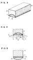
- Fig. 4 is a schematic sectional view illustrating an ultrasonic transducer in the second embodiment of the present invention.
- the ultrasonic transducer is composed of a piezoelectric element 1, a backing member 2, a first acoustic matching layer 3, and a second acoustic matching layer 4.
- the radius R of curvature of the piezoelectric element 1 is determined in view of a focal point to which an ultrasonic beam is focused, and further, the aperture width A of the piezoelectric element 1 is determined, depending upon a frequency and a degree of conversion of an ultrasonic beam. Accordingly, the first acoustic matching layer 3 having a flat front surface cannot be formed on the concave surface part of the piezoelectric element 1 in a certain case, in comparison with the first embodiment in which it can be formed. That is, the height of a deepest part of the concave surface part of the piezoelectric element 1, that is equal to the maximum thickness of the first acoustic matching layer 3, cannot be set to quarter wave length. However, this problem can be solved by the arrangement shown in Fig. 4 in this embodiment.
- the ultrasonic wave transmitting and receiving surface of the concave piezoelectric element 1 having an arbitrary curvature radius R p is covered thereover with the first acoustic matching layer 3, excepting the outer peripheral part of thereof, and further the first acoustic matching layer 3 has a concave surface shape, having a curvature radius R1 so that the maximum thickness part thereof has a thickness of about quarter wave length.
- the second acoustic matching layer 4 is laid on the first acoustic matching layer 3 and has a concave surface shape having a radius of curvature R2 so that the maximum thickness part thereof has a thickness of quarter wave length, similar to the first acoustic matching layer.
- the piezoelectric element 1 is made of piezoelectric ceramic having a frequency of 5.0 MHz
- the first and second acoustic matching layers 3, 4 are made of materials having acoustic impedances of 12 MRayl (a speed of sound of 2,550 m/s) and 2.8 MRayl (a speed of sound of 2,580 m/s), respectively.
- the radius R1 of curvature of the first and second acoustic matching layer 3 becomes 67 mm in order that the maximum thickness parts of the first and second acoustic matching layers have a thickness of about quarter wavelength (which is 0.128 mm for the first acoustic matching layer 3, and which is 0.129 mm for the second acoustic matching layer 4). Further, the curvature radius R2 of the second acoustic matching layer 4 becomes 218 mm.
- the first and second acoustic matching layers 3, 4 have curvatures which are larger than that of the piezoelectric element 1, their maximum thickness parts can have a thickness of about quarter wave length. Further, it is noted that the maximum thickness part of the second acoustic matching layer 4 is aligned substantially with the maximum thickness part of the first acoustic matching layer 3. Further, similar to the above-mentioned first embodiment, since the piezoelectric element has a concave surface shape having an arbitrary curvature, an ultrasonic beam can be converged to a focal point having an arbitrary distance even though no acoustic lens made of silicone rubber or the like is laid on the acoustic matching layer as in the conventional one. Accordingly, it is, of course, possible to prevent deterioration of the frequency characteristic due to attenuation of an acoustic lens as in the conventional one, and further, it is possible to enhance the sensitivity (effect).
- an ultrasonic transducer having a gaussian shape frequency characteristic over a wide band, and a high degree of efficiency can be provided, it is possible to obtain an ultrasonic image having a high resolution and a high detection depth.
- the piezoelectric element 1 which is made of piezoelectric ceramic
- an ultrasonic transducer using a composite piezoelectric element 1 made of a composite of piezoelectric ceramic and polymer, a piezoelectric element 1 made of PVDF or the like can also give a gaussian shape frequency characteristic.
- the first and second acoustic matching layers 3, 4 are, of course, made of materials having low acoustic impedances.
- an ultrasonic transducer using one acoustic matching layer or more than three acoustic matching layers can also exhibit a gaussian shape frequency characteristic having a wide band.
- each of the piezoelectric element 1 and the first and second acoustic matching layers 3, 4 in this embodiment has only a single curvature having a center point
- an ultrasonic transducer in which each of them having a surface having curvatures with a plurality of center points can also exhibit a gaussian shape frequency characteristic having a wide band.
- an ultrasonic transducer that the first and second acoustic matching layers 3, 4 have respective curvatures so as to have ununiform thicknesses
- an ultrasonic transducer in which only the first acoustic matching layer 3 is curved so as to have an ununiform thickness while the second acoustic matching layer 4 has a uniform thickness of a quarter wave length can also exhibit a gaussian shape frequency characteristic.
- the ultrasonic transducer in which a single piezoelectric element 1 is used has been explained, the so-called array type ultrasonic transducer in which the piezoelectric element 1 is divided into several pieces arranged can exhibit similar effects.
- the ultrasonic transducer can exhibit a gaussian shape frequency characteristic over a wide range.
- the piezoelectric element itself is formed into such a concave shape as to have an arbitrary curvature, an ultrasonic beam can be converged, thereby it is possible to eliminate the necessity of an acoustic lens. With this arrangement, a satisfactory frequency characteristic over a wide range can be obtained while the sensitivity (efficiency) can be enhanced, and accordingly, it is possible to provide an ultrasonic image having a high resolution and a high detection depth.
Applications Claiming Priority (3)
| Application Number | Priority Date | Filing Date | Title |
|---|---|---|---|
| JP151851/93 | 1993-06-23 | ||
| JP15185193 | 1993-06-23 | ||
| JP5151851A JP2927144B2 (ja) | 1993-06-23 | 1993-06-23 | 超音波トランスデューサ |
Publications (3)
| Publication Number | Publication Date |
|---|---|
| EP0631272A2 true EP0631272A2 (de) | 1994-12-28 |
| EP0631272A3 EP0631272A3 (de) | 1996-04-24 |
| EP0631272B1 EP0631272B1 (de) | 2001-11-28 |
Family
ID=15527661
Family Applications (1)
| Application Number | Title | Priority Date | Filing Date |
|---|---|---|---|
| EP94302836A Expired - Lifetime EP0631272B1 (de) | 1993-06-23 | 1994-04-21 | Ultraschallwandler |
Country Status (4)
| Country | Link |
|---|---|
| US (1) | US5438999A (de) |
| EP (1) | EP0631272B1 (de) |
| JP (1) | JP2927144B2 (de) |
| DE (1) | DE69429213T2 (de) |
Cited By (4)
| Publication number | Priority date | Publication date | Assignee | Title |
|---|---|---|---|---|
| WO2008051473A2 (en) * | 2006-10-24 | 2008-05-02 | Gore Enterprise Holdings, Inc. | Improved ultrasonic transducer system |
| EP1937150A1 (de) * | 2005-09-27 | 2008-07-02 | Medison Co., Ltd. | Sonde für die ultraschalldiagnose und diese verwendendes diagnostisches ultraschallsystem |
| US20190004013A1 (en) * | 2015-12-24 | 2019-01-03 | Posco | Crack measurement device and method |
| TWI816253B (zh) * | 2021-12-15 | 2023-09-21 | 詠業科技股份有限公司 | 超聲波傳感器 |
Families Citing this family (14)
| Publication number | Priority date | Publication date | Assignee | Title |
|---|---|---|---|---|
| US5984871A (en) * | 1997-08-12 | 1999-11-16 | Boston Scientific Technologies, Inc. | Ultrasound transducer with extended focus |
| US6535625B1 (en) * | 1999-09-24 | 2003-03-18 | Magnetus Llc | Magneto-acoustic imaging |
| US6974415B2 (en) * | 2003-05-22 | 2005-12-13 | Magnetus Llc | Electromagnetic-acoustic imaging |
| US7021145B2 (en) * | 2003-07-21 | 2006-04-04 | Horiba Instruments, Inc | Acoustic transducer |
| US7062972B2 (en) * | 2003-07-21 | 2006-06-20 | Horiba Instruments, Inc. | Acoustic transducer |
| US7124621B2 (en) * | 2004-07-21 | 2006-10-24 | Horiba Instruments, Inc. | Acoustic flowmeter calibration method |
| US7360417B2 (en) * | 2005-01-10 | 2008-04-22 | Gems Sensors, Inc. | Fluid level detector |
| EP2498920B1 (de) * | 2009-11-09 | 2016-09-14 | Koninklijke Philips N.V. | Gekrümmter hifu-schallkopf mit vorgeformter kugeliger adaptionsschicht |
| WO2013046080A1 (en) * | 2011-09-26 | 2013-04-04 | Koninklijke Philips Electronics N.V. | Ultrasound probe with an acoustical lens |
| US9530955B2 (en) | 2011-11-18 | 2016-12-27 | Acist Medical Systems, Inc. | Ultrasound transducer and processing methods thereof |
| EP2724748A1 (de) * | 2012-10-24 | 2014-04-30 | Siemens Aktiengesellschaft | Ultraschallschwinger mit unterschiedlichen Krümmungsradien |
| US9536511B2 (en) | 2013-12-31 | 2017-01-03 | Acist Medical Systems, Inc. | Ultrasound transducer stack |
| JPWO2021039292A1 (de) * | 2019-08-30 | 2021-03-04 | ||
| WO2023098736A1 (zh) * | 2021-11-30 | 2023-06-08 | 武汉联影医疗科技有限公司 | 一种超声换能器和用于制备匹配层的方法 |
Citations (5)
| Publication number | Priority date | Publication date | Assignee | Title |
|---|---|---|---|---|
| US2645727A (en) * | 1948-03-26 | 1953-07-14 | Bell Telephone Labor Inc | Focusing ultrasonic radiator |
| EP0005857A1 (de) * | 1978-06-01 | 1979-12-12 | Advanced Diagnostic Research Corporation | Verfahren zur Übertragung von Ultraschallenergie in oder aus einem Körper und fakussierender Ultraschallwandler |
| US4205686A (en) * | 1977-09-09 | 1980-06-03 | Picker Corporation | Ultrasonic transducer and examination method |
| EP0107287A2 (de) * | 1982-09-28 | 1984-05-02 | Kabushiki Kaisha Toshiba | Anordnung mit konkaver Oberfläche zur Fokussierung eines Ultraschallbündels und Verfahren zur Herstellung derselben |
| US4659956A (en) * | 1985-01-24 | 1987-04-21 | General Electric Company | Compound focus ultrasonic transducer |
Family Cites Families (3)
| Publication number | Priority date | Publication date | Assignee | Title |
|---|---|---|---|---|
| US4446395A (en) * | 1981-12-30 | 1984-05-01 | Technicare Corporation | Short ring down, ultrasonic transducer suitable for medical applications |
| JPS61292550A (ja) * | 1985-06-21 | 1986-12-23 | Toshiba Corp | アレイ形超音波探触子 |
| JPH07121158B2 (ja) * | 1987-01-19 | 1995-12-20 | オムロン株式会社 | 超音波探触子 |
-
1993
- 1993-06-23 JP JP5151851A patent/JP2927144B2/ja not_active Expired - Fee Related
-
1994
- 1994-04-18 US US08/228,902 patent/US5438999A/en not_active Expired - Fee Related
- 1994-04-21 EP EP94302836A patent/EP0631272B1/de not_active Expired - Lifetime
- 1994-04-21 DE DE69429213T patent/DE69429213T2/de not_active Expired - Fee Related
Patent Citations (5)
| Publication number | Priority date | Publication date | Assignee | Title |
|---|---|---|---|---|
| US2645727A (en) * | 1948-03-26 | 1953-07-14 | Bell Telephone Labor Inc | Focusing ultrasonic radiator |
| US4205686A (en) * | 1977-09-09 | 1980-06-03 | Picker Corporation | Ultrasonic transducer and examination method |
| EP0005857A1 (de) * | 1978-06-01 | 1979-12-12 | Advanced Diagnostic Research Corporation | Verfahren zur Übertragung von Ultraschallenergie in oder aus einem Körper und fakussierender Ultraschallwandler |
| EP0107287A2 (de) * | 1982-09-28 | 1984-05-02 | Kabushiki Kaisha Toshiba | Anordnung mit konkaver Oberfläche zur Fokussierung eines Ultraschallbündels und Verfahren zur Herstellung derselben |
| US4659956A (en) * | 1985-01-24 | 1987-04-21 | General Electric Company | Compound focus ultrasonic transducer |
Cited By (7)
| Publication number | Priority date | Publication date | Assignee | Title |
|---|---|---|---|---|
| EP1937150A1 (de) * | 2005-09-27 | 2008-07-02 | Medison Co., Ltd. | Sonde für die ultraschalldiagnose und diese verwendendes diagnostisches ultraschallsystem |
| EP1937150A4 (de) * | 2005-09-27 | 2010-01-20 | Medison Co Ltd | Sonde für die ultraschalldiagnose und diese verwendendes diagnostisches ultraschallsystem |
| WO2008051473A2 (en) * | 2006-10-24 | 2008-05-02 | Gore Enterprise Holdings, Inc. | Improved ultrasonic transducer system |
| WO2008051473A3 (en) * | 2006-10-24 | 2009-07-16 | Gore Enterprise Holdings Inc | Improved ultrasonic transducer system |
| US7888847B2 (en) | 2006-10-24 | 2011-02-15 | Dennis Raymond Dietz | Apodizing ultrasonic lens |
| US20190004013A1 (en) * | 2015-12-24 | 2019-01-03 | Posco | Crack measurement device and method |
| TWI816253B (zh) * | 2021-12-15 | 2023-09-21 | 詠業科技股份有限公司 | 超聲波傳感器 |
Also Published As
| Publication number | Publication date |
|---|---|
| DE69429213T2 (de) | 2002-07-11 |
| US5438999A (en) | 1995-08-08 |
| EP0631272A3 (de) | 1996-04-24 |
| DE69429213D1 (de) | 2002-01-10 |
| EP0631272B1 (de) | 2001-11-28 |
| JPH078486A (ja) | 1995-01-13 |
| JP2927144B2 (ja) | 1999-07-28 |
Similar Documents
| Publication | Publication Date | Title |
|---|---|---|
| US5438999A (en) | Ultrasonic transducer | |
| US4658176A (en) | Ultrasonic transducer using piezoelectric composite | |
| US6049159A (en) | Wideband acoustic transducer | |
| US5115810A (en) | Ultrasonic transducer array | |
| US4880012A (en) | Ultrasonic probe | |
| EP0641606B1 (de) | Entwurf eines Breitbandigen phasengesteuerten Gruppenwandlers mit frequenzkontrollierter zwei-dimensionale Fähigkeit und Verfahren zu seiner Produktion | |
| US5706820A (en) | Ultrasonic transducer with reduced elevation sidelobes and method for the manufacture thereof | |
| US4831601A (en) | Apparatus for transmitting and receiving ultrasonic signals | |
| US4211949A (en) | Wear plate for piezoelectric ultrasonic transducer arrays | |
| US5582177A (en) | Broadband phased array transducer design with frequency controlled two dimension capability and methods for manufacture thereof | |
| AU679035B2 (en) | Ultrasound transducers with reduced sidelobes and method for manufacture thereof | |
| US5743855A (en) | Broadband phased array transducer design with frequency controlled two dimension capability and methods for manufacture thereof | |
| US20070197917A1 (en) | Continuous-focus ultrasound lens | |
| KR102044705B1 (ko) | 복합 구조의 정합층을 가진 초음파 트랜스듀서 및 그 제조방법 | |
| GB2079456A (en) | Extended focus transducer system | |
| US4441503A (en) | Collimation of ultrasonic linear array transducer | |
| JP4740770B2 (ja) | 超音波探触子及び超音波撮像装置 | |
| JP4519330B2 (ja) | 超音波探触子 | |
| JPH03133300A (ja) | 複合圧電型超音波探触子 | |
| JPH03270282A (ja) | 複合圧電体 | |
| JP2814903B2 (ja) | 超音波探触子 | |
| JP3003489B2 (ja) | 超音波探触子 | |
| JPH0759765A (ja) | 超音波トランスデューサ | |
| JPS5924235Y2 (ja) | 超音波探触子 | |
| JPH08275944A (ja) | 配列型の超音波探触子 |
Legal Events
| Date | Code | Title | Description |
|---|---|---|---|
| PUAI | Public reference made under article 153(3) epc to a published international application that has entered the european phase |
Free format text: ORIGINAL CODE: 0009012 |
|
| 17P | Request for examination filed |
Effective date: 19940502 |
|
| AK | Designated contracting states |
Kind code of ref document: A2 Designated state(s): DE FR GB |
|
| PUAL | Search report despatched |
Free format text: ORIGINAL CODE: 0009013 |
|
| AK | Designated contracting states |
Kind code of ref document: A3 Designated state(s): DE FR GB |
|
| 17Q | First examination report despatched |
Effective date: 19990406 |
|
| GRAG | Despatch of communication of intention to grant |
Free format text: ORIGINAL CODE: EPIDOS AGRA |
|
| GRAG | Despatch of communication of intention to grant |
Free format text: ORIGINAL CODE: EPIDOS AGRA |
|
| GRAH | Despatch of communication of intention to grant a patent |
Free format text: ORIGINAL CODE: EPIDOS IGRA |
|
| GRAH | Despatch of communication of intention to grant a patent |
Free format text: ORIGINAL CODE: EPIDOS IGRA |
|
| GRAA | (expected) grant |
Free format text: ORIGINAL CODE: 0009210 |
|
| RIN1 | Information on inventor provided before grant (corrected) |
Inventor name: SAITOH, KOETSU Inventor name: KIKUCHI, SATOKO |
|
| AK | Designated contracting states |
Kind code of ref document: B1 Designated state(s): DE FR GB |
|
| REG | Reference to a national code |
Ref country code: GB Ref legal event code: IF02 |
|
| REF | Corresponds to: |
Ref document number: 69429213 Country of ref document: DE Date of ref document: 20020110 |
|
| ET | Fr: translation filed | ||
| PLBE | No opposition filed within time limit |
Free format text: ORIGINAL CODE: 0009261 |
|
| STAA | Information on the status of an ep patent application or granted ep patent |
Free format text: STATUS: NO OPPOSITION FILED WITHIN TIME LIMIT |
|
| 26N | No opposition filed | ||
| PGFP | Annual fee paid to national office [announced via postgrant information from national office to epo] |
Ref country code: FR Payment date: 20060410 Year of fee payment: 13 |
|
| PGFP | Annual fee paid to national office [announced via postgrant information from national office to epo] |
Ref country code: DE Payment date: 20060413 Year of fee payment: 13 |
|
| PGFP | Annual fee paid to national office [announced via postgrant information from national office to epo] |
Ref country code: GB Payment date: 20060419 Year of fee payment: 13 |
|
| GBPC | Gb: european patent ceased through non-payment of renewal fee |
Effective date: 20070421 |
|
| PG25 | Lapsed in a contracting state [announced via postgrant information from national office to epo] |
Ref country code: DE Free format text: LAPSE BECAUSE OF NON-PAYMENT OF DUE FEES Effective date: 20071101 |
|
| PG25 | Lapsed in a contracting state [announced via postgrant information from national office to epo] |
Ref country code: GB Free format text: LAPSE BECAUSE OF NON-PAYMENT OF DUE FEES Effective date: 20070421 |
|
| PG25 | Lapsed in a contracting state [announced via postgrant information from national office to epo] |
Ref country code: FR Free format text: LAPSE BECAUSE OF NON-PAYMENT OF DUE FEES Effective date: 20070430 |