EP0631002B1 - Fer à repasser à vapeur - Google Patents
Fer à repasser à vapeur Download PDFInfo
- Publication number
- EP0631002B1 EP0631002B1 EP19940401386 EP94401386A EP0631002B1 EP 0631002 B1 EP0631002 B1 EP 0631002B1 EP 19940401386 EP19940401386 EP 19940401386 EP 94401386 A EP94401386 A EP 94401386A EP 0631002 B1 EP0631002 B1 EP 0631002B1
- Authority
- EP
- European Patent Office
- Prior art keywords
- steam iron
- casing
- display surface
- sight glass
- iron according
- Prior art date
- Legal status (The legal status is an assumption and is not a legal conclusion. Google has not performed a legal analysis and makes no representation as to the accuracy of the status listed.)
- Expired - Lifetime
Links
- XEEYBQQBJWHFJM-UHFFFAOYSA-N Iron Chemical compound [Fe] XEEYBQQBJWHFJM-UHFFFAOYSA-N 0.000 title claims description 38
- 229910052742 iron Inorganic materials 0.000 title claims description 19
- 238000009834 vaporization Methods 0.000 claims description 7
- XLYOFNOQVPJJNP-UHFFFAOYSA-N water Substances O XLYOFNOQVPJJNP-UHFFFAOYSA-N 0.000 claims description 5
- 238000010438 heat treatment Methods 0.000 claims description 3
- 239000000463 material Substances 0.000 claims description 2
- 230000002093 peripheral effect Effects 0.000 claims description 2
- 239000011521 glass Substances 0.000 claims 7
- 230000008016 vaporization Effects 0.000 description 5
- 238000009833 condensation Methods 0.000 description 4
- 230000005494 condensation Effects 0.000 description 4
- 239000010408 film Substances 0.000 description 3
- 235000000396 iron Nutrition 0.000 description 3
- 230000015572 biosynthetic process Effects 0.000 description 2
- 238000004026 adhesive bonding Methods 0.000 description 1
- 238000002347 injection Methods 0.000 description 1
- 239000007924 injection Substances 0.000 description 1
- 230000005855 radiation Effects 0.000 description 1
- 239000010409 thin film Substances 0.000 description 1
- 239000012780 transparent material Substances 0.000 description 1
Images
Classifications
-
- D—TEXTILES; PAPER
- D06—TREATMENT OF TEXTILES OR THE LIKE; LAUNDERING; FLEXIBLE MATERIALS NOT OTHERWISE PROVIDED FOR
- D06F—LAUNDERING, DRYING, IRONING, PRESSING OR FOLDING TEXTILE ARTICLES
- D06F75/00—Hand irons
- D06F75/08—Hand irons internally heated by electricity
- D06F75/10—Hand irons internally heated by electricity with means for supplying steam to the article being ironed
- D06F75/14—Hand irons internally heated by electricity with means for supplying steam to the article being ironed the steam being produced from water in a reservoir carried by the iron
- D06F75/18—Hand irons internally heated by electricity with means for supplying steam to the article being ironed the steam being produced from water in a reservoir carried by the iron the water being fed slowly, e.g. drop by drop, from the reservoir to a steam generator
-
- D—TEXTILES; PAPER
- D06—TREATMENT OF TEXTILES OR THE LIKE; LAUNDERING; FLEXIBLE MATERIALS NOT OTHERWISE PROVIDED FOR
- D06F—LAUNDERING, DRYING, IRONING, PRESSING OR FOLDING TEXTILE ARTICLES
- D06F75/00—Hand irons
- D06F75/08—Hand irons internally heated by electricity
- D06F75/26—Temperature control or indicating arrangements
- D06F75/265—Temperature indicating arrangements; Control knobs
Definitions
- the invention relates to steam irons comprising a heating soleplate comprising a vaporization chamber communicating with steam outlet orifices provided in said soleplate, and a housing the upper region of which forms a handle while the lower region is fixed to said sole, and which contains a water distribution means connected to said vaporization chamber.
- irons comprising a device for adjusting a thermostat arranged on said soleplate and comprising a display means in connection with an operating member of said thermostat and comprising a display surface for indicating operating modes. iron which can be read through a window mounted in the wall of the housing.
- the object of the invention is to eliminate this drawback.
- the window has an internal face which is juxtaposed with the display surface.
- the internal face is juxtaposed with the display surface while leaving a fine clearance ( ⁇ ) between them.
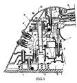
- FIG. 1 is a sectional view of a steam iron comprising a display means according to the invention
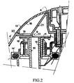
- Figure 2 shows on a larger scale a detail of the iron of Figure 1 illustrating the display means.
- the steam iron represented in FIG. 1 comprises a heating soleplate 1 comprising a vaporization chamber 2 communicating with orifices 3 for the outlet of steam formed in said soleplate, and a housing 4 whose upper region forms a handle 5 while the lower region is fixed to said sole, the front face 4 ′ of this housing being inclined forward.
- the housing 4 contains a means 6 for distributing water connected to said vaporization chamber as well as a device 7 for adjusting a thermostat 8 arranged on said soleplate and comprising a display means 9 which is in connection with a member for operation of said thermostat and which includes a display surface 11 of the operating modes of the iron, which can be read through a window 12 mounted in the wall of the housing 4.
- the upper region of the housing 4 comprises in its front part the usual members for controlling the distribution means 6 which may, for example, be of the type either drop by drop or with injection pump.
- the thermostat 8 is of the bimetal type and comprises a rotary control shaft 8 'linked to the operating member 10 which is formed by a rotary shaft 14 extending vertically towards the upper part of the housing 4 and the upper end 15 of which comprises a flange 16 transverse to the shaft, a peripheral annular zone of which carries the display surface 11.
- the rotary shaft 14 is rotated by a button 14 ', a sector of which projects from the housing 4 through a light L.
- the window 12 has an internal face 13 which is juxtaposed with the display surface 11.
- the internal face 13 is juxtaposed with the display surface 11 while providing a thin clearance ( ⁇ ) between them.
- the game ( ⁇ ) a thickness between 0.1 mm and 1 mm and preferably close to 0.5 mm.
- the internal face 13 is juxtaposed with the display surface with a slight friction between them.
- the display surface 11 and the internal face 13 are planar and extend practically in parallel planes, said internal face 13 being juxtaposed to a sector of said annular zone of the display surface 11.
- the display surface and the internal face of the window could be produced in different shapes such as semi-spherical for both, or else cylindrical or conical for the display surface and planar for the internal face of the window. .
- the window either in a transparent material, or in a translucent material which by contact with slight friction or with the film of air or water allows the reading of display area indications 11.
- the window 12 is formed by a hollow body having an external window 18 fixed to the wall of the housing 4 and an internal window 19 constituting the internal face 13 which is juxtaposed with the display surface 11.
- the hollow body can either be partially emptied of air, or filled with air, preferably dehumidified.
- the window 12 being arranged on the front face 4 ′, the external window 18 is mounted inclined and tightly fixed on a frame 20 secured to the housing 4, while the internal window 19 is mounted in a plane parallel to the flange 16.
- This internal window 19 is fixed to a skirt 21 of the frame 20 for example either by gluing or by screwing.
- the housing 4 contains, near the display means 9, a lighting lamp which by its heat radiation contributes to preventing the formation of fogging on the internal face 13 of the window.
Landscapes
- Engineering & Computer Science (AREA)
- Textile Engineering (AREA)
- Irons (AREA)
Applications Claiming Priority (2)
| Application Number | Priority Date | Filing Date | Title |
|---|---|---|---|
| FR9307564A FR2706916B1 (enExample) | 1993-06-22 | 1993-06-22 | |
| FR9307564 | 1993-06-22 |
Publications (2)
| Publication Number | Publication Date |
|---|---|
| EP0631002A1 EP0631002A1 (fr) | 1994-12-28 |
| EP0631002B1 true EP0631002B1 (fr) | 1997-10-22 |
Family
ID=9448418
Family Applications (1)
| Application Number | Title | Priority Date | Filing Date |
|---|---|---|---|
| EP19940401386 Expired - Lifetime EP0631002B1 (fr) | 1993-06-22 | 1994-06-21 | Fer à repasser à vapeur |
Country Status (4)
| Country | Link |
|---|---|
| EP (1) | EP0631002B1 (enExample) |
| DE (1) | DE69406360T2 (enExample) |
| ES (1) | ES2108393T3 (enExample) |
| FR (1) | FR2706916B1 (enExample) |
Family Cites Families (6)
| Publication number | Priority date | Publication date | Assignee | Title |
|---|---|---|---|---|
| US2582024A (en) * | 1946-06-15 | 1952-01-08 | Gen Electric | Heat setting and temperature indication in flatirons |
| US2887800A (en) * | 1957-05-27 | 1959-05-26 | Kistner Merrill Miller | Steam iron |
| DE1218629B (de) * | 1962-10-11 | 1966-06-08 | Rowenta Metallwarenfab Gmbh | Anzeigevorrichtung fuer ein elektrisches Buegeleisen |
| US3352998A (en) * | 1964-10-08 | 1967-11-14 | Matsushita Electric Industrial Co Ltd | Electric iron |
| DE2546904A1 (de) * | 1974-11-07 | 1977-07-14 | Brandenburg Elektro Veb | Elektrisch beheiztes dampfbuegeleisen |
| IT1149766B (it) * | 1982-02-17 | 1986-12-10 | Bettini Antonio | Dispositivo ad azionamento del termostato e indicazione della temperatura per ferri da stiro |
-
1993
- 1993-06-22 FR FR9307564A patent/FR2706916B1/fr not_active Expired - Fee Related
-
1994
- 1994-06-21 DE DE1994606360 patent/DE69406360T2/de not_active Expired - Fee Related
- 1994-06-21 ES ES94401386T patent/ES2108393T3/es not_active Expired - Lifetime
- 1994-06-21 EP EP19940401386 patent/EP0631002B1/fr not_active Expired - Lifetime
Also Published As
| Publication number | Publication date |
|---|---|
| DE69406360T2 (de) | 1998-08-13 |
| ES2108393T3 (es) | 1997-12-16 |
| DE69406360D1 (de) | 1997-11-27 |
| EP0631002A1 (fr) | 1994-12-28 |
| FR2706916A1 (enExample) | 1994-12-30 |
| FR2706916B1 (enExample) | 1996-02-02 |
Similar Documents
| Publication | Publication Date | Title |
|---|---|---|
| JPS5931814B2 (ja) | 反射形光電スイッチ | |
| WO2005069326A1 (fr) | Bouton tournant lumineux | |
| EP0631002B1 (fr) | Fer à repasser à vapeur | |
| FR2582117A1 (fr) | Dispositif d'horlogerie | |
| EP1131640A1 (fr) | Dispositif de visualisation du debit et de la temperature d'un fluide | |
| CA2240241A1 (en) | Flow meter | |
| FR2756067A1 (fr) | Commutateur rotatif a corps encastres pour tableau de commande d'une installation, notamment de vehicule automobile | |
| FR3081209A1 (fr) | Appareil d'eclairage a detection infrarouge avec 270 degree de couverture | |
| FR2590643A1 (fr) | Dispositif pour regler le debit et/ou la temperature de l'eau dans des robinets sanitaires | |
| FR2505944A1 (fr) | Element temporisateur pneumatique | |
| FR2658740A1 (fr) | Applicateur de liquide. | |
| FR2495770A1 (fr) | Detecteur de temperature | |
| EP0881319A1 (fr) | Socle de repos pour fer à repasser et dispositif de repassage à vapeur comportant un tel socle | |
| FR2640042A1 (fr) | Inclinometre pendulaire a lecture optique | |
| FR2515772A1 (fr) | Mitigeur a commande unique pour appareils sanitaires | |
| LU81155A1 (fr) | Procede et dispositif de detection et de controle d'un seuil de temperature dans un champ magnetique a haute frequence | |
| EP0214039A1 (fr) | Panier à linge à axes incorporés, et lave-linge muni d'un tel panier | |
| US20040028452A1 (en) | Adhesive stick | |
| FR2627583A1 (fr) | Dispositif de mesure du niveau d'un liquide dans un reservoir notamment de vehicule automobile | |
| FR2678732A1 (fr) | Thermometre a minimum et a maximum du type circulaire a aiguilles. | |
| FR2720009A1 (fr) | Manette de commande adaptable sur console de jeux électronique. | |
| FR2643710A1 (fr) | Dispositif pour guider des ondes electromagnetiques | |
| EP0010561A1 (fr) | Pistolet à eau | |
| FR2850855A1 (fr) | Moulin pour assaisonnement | |
| WO2005059484A1 (fr) | Detecteur de niveau de liquide a resistance variable |
Legal Events
| Date | Code | Title | Description |
|---|---|---|---|
| PUAI | Public reference made under article 153(3) epc to a published international application that has entered the european phase |
Free format text: ORIGINAL CODE: 0009012 |
|
| AK | Designated contracting states |
Kind code of ref document: A1 Designated state(s): DE ES GB IT |
|
| 17P | Request for examination filed |
Effective date: 19950309 |
|
| 17Q | First examination report despatched |
Effective date: 19960523 |
|
| GRAG | Despatch of communication of intention to grant |
Free format text: ORIGINAL CODE: EPIDOS AGRA |
|
| GRAH | Despatch of communication of intention to grant a patent |
Free format text: ORIGINAL CODE: EPIDOS IGRA |
|
| GRAH | Despatch of communication of intention to grant a patent |
Free format text: ORIGINAL CODE: EPIDOS IGRA |
|
| GRAA | (expected) grant |
Free format text: ORIGINAL CODE: 0009210 |
|
| AK | Designated contracting states |
Kind code of ref document: B1 Designated state(s): DE ES GB IT |
|
| GBT | Gb: translation of ep patent filed (gb section 77(6)(a)/1977) |
Effective date: 19971024 |
|
| REF | Corresponds to: |
Ref document number: 69406360 Country of ref document: DE Date of ref document: 19971127 |
|
| REG | Reference to a national code |
Ref country code: ES Ref legal event code: FG2A Ref document number: 2108393 Country of ref document: ES Kind code of ref document: T3 |
|
| ITF | It: translation for a ep patent filed | ||
| PLBE | No opposition filed within time limit |
Free format text: ORIGINAL CODE: 0009261 |
|
| STAA | Information on the status of an ep patent application or granted ep patent |
Free format text: STATUS: NO OPPOSITION FILED WITHIN TIME LIMIT |
|
| 26N | No opposition filed | ||
| PGFP | Annual fee paid to national office [announced via postgrant information from national office to epo] |
Ref country code: ES Payment date: 20010605 Year of fee payment: 8 |
|
| PGFP | Annual fee paid to national office [announced via postgrant information from national office to epo] |
Ref country code: GB Payment date: 20010618 Year of fee payment: 8 |
|
| PGFP | Annual fee paid to national office [announced via postgrant information from national office to epo] |
Ref country code: DE Payment date: 20010625 Year of fee payment: 8 |
|
| REG | Reference to a national code |
Ref country code: GB Ref legal event code: IF02 |
|
| PG25 | Lapsed in a contracting state [announced via postgrant information from national office to epo] |
Ref country code: GB Free format text: LAPSE BECAUSE OF NON-PAYMENT OF DUE FEES Effective date: 20020621 |
|
| PG25 | Lapsed in a contracting state [announced via postgrant information from national office to epo] |
Ref country code: ES Free format text: LAPSE BECAUSE OF NON-PAYMENT OF DUE FEES Effective date: 20020622 |
|
| PG25 | Lapsed in a contracting state [announced via postgrant information from national office to epo] |
Ref country code: DE Free format text: LAPSE BECAUSE OF NON-PAYMENT OF DUE FEES Effective date: 20030101 |
|
| GBPC | Gb: european patent ceased through non-payment of renewal fee |
Effective date: 20020621 |
|
| REG | Reference to a national code |
Ref country code: ES Ref legal event code: FD2A Effective date: 20030711 |
|
| PG25 | Lapsed in a contracting state [announced via postgrant information from national office to epo] |
Ref country code: IT Free format text: LAPSE BECAUSE OF NON-PAYMENT OF DUE FEES;WARNING: LAPSES OF ITALIAN PATENTS WITH EFFECTIVE DATE BEFORE 2007 MAY HAVE OCCURRED AT ANY TIME BEFORE 2007. THE CORRECT EFFECTIVE DATE MAY BE DIFFERENT FROM THE ONE RECORDED. Effective date: 20050621 |