EP0630819B1 - Abführvorrichtung einer Zigarettenverpackungsmaschine - Google Patents
Abführvorrichtung einer Zigarettenverpackungsmaschine Download PDFInfo
- Publication number
- EP0630819B1 EP0630819B1 EP94304579A EP94304579A EP0630819B1 EP 0630819 B1 EP0630819 B1 EP 0630819B1 EP 94304579 A EP94304579 A EP 94304579A EP 94304579 A EP94304579 A EP 94304579A EP 0630819 B1 EP0630819 B1 EP 0630819B1
- Authority
- EP
- European Patent Office
- Prior art keywords
- heater plate
- plate
- cigarette
- exit
- heater
- Prior art date
- Legal status (The legal status is an assumption and is not a legal conclusion. Google has not performed a legal analysis and makes no representation as to the accuracy of the status listed.)
- Expired - Lifetime
Links
- 235000019504 cigarettes Nutrition 0.000 title claims abstract description 92
- 238000012856 packing Methods 0.000 title claims abstract description 25
- 239000000853 adhesive Substances 0.000 claims description 30
- 230000001070 adhesive effect Effects 0.000 claims description 30
- 238000001816 cooling Methods 0.000 claims description 21
- 238000004806 packaging method and process Methods 0.000 claims description 12
- 230000003213 activating effect Effects 0.000 claims description 8
- 230000004913 activation Effects 0.000 claims description 5
- 238000004519 manufacturing process Methods 0.000 claims description 3
- 239000012141 concentrate Substances 0.000 abstract description 5
- 238000010438 heat treatment Methods 0.000 abstract description 5
- 239000003292 glue Substances 0.000 description 25
- 238000000034 method Methods 0.000 description 9
- 230000000694 effects Effects 0.000 description 6
- 238000012545 processing Methods 0.000 description 6
- 238000007789 sealing Methods 0.000 description 6
- 238000013021 overheating Methods 0.000 description 5
- 230000008569 process Effects 0.000 description 4
- 230000015556 catabolic process Effects 0.000 description 3
- 238000006731 degradation reaction Methods 0.000 description 3
- 239000011810 insulating material Substances 0.000 description 3
- 239000000463 material Substances 0.000 description 3
- 239000011888 foil Substances 0.000 description 2
- 238000012423 maintenance Methods 0.000 description 2
- 230000000284 resting effect Effects 0.000 description 2
- 241001016487 Pomponia Species 0.000 description 1
- 230000009471 action Effects 0.000 description 1
- 239000011230 binding agent Substances 0.000 description 1
- 238000007664 blowing Methods 0.000 description 1
- 238000005266 casting Methods 0.000 description 1
- 239000000919 ceramic Substances 0.000 description 1
- 238000010276 construction Methods 0.000 description 1
- 238000004512 die casting Methods 0.000 description 1
- 238000011143 downstream manufacturing Methods 0.000 description 1
- 238000001035 drying Methods 0.000 description 1
- 239000007788 liquid Substances 0.000 description 1
- 230000007246 mechanism Effects 0.000 description 1
- 239000002184 metal Substances 0.000 description 1
- 238000012986 modification Methods 0.000 description 1
- 230000004048 modification Effects 0.000 description 1
- 230000002250 progressing effect Effects 0.000 description 1
- 230000000750 progressive effect Effects 0.000 description 1
- 238000011160 research Methods 0.000 description 1
- 238000000926 separation method Methods 0.000 description 1
- 239000002904 solvent Substances 0.000 description 1
- XLYOFNOQVPJJNP-UHFFFAOYSA-N water Substances O XLYOFNOQVPJJNP-UHFFFAOYSA-N 0.000 description 1
Images
Classifications
-
- B—PERFORMING OPERATIONS; TRANSPORTING
- B65—CONVEYING; PACKING; STORING; HANDLING THIN OR FILAMENTARY MATERIAL
- B65B—MACHINES, APPARATUS OR DEVICES FOR, OR METHODS OF, PACKAGING ARTICLES OR MATERIALS; UNPACKING
- B65B19/00—Packaging rod-shaped or tubular articles susceptible to damage by abrasion or pressure, e.g. cigarettes, cigars, macaroni, spaghetti, drinking straws or welding electrodes
- B65B19/02—Packaging cigarettes
- B65B19/22—Wrapping the cigarettes; Packaging the cigarettes in containers formed by folding wrapping material around formers
- B65B19/223—Wrapping the cigarettes; Packaging the cigarettes in containers formed by folding wrapping material around formers in a curved path; in a combination of straight and curved paths, e.g. on rotary tables or other endless conveyors
- B65B19/226—Wrapping the cigarettes; Packaging the cigarettes in containers formed by folding wrapping material around formers in a curved path; in a combination of straight and curved paths, e.g. on rotary tables or other endless conveyors using endless conveyors having pockets, each pocket being provided with separate members, e.g. folders
-
- B—PERFORMING OPERATIONS; TRANSPORTING
- B65—CONVEYING; PACKING; STORING; HANDLING THIN OR FILAMENTARY MATERIAL
- B65B—MACHINES, APPARATUS OR DEVICES FOR, OR METHODS OF, PACKAGING ARTICLES OR MATERIALS; UNPACKING
- B65B51/00—Devices for, or methods of, sealing or securing package folds or closures; Devices for gathering or twisting wrappers, or necks of bags
- B65B51/10—Applying or generating heat or pressure or combinations thereof
-
- B—PERFORMING OPERATIONS; TRANSPORTING
- B65—CONVEYING; PACKING; STORING; HANDLING THIN OR FILAMENTARY MATERIAL
- B65B—MACHINES, APPARATUS OR DEVICES FOR, OR METHODS OF, PACKAGING ARTICLES OR MATERIALS; UNPACKING
- B65B51/00—Devices for, or methods of, sealing or securing package folds or closures; Devices for gathering or twisting wrappers, or necks of bags
- B65B51/32—Cooling, or cooling and pressing, package closures after heat-sealing
-
- B—PERFORMING OPERATIONS; TRANSPORTING
- B65—CONVEYING; PACKING; STORING; HANDLING THIN OR FILAMENTARY MATERIAL
- B65B—MACHINES, APPARATUS OR DEVICES FOR, OR METHODS OF, PACKAGING ARTICLES OR MATERIALS; UNPACKING
- B65B61/00—Auxiliary devices, not otherwise provided for, for operating on sheets, blanks, webs, binding material, containers or packages
- B65B61/002—Auxiliary devices, not otherwise provided for, for operating on sheets, blanks, webs, binding material, containers or packages for drying glued or sealed packages
-
- B—PERFORMING OPERATIONS; TRANSPORTING
- B65—CONVEYING; PACKING; STORING; HANDLING THIN OR FILAMENTARY MATERIAL
- B65B—MACHINES, APPARATUS OR DEVICES FOR, OR METHODS OF, PACKAGING ARTICLES OR MATERIALS; UNPACKING
- B65B61/00—Auxiliary devices, not otherwise provided for, for operating on sheets, blanks, webs, binding material, containers or packages
- B65B61/28—Auxiliary devices, not otherwise provided for, for operating on sheets, blanks, webs, binding material, containers or packages for discharging completed packages from machines
Definitions
- the present invention relates to an apparatus and method for packing cigarettes into cigarette packs and sealing the packs with pre-applied adhesives. More particularly, the present invention relates to sealing cigarette packages in which the packaging stock, such as the pack labels, is coated with a dry adhesive before it is supplied to the packaging machine; the apparatus provides improved means for activating and for setting the adhesive.
- Cigarette packing machines are widely used in high speed cigarette manufacturing operations.
- wet-glue wet adhesive
- cigarettes pass through successive processing steps in order to be formed into packs.
- a typical soft cigarette pack manufactured by such machines comprises an internal liner, an external label, which typically is made of coated paper, and a closure stamp.
- Water based or other solvent based or wax based adhesives are commonly used as adhesives to seal the packaging.
- wet glue is applied to the label at an edge corresponding to the sideseam of a cigarette pack and at another edge corresponding to the folded over bottom of the cigarette pack; the label is then wrapped around a bundle of cigarettes, usually 20 in number, that has already been wrapped in a foil liner.
- the wet glue is set by holding the label in place until the glue has dried. Heat may be applied in order to accelerate drying.
- wet-glue cigarette packers are widely known in the art of cigarette packaging. Exemplary versions of wet-glue packers are described in United States Patent Nos. 3,628,309 and 3,948,115, both of which are assigned to G.D. Societa per Azioni, Via Pomponia 10, 40100 Bologna, Italy, which sells commercial wet-glue packers under various model designations, including GDX-1.
- the known wet-glue-type packers typically incorporate four processing turrets, each performing predetermined processing functions while passing cigarette bundles from turret to turret.
- the fourth turret functions first to finish the label folds on the bottom of the pack and then to set the glue on that bottom panel by operating in conjunction with a heating assembly having a flat raised portion designed to contact the pack bottoms and thereby set the glue by application of heat and pressure.
- the known wet-glue-type packers also typically incorporate exit ramps, onto which the wrapped cigarette bundles enter after exiting the fourth processing turret.
- the exit ramp comprises a flat heater plate, a top pressure plate and conveying means, typically two conveyor belts.
- the heater plate and the top pressure plate operate in conjunction to set the sideseam glue as the cigarette packs are transported along the exit ramp by the conveyor belts.
- Wet-glue packing machines possess a number of known disadvantages. Among these disadvantages are: slippage, which occurs when opposing portions of the packaging stock move with respect to each other before the wet glue is set such that the desired predetermined alignment is not achieved; clogging, which occurs when the apparatus used to apply the wet glue becomes blocked or when wet glue causes the downstream processing apparatus to become clogged; and smearing, which occurs, for example, when glue seeps out from glued seams, when it bleeds through the stock, when it smears from its position or when it slings.
- packs are formed by wrapping labels having a pre-applied dry adhesive around a liner-wrapped cigarette bundle and then sealing the pack by activating the pre-applied adhesive, such as through the application of heat, and setting the adhesive, such as by cooling below the high activation temperature.
- the exit ramp apparatus is split into heating and cooling zones to thereby effect the activation and setting of the sideseam seal.
- the machine continues to process packs that are then on the exit ramp apparatus so that all of the packs are processed and transferred from the machine and are not degraded by remaining on the heater.
- exit ramp apparatus One disadvantage of the known exit ramp apparatus is that the entire exit ramp is heated, typically to high temperatures, in order to activate pre-applied adhesive or to dry wet glue on the cigarette pack sideseam. It is desirable to be able to activate and set the sideseam seal at a temperature lower than previously required.
- the surface of the exit ramp is flat and is not uniformly heated, thereby creating non-uniform seals. Because the bottom plate is typically heated by heating elements underneath, the flat surface of the bottom plate may not be uniformly heated across its surface or from one end to the other. As a result, the cigarette pack label sideseams may not be uniformly sealed. It is desirable to be able to provide a more complete and uniform sideseam seal.
- a further disadvantage of wet-glue packers is heat degradation or burning that occurs when packs remain on the heated exit ramp after the packer is shut off.
- EP-A-0 514 203 discloses apparatus for sealing a cigarette pack by activation of a pre-applied adhesive.
- the apparatus includes an activation turret in which the adhesive on the bottom of a wrapped bundle of cigarettes is activated by heat and then cooled to set the adhesive, and an exit ramp heater which comprises a heated plate against which the sideseam of the bundles are urged by a patter plate to activate the adhesive and a cooling plate against which the bundles are urged to set the adhesive.
- US-A-3 599 394 discloses apparatus for heat sealing a sheet of heat sealable material around a package. The material in place around the package passes over heated ribs which cause the material to shrink in the region of the ribs.
- a cigarette packing machine exit apparatus for activating pre-applied adhesive on sideseams of cigarette packs, comprising: a heater plate; and a conveyor for transporting cigarette packs along an exit apparatus path comprising the heater plate so that the sideseams of the cigarette packs contact at least a portion of the top surface of the heater plate, in which the top surface of the heater plate comprises a plurality of contact surfaces characterised in that the heater plate is pivotally mounted to be movable between an operating position and a pivoted position and in that the apparatus further comprises: a pivot axis to which the heater plate is pivotally mounted; and pivot motion means for moving the heater plate about the pivot axis.
- the upper surface of the heater place (the contact surface) is preferably contoured to effect a more complete seal on the cigarette pack sideseams.
- the pivoted heater retraction mechanism reduces heat degradation of packs left on the heater plate for extended periods.
- the contoured surface of the heater plate preferably has raised ridges that are oriented diagonally on the contact surface.
- the raised ridges function as pressure points to concentrate the heat as the cigarette pack sideseams contact the heater plate's contact surface, thereby reducing the temperature needed to activate the binder on the seams.
- the diagonal orientation of the preferred ridges effectively serves to move the pressure points across the sides of the cigarette packs and along each sideseam from one end to the other as the packs progress along the heater plate.
- the heater plate is pivotally mounted such that it can be elevated at one longitudinal end while being pivoted about an axis at the other end, enabling one end of the heater plate to be raised and retracted.
- the heater plate is mounted such that it can be elevated at both longitudinal ends, enabling the entire heater plate to be raised and retracted. This raising and retracting feature is utilized when the cigarette packer is stopped, in order to create a spatial separation of the packs from the heater plate. Raising the heater plate serves to push the cigarette packs that are on the exit ramp upward. Then, when the plate is retracted back to its operating position, the cigarette packs are removed from contact with the heater plate by being held in the raised position by exit ramp conveyor belts.
- a sealed cigarette pack is formed by using a cigarette packer and dry adhesives, such as described in co-pending EP-A-0 514 203.
- the cigarette packer wraps a bundle of cigarettes first with a foil liner and then with a label having a pre-applied dry adhesive.
- the cigarette packer then forms seals, first at the pack bottom using a heat-applying processing turret and then at the pack sides using a heat-applying portion of an exit ramp.
- the heated portion of the exit ramp bottom plate (the heater plate) comprises ridges that are formed on its surface at a diagonal to the longitudinal direction of the plate. These raised ridges function as pressure points to concentrate the heat from the heater plate on reduced areas of the cigarette pack sideseam that contact the ridges.
- the heater plate when the cigarette packing machine is shut off, the heater plate is raised and then returned to its original position.
- the heater plate is raised at one end while being pivoted at the other end, and in another embodiment the heater plate is raised at both ends. The raising of the heater plate pushes the cigarette packs being conveyed along the exit apparatus upward so that the subsequent retraction of the heater plate leaves the cigarette packs held by the tension of the conveyor belts in a raised position. As a result, a gap is created such that the packs are separated from and are not heated by the heater plate when the packing machine is not in use.
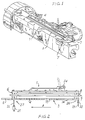
- FIG. 1 shows a known wet-glue cigarette packer exit ramp apparatus 1 that has been modified in accordance with the present invention.
- Cigarette packs enter onto the exit ramp after having been wrapped in labels by the processing turrets.
- These labels as disclosed in EP-A-0 514 203, preferably have a heat-activated dry adhesive pre-applied at edges corresponding to the sideseam of the cigarette pack and the folded over bottom of the cigarette pack, such that the labels are sealed around each pack by application of heat.
- the exit ramp apparatus 1 of the present invention comprises a bottom plate apparatus 3 comprising a heater plate 4 and a cooling plate 5, a top pressure plate 6 and conveying means 7.
- the conveying means can be any means for transporting the cigarette packs along the bottom plate 3, such as an inclined vibrating bottom plate or a pocket chain, but preferably comprises side conveyor belts 7.
- Each cigarette pack enters onto the exit ramp 1, sideways, resting on the unsealed label sideseam.
- Each pack is conveyed longitudinally along the bottom plate 3 from entrance end 26 to exit end 27 by conveyor belts 7 that impinge upon each pack at its top and bottom. Any number of conveyor belts 7 may be used in order to effect the longitudinal entrance 26 to exit 27 motion.
- the top pressure plate 6 applies intermittent downward pressure by patting down onto the upward-facing sides of the cigarette packs so that the opposite sides of the packs are contacted with the bottom plate 3. In this way, the downward-facing side of each cigarette pack contacts the bottom plate 3, both at the heater plate portion 4 and at the cooling plate portion 5.
- the sideseam adhesive is thus both activated and set uniformly.
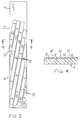
- the heater plate 4 of the bottom plate apparatus 3 comprises raised contact surfaces 10 that are formed on its otherwise flat surface. This novel heater plate 4 is shown in more detail in FIGS. 3-6. As the packs are moved along the heater plate 4, the packs contact the plate only at the raised positions of the bottom plate. These raised contact surfaces 10 serve as pressure points to concentrate the heat from the heater 4 onto the label sideseam.
- the sideseam seal can be activated at lower temperatures than previously required with a completely flat heater plate surface.
- One result of concentrating the heat on these contact surfaces is that less heat from the heater plate is required to activate the seal on the cigarette packs.
- elongated ridges 10 in the heater plate 4 are formed parallel to each other and at a diagonal to the longitudinal direction of the plate. These diagonal elongated ridges 10 effectively serve to move the raised pressure points across the sides of the cigarette packs as the packs are moved in the longitudinal direction along the heater plate 4. In this way, concentrated heat is applied along the seal, progressing from one end of the seal to the other.
- elongated ridges may be formed on the bottom plate such that the ridged portions of the bottom plate form intersecting crossing patterns, such as an "X" (not shown).
- a series of shortened ridges is formed so that the ridges are parallel to each other in the longitudinal direction of the heater plate but are offset slightly from one another such that the row of short ridges is generally at a diagonal to the longitudinal direction of the heater plate (not shown).
- Other alternative ridging patterns also can be formed such that the raised contact portions are in a generally angular pattern such that the raised pressure points move across the sides of the packs as the packs progress along the bottom plate.
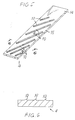
- the raised contact surfaces may be manufactured using any known process. Die-casting can be used to form elongated narrow ridges 10 as part of the surface of the heater plate 4 at the time of its manufacture. Rather than casting a flat bottom plate surface, a ridged bottom plate surface is cast. Such ridges are shown in FIGS. 5 and 6.
- the preferred method of creating the narrow raised contact surfaces 10 is by beveling elongated grooves 12 into the flat surface of the heater plate 4. These grooves 12 are shown in cross-section in FIG. 4. After beveling, the remaining raised portions 10 function as the pressure points that concentrate the bottom plate heat onto the cigarette pack sideseam as the pack moves along the heater plate 4. This beveling method may be used to modify the existing bottom plates of known exit ramps.
- the beveled heater plate 4 may be further modified by being inlayed with a heat insulating material between the ridges 10 (not shown).
- a heat insulating material such as a high temperature plastic, is poured into the grooves and allowed to dry.
- pre-formed ceramic inserts may be placed between ridges 10. The heat insulating material helps to shield the cigarette packs 8 resting on the bottom heater plate ridges 10 from the convective heat of the bottom plate, thus preventing convective overheating of the cigarette packs.
- the contact ridges 10 are formed by beveling grooves 12 approximately 750mm (30/1000") deep, approximately 15mm (5/8") wide and approximately 3mm (1/8") apart. In effect, this creates a profile with contact points each 750 mm (30/1000") high and 3mm (1/8") wide, and spaced 15mm (5/8") apart.
- the raised contact ridges 10 may be formed by beveling grooves 12 with different, more suitable depth, width and spacing.
- the contact surfaces 10 preferably do not extend along the entire length of the heater plate 4, but rather extend along the portion of the length closest to the exit end 27, preferably the last 80% of the length of the heater plate 4.
- the first portion 14 of the heater plate, closest to entrance end 26, is flat, without any grooves or raised portions, as shown in FIGS. 3 and 5.
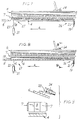
- the cooling portion may be a separate plate 5, as shown in FIGS. 7 and 8, or may be a continuous portion of the exit ramp bottom plate 3 downstream of the heater portion 4 of the exit ramp bottom plate.
- the cooling portion preferably is a combination having two sequential components.
- the first part preferably is a cooled section at the exit end of the heated plate 4 and the second part preferably is a separate cooling plate 5 downstream of the heated plate 4.
- the separate cooling plate 5 may be a separate metal plate generally at ambient temperature, i.e. without forced cooling.
- the cooling plate 5 preferably is cooled by external means, such as by passing cool air or liquid under it, or by some other cooling method.
- the cooling portion of the exit ramp may be flat or may be contoured in one of the ridging patterns discussed above.
- the heater plate 4 when the packing machine is shut off, the heater plate 4 is raised and then is returned to its original position.
- the heater plate 4 is raised at one end while being pivoted at the other end.
- the heater plate 4 is raised at both ends. Raising and retraction of the heater plate in the preferred embodiment are illustrated in FIGS. 7 and 8 respectively. Raising the heater plate 4 pushes the cigarette packs 8 that are being conveyed along the exit apparatus upward so that the subsequent retraction of the heater plate 4 to its original position leaves the packs 8 held in a raised position by the tension of the conveyor belts 7.
- a gap 18 is created between the heater plate 4 and the cigarette packs 8 such that the packs 8 are spatially separated from and are generally not heated by the heater plate 4 when the packing machine is not in use.
- the spatial gap between the packs 8 and the heater plate 4 reduces the heat transferred to the packs 8, thus protecting the packs 8 from over-heating by the heater plate 4 and the resulting heat degradation.
- cool air is blown through the gap 18 between the packs 8 and the heater plate 4.to further cool the packs 8.
- creating the gap 18 prevents conductive overheating of the packs contacting the heater plate
- blowing cool air through the gap 18 prevents convective overheating of the packs 8 by cooling the heat emanating from the heater plate 4.
- the present invention also comprises a top pressure plate 6 that pats down on the upward-facing sides of the cigarette packs 8 so that the opposite sides of the cigarette packs contact the bottom plate 3.
- the top pressure plate provides fixed pressure intermittently upon the packs 8 so that they contact the bottom plate surface.
- the top pressure plate 6 is spring-loaded so that the packs 8 are not crushed by the downward pressure of the top pressure plate 6.
- the top pressure plate is self-leveling so that pressure by the top plate 6 is applied to the cigarette packs 8 uniformly, causing the entire downward-facing side of each cigarette pack to contact the bottom plate 3.
- Self-leveling may be accomplished by a ball-and-socket mount, by a swivel mount or by some other suitable mounting means.
- the spring-loaded top pressure plate 6 is also retractable, as shown in FIG. 9. It is preferable that top plate 6 be retracted prior to the raising of the bottom plate 4 so that cigarette packs 8 on the exit ramp are not crushed or deformed by opposing action of the two plates.
- Any switching apparatus may be used to turn the packing machine on or off -- such as any of the known electrical and mechanical switches.
- any apparatus may be used for raising, retracting and pivoting the heater plate 4.
- a long bolt 19 and a high tension spring 20 may be used to create a pivot axis.
- a double acting air cylinder 21 and a connecting rod 22 may be used to raise and retract that end of the heater plate 4.
- the exit ramp bottom plate 4 is raised at the exit end 27 of the exit ramp and is pivoted at the entrance end 26 of the exit ramp.
- raising of the heater plate 4 is done at both the entrance end 26 and the exit end 27 of the exit ramp heater plate 4, preferably by the above apparatus.
- any apparatus may be used for raising and retracting the top pressure plate 6.
- a shaft 23 connected to the top pressure plate 6 may be equipped with an air cylinder assembly 24 to retract the plate.
- the top pressure plate air cylinder 24 when the packing machine is switched off, the top pressure plate air cylinder 24 is activated to retract the top pressure plate 6, and then the bottom plate air cylinder 21 is activated to raise and lower the exit end 27 of the heater plate 4 in the directions indicated by reference arrows B and C in FIGS. 7 and 8, respectively.
- the entrance end 26 of the heater plate 4 remains pivotally mounted such that it pivots about spring 20 when the exit end 27 is raised and lowered.
- a bottom plate air cylinder on each end of the heater plate is activated to raise and lower the entire heater plate. Later, when the packing machine is restarted, the top pressure plate air cylinder 24 is reactivated so that the top pressure plate 6 moves back to its functional position and in the process pushes the suspended cigarette packs 8 back down into contact with the bottom plate 4.
- the air cylinders 21, 24 are activated preferably by an electric solenoid valve linked through a timer relay to the GDX-1 packer stop circuit. Alternatively, any other suitable means for activating the air cylinders in this sequence may be used.
- the bottom plate air cylinder 21 raises the exit end 27 of the exit ramp's heater plate 4 by a preferred distance of at least one-half inch.
- both ends of the heater plate are raised by a preferred distance of at least one-half inch.
- the exit apparatus of the invention finds particular application at the exit end of a turret type cigarette packer such as a GDX-1.
Landscapes
- Engineering & Computer Science (AREA)
- Mechanical Engineering (AREA)
- Wrapping Of Specific Fragile Articles (AREA)
Claims (20)
- Austragvorrichtung (1) einer Zigarettenverpackungsmaschine zum Aktivieren von voraufgetragenem Klebstoff auf Seitennähten von Zigarettenpackungen, die folgendes aufweist:eine Heizplatte (4) undeinen Förderer (7) zum Befördern von Zigarettenpackungen an einer Austragsvorrichtungsbahn entlang, die die Heizplatte aufweist, sodass die Seitennähte der Zigarettenpackungen wenigstens einen Teil der Oberseite der Heizplatte berühren, wobei die Oberseite der Heizplatte eine Mehrzahl von Kontaktflächen (10) aufweist, dadurch gekennzeichnet, dass die Heizplatte (4) drehbar montiert ist, um zwischen einer Betriebsposition und einer Drehposition bewegbar zu sein, und dass die Vorrichtung des Weiteren Folgendes aufweist:eine Drehachse, an der die Heizplatte drehbar montiert ist, undein Drehbewegungsmittel (21, 22) zum Bewegen der Heizplatte um die Drehachse.
- Vorrichtung (1) nach Anspruch 1, bei der der Förderer eine Mehrzahl von Förderbändern (7) aufweist.
- Vorrichtung (1) nach Anspruch 1 oder Anspruch 2, bei der der Förderer zwei einander gegenüberliegende Förderbänder (7) aufweist, die jeweils über die gesamte Längslänge der Austragsvorrichtungsbahn verlaufen.
- Vorrichtung (1) nach einem der vorangehenden Ansprüche, bei dem die Austragsvorrichtungsbahn des Weiteren Folgendes aufweist:eine Kühlplatte (5), die so angeordnet ist, dass das Auftragsende der Kühlplatte (5) auf das Austragsende der Heizplatte (4) ausgerichtet ist, sodass der Förderer (7) Zigarettenpackungen vom Austragsende der Heizplatte zum Auftragsende der Kühlplatte hin befördern kann.
- Vorrichtung (1) nach Anspruch 4, bei der die Drehachse an das Auftragsende der Heizplatte angrenzt.
- Vorrichtung (1) nach einem der vorangehenden Ansprüche, die des Weiteren einen Schalter zum Schalten der Verpackungsmaschine zwischen Betriebszustand und Aus-Zustand aufweist, wobei das Drehbewegungsmittel (21, 22) bewirkt, dass die Heizplatte (4) nach oben gedreht wird, wenn der Schalter aktiviert wird, um die Verpackungsmaschine auf den Aus-Zustand zu schalten.
- Vorrichtung (1) nach Anspruch 6, bei der das Drehbewegungsmittel (21, 22) bewirkt, dass die Heizplatte (4) wieder in ihre Betriebsposition zurückkehrt, nachdem das Drehbewegungsmittel oder das Hebemittel bewirkt, dass die Heizplatte nach oben gedreht wird.
- Vorrichtung (1) nach einem der vorangehenden Ansprüche, bei der der Förderer eine Mehrzahl einander gegenüberliegender Förderbänder (7) aufweist, die auf gegenüberliegenden transversalen Seiten der Heizplatte (4) montiert sind und dergestalt montiert sind, dass sie die Packungen von der Heizplatte räumlich getrennt tragen, nachdem das Drehbewegungsmittel (21, 22) bewirkt, dass die Heizplatte in ihre Betriebsposition zurückkehrt.
- Vorrichtung (1) nach einem der vorangehenden Ansprüche, bei der die Kontaktflächen Kontaktrippen (10) aufweisen, die parallel zueinander sind und diagonal zur Austragsvorrichtungsbahn ausgerichtet sind.
- Vorrichtung nach Anspruch 9, bei der die Kontaktrippen einander schneiden, um eine Mehrzahl von Kreuzungsmustern zu ergeben.
- Vorrichtung (1) nach Anspruch 9 oder Anspruch 10, bei der sich die Kontaktrippen (10) an weniger als der gesamten Länge der Heizplatte (4) entlang erstrecken.
- Vorrichtung nach einem der Ansprüche 9 bis 11, die des Weiteren Wärmeisoliermittel zwischen den Kontaktrippen (10) zum Isolieren der Packungen von der Oberseite der Heizplatte aufweist.
- Vorrichtung nach einem der vorangehenden Ansprüche, bei der die Kontaktflächen (10) eine Mehrzahl parallel zueinander und zur Austragsvorrichtungsbahn liegender gekürzter Kontaktrippen aufweisen, wobei die Mehrzahl in Bezug auf die Austragsvorrichtungsbahn allgemein diagonal angeordnet ist.
- Vorrichtung (1) nach einem der vorangehenden Ansprüche, die des Weiteren eine obere Druckplatte (6) aufweist, die montiert ist, um Druck auf die der Oberseite der Heizplatte (4) gegenüberliegenden Zigarettenpackungen auszuüben.
- Vorrichtung (1) nach Anspruch 14, bei der die obere Druckplatte (6) gefedert ist.
- Vorrichtung (1) nach Anspruch 14, bei der die obere Druckplatte (6) schwenkbar montiert ist, um selbstausgleichend zu sein.
- Vorrichtung (1) nach einem der Ansprüche 14 bis 16, bei der die obere Druckplatte (6) montiert ist, um zwischen einer Betriebsposition und einer zurückgezogenen Position bewegbar zu sein, und die des Weiteren eine Rückziehvorrichtung (24) zum Bewegen der oberen Druckplatte zwischen der Betriebsposition und der zurückgezogenen Position und einen Schalter zum Schalten der Verpackungsmaschine zwischen einem Betriebs- und einem Aus-Zustand aufweist, wobei die Rückziehvorrichtung bewirkt, dass die obere Druckplatte zurückgezogen wird, wenn der Schalter aktiviert wird, um die Verpackungsmaschine in den Aus-Zustand zu schalten.
- Vorrichtung zur Herstellung von Zigarettenpackungen bestehend aus Einschlagmaterial, das auf einem Teil seiner Innenseite mit einem voraufgetragenen trockenen Heißklebstoff beschichtet ist, wobei die Vorrichtung Folgendes aufweist:eine Bündelvorrichtung zum Formen eines Bündels von hüllstoffumhüllten Zigaretten, wobei jedes Bündel so unhüllt ist, dass die Innenseite des Einschlagmaterials an die Zigaretten angrenzt und jedes der Bündel eine Seitennaht hat, die voraufgetragenen trockenen Heißklebstoff aufweist, mit dem ein Teil der Innenseite des Einschlagmaterials beschichtet ist,Austragsvorrichtung nach einem der Ansprüche 1 oder 17 zum Aktivieren des voraufgetragenen trockenen Heißklebstoffs der Seitennähte der Bündel, indem die Seitennähte mit der Mehrzahl von Kontaktflächen (10) der Heizplatte (4) in Berührung gebracht werden, wobei die Austragsvorrichtung eine Kühlplatte (5) nach Anspruch 4 aufweist zum Härten des voraufgetragenen trockenen wärmeaktivierten Klebstoffs der Seitennähte der hüllstoffumhüllten Bündel, indem jede der Seitennähte mit der Kühlplatte (5) in Berührung gebracht wird, wobei die Kühlplatte (5) nach der Heizplatte (4) angeordnet ist.
- Vorrichtung nach Anspruch 18, die Folgendes aufweist:eine Zuführvorrichtung zum Befördern des Einschlagmaterials an einer Zuführbahn entlang undeine Sammelvorrichtung zum Zusammentragen einer Mehrzahl von Zigaretten, die jeweils in jede Zigarettenpackung eingeschlossen werden soll,
wobei die Bündelvorrichtung nach der Zuführvorrichtung und der Sammelvorrichtung angeordnet ist. - Vorrichtung nach Anspruch 18 oder 19 in der Form einer Zigarettenverpackungsmaschine des Revolvertyps, bei der sich die Heizplatte (4) in der Nähe des Aktivierungsrevolvers befindet, sodass die Heizplatte Wärme auf die Seitennaht jedes einschlagumhüllten Bündels ausstrahlt, wenn es sich auf der Austragsvorrichtung (1) befindet.
Applications Claiming Priority (2)
| Application Number | Priority Date | Filing Date | Title |
|---|---|---|---|
| US81974 | 1993-06-23 | ||
| US08/081,974 US5447014A (en) | 1991-05-15 | 1993-06-23 | Cigarette packing machine exit apparatus |
Publications (2)
| Publication Number | Publication Date |
|---|---|
| EP0630819A1 EP0630819A1 (de) | 1994-12-28 |
| EP0630819B1 true EP0630819B1 (de) | 2000-05-03 |
Family
ID=22167593
Family Applications (1)
| Application Number | Title | Priority Date | Filing Date |
|---|---|---|---|
| EP94304579A Expired - Lifetime EP0630819B1 (de) | 1993-06-23 | 1994-06-23 | Abführvorrichtung einer Zigarettenverpackungsmaschine |
Country Status (5)
| Country | Link |
|---|---|
| US (1) | US5447014A (de) |
| EP (1) | EP0630819B1 (de) |
| AT (1) | ATE192394T1 (de) |
| CZ (1) | CZ150894A3 (de) |
| DE (1) | DE69424226D1 (de) |
Families Citing this family (12)
| Publication number | Priority date | Publication date | Assignee | Title |
|---|---|---|---|---|
| DE19535649A1 (de) * | 1995-09-26 | 1997-03-27 | Focke & Co | Verfahren und Vorrichtung zum Herstellen von Verpackungen mit einer Außenumhüllung aus Papier oder dergleichen |
| ES2249584T3 (es) * | 2001-06-01 | 2006-04-01 | Colgate-Palmolive Company | Envoltorio para pastillas de jabon. |
| ITBO20050167A1 (it) * | 2005-03-17 | 2005-06-16 | Gd Spa | Metodo e dispositivo per il confezionamento di pacchetti per articoli da fumo |
| US9902517B2 (en) * | 2013-11-01 | 2018-02-27 | Frito-Lay North America, Inc. | Apparatus and method for a structurally resilient package |
| US9840346B2 (en) | 2013-11-01 | 2017-12-12 | Frito-Lay North America, Inc. | Method and apparatus for making a structurally resilient package |
| USD868859S1 (en) * | 2018-06-11 | 2019-12-03 | Baron Buehring | Side panel for high capacity dispensing unit |
| USD869527S1 (en) * | 2018-06-11 | 2019-12-10 | Baron Buehring | Side panel for high capacity dispensing unit |
| USD868858S1 (en) * | 2018-06-11 | 2019-12-03 | Baron Buehring | Side panel for high capacity dispensing unit |
| USD873317S1 (en) * | 2018-06-11 | 2020-01-21 | Baron Buehring | Side panel for high capacity dispensing unit |
| USD868860S1 (en) * | 2018-06-11 | 2019-12-03 | Baron Buehring | Side panel for high capacity dispensing unit |
| CN111846455B (zh) * | 2020-08-14 | 2025-07-29 | 上海新平科机电科技有限公司 | 一种条包烟透明纸熨烫装置 |
| MX2023006080A (es) * | 2020-12-02 | 2023-06-06 | Nestle Sa | Sellado a presion de multiples etapas de sustratos metalizados. |
Family Cites Families (10)
| Publication number | Priority date | Publication date | Assignee | Title |
|---|---|---|---|---|
| US2638724A (en) * | 1945-12-19 | 1953-05-19 | Molins Machine Co Ltd | Method of and apparatus for sealing wrappers |
| US2480501A (en) * | 1946-09-25 | 1949-08-30 | Reynolds Metals Co | Means for producing cigarette packages |
| US2697474A (en) * | 1951-07-31 | 1954-12-21 | American Mach & Foundry | Hot seal cooling mechanism |
| US3010267A (en) * | 1959-05-25 | 1961-11-28 | Chicago Carton Co | Carton sealing apparatus |
| US3140971A (en) * | 1962-03-14 | 1964-07-14 | Package Machinery Co | Heat sealing channel |
| US3599394A (en) * | 1969-08-26 | 1971-08-17 | Triangle Package Machinery Co | Automatic wrapping machines |
| DE2219540A1 (de) * | 1972-04-21 | 1973-10-31 | Niepmann & Co Maschf Fr | Verfahren und vorrichtung zur herstellung von zigarettenpackungen |
| IT982254B (it) * | 1973-03-05 | 1974-10-21 | Gd Spa | Apparecchiatura di uscita dei pro dotti da una linea di incarto e confezionamento di detti prodot ti particolarmente pacchetti di sigarette e simili |
| US4362593A (en) * | 1980-11-17 | 1982-12-07 | Nordson Corporation | Walking-beam band sealer |
| CA2068568A1 (en) * | 1991-05-15 | 1992-11-16 | John M. Adams | Cigarette packaging machine and apparatus |
-
1993
- 1993-06-23 US US08/081,974 patent/US5447014A/en not_active Expired - Fee Related
-
1994
- 1994-06-20 CZ CZ941508A patent/CZ150894A3/cs unknown
- 1994-06-23 DE DE69424226T patent/DE69424226D1/de not_active Expired - Lifetime
- 1994-06-23 AT AT94304579T patent/ATE192394T1/de not_active IP Right Cessation
- 1994-06-23 EP EP94304579A patent/EP0630819B1/de not_active Expired - Lifetime
Also Published As
| Publication number | Publication date |
|---|---|
| CZ150894A3 (en) | 1995-12-13 |
| US5447014A (en) | 1995-09-05 |
| ATE192394T1 (de) | 2000-05-15 |
| DE69424226D1 (de) | 2000-06-08 |
| EP0630819A1 (de) | 1994-12-28 |
Similar Documents
| Publication | Publication Date | Title |
|---|---|---|
| EP0630819B1 (de) | Abführvorrichtung einer Zigarettenverpackungsmaschine | |
| KR100233230B1 (ko) | 담배 팩과 그의 제조방법 및 제조장치 | |
| KR100454349B1 (ko) | 멀티팩포장장치 | |
| US4475653A (en) | Package and process of forming same | |
| FI89149C (fi) | Foerfarande och anordning foer emballering av rullar, i synnerhet pappersrullar, med foerpackningsomslag | |
| CA1272632A (en) | Carrying handle for a can carton | |
| EP0273240A2 (de) | Apparat zum Falten und Schliessen eines aus Hüllmaterial bestehenden Abschnitts um einen zu verpackenden Artikel | |
| DE68921225D1 (de) | Vorrichtung zum aufbringen von verpackungshülsen. | |
| EP0351553A1 (de) | Siegelvorrichtung für sich überlappende Endlappen einer thermoplastischen Umhüllung für Verpackungen, insbesondere für Zigarettenverpackungen | |
| US2638724A (en) | Method of and apparatus for sealing wrappers | |
| CN101272959A (zh) | 用于对包装盒进行热处理的装置 | |
| EP0394579A1 (de) | Doppelstationseinwickelmaschine | |
| KR950000538A (ko) | 포장재 제거장치 | |
| EP0161542B1 (de) | Faltvorrichtung mit Hin- und Herbewegung für Verpackungsmaschinen | |
| CA2004082A1 (en) | Apparatus for closing a package around an article to be packaged | |
| US4792246A (en) | Apparatus for raised printing | |
| EP0058652A1 (de) | Verfahren und Vorrichtung zum Verpacken von Speiseeisartikeln in Einzelhüllen | |
| US5871431A (en) | Plant for manufacturing cardboard containers and the manufacturing method for said containers | |
| NL8303012A (nl) | Werkwijze en inrichting voor het verpakken van ruimtelijke voortbrengselen. | |
| KR20000069726A (ko) | 압축 가능한 재료를 포장하기 위한 방법 및 그 장치 | |
| CA2033616A1 (en) | Equipment for folding and joining boxes made from flat or basically flat materials | |
| JP4005196B2 (ja) | スティック状シール袋の自動整列装置 | |
| US4671045A (en) | Method and assembly for sealing articles | |
| US6505458B1 (en) | Method and machine for packing a group of products | |
| EP4684943A1 (de) | Siegelvorrichtung, schlauchbeutelverpackungsmaschine und verfahren zur herstellung einer siegelnaht |
Legal Events
| Date | Code | Title | Description |
|---|---|---|---|
| PUAI | Public reference made under article 153(3) epc to a published international application that has entered the european phase |
Free format text: ORIGINAL CODE: 0009012 |
|
| AK | Designated contracting states |
Kind code of ref document: A1 Designated state(s): AT BE CH DE DK ES FR GB GR IE IT LI LU MC NL PT SE |
|
| RAX | Requested extension states of the european patent have changed |
Free format text: SI PAYMENT 940721 |
|
| 17P | Request for examination filed |
Effective date: 19950502 |
|
| 17Q | First examination report despatched |
Effective date: 19960802 |
|
| GRAG | Despatch of communication of intention to grant |
Free format text: ORIGINAL CODE: EPIDOS AGRA |
|
| GRAG | Despatch of communication of intention to grant |
Free format text: ORIGINAL CODE: EPIDOS AGRA |
|
| GRAH | Despatch of communication of intention to grant a patent |
Free format text: ORIGINAL CODE: EPIDOS IGRA |
|
| GRAH | Despatch of communication of intention to grant a patent |
Free format text: ORIGINAL CODE: EPIDOS IGRA |
|
| GRAA | (expected) grant |
Free format text: ORIGINAL CODE: 0009210 |
|
| AK | Designated contracting states |
Kind code of ref document: B1 Designated state(s): AT BE CH DE DK ES FR GB GR IE IT LI LU MC NL PT SE |
|
| AX | Request for extension of the european patent |
Free format text: SI PAYMENT 19940721 |
|
| PG25 | Lapsed in a contracting state [announced via postgrant information from national office to epo] |
Ref country code: NL Free format text: LAPSE BECAUSE OF FAILURE TO SUBMIT A TRANSLATION OF THE DESCRIPTION OR TO PAY THE FEE WITHIN THE PRESCRIBED TIME-LIMIT Effective date: 20000503 Ref country code: LI Free format text: LAPSE BECAUSE OF FAILURE TO SUBMIT A TRANSLATION OF THE DESCRIPTION OR TO PAY THE FEE WITHIN THE PRESCRIBED TIME-LIMIT Effective date: 20000503 Ref country code: IT Free format text: LAPSE BECAUSE OF FAILURE TO SUBMIT A TRANSLATION OF THE DESCRIPTION OR TO PAY THE FEE WITHIN THE PRESCRIBED TIME-LIMIT;WARNING: LAPSES OF ITALIAN PATENTS WITH EFFECTIVE DATE BEFORE 2007 MAY HAVE OCCURRED AT ANY TIME BEFORE 2007. THE CORRECT EFFECTIVE DATE MAY BE DIFFERENT FROM THE ONE RECORDED. Effective date: 20000503 Ref country code: GR Free format text: LAPSE BECAUSE OF NON-PAYMENT OF DUE FEES Effective date: 20000503 Ref country code: FR Free format text: LAPSE BECAUSE OF FAILURE TO SUBMIT A TRANSLATION OF THE DESCRIPTION OR TO PAY THE FEE WITHIN THE PRESCRIBED TIME-LIMIT Effective date: 20000503 Ref country code: CH Free format text: LAPSE BECAUSE OF FAILURE TO SUBMIT A TRANSLATION OF THE DESCRIPTION OR TO PAY THE FEE WITHIN THE PRESCRIBED TIME-LIMIT Effective date: 20000503 Ref country code: BE Free format text: LAPSE BECAUSE OF FAILURE TO SUBMIT A TRANSLATION OF THE DESCRIPTION OR TO PAY THE FEE WITHIN THE PRESCRIBED TIME-LIMIT Effective date: 20000503 Ref country code: AT Free format text: LAPSE BECAUSE OF FAILURE TO SUBMIT A TRANSLATION OF THE DESCRIPTION OR TO PAY THE FEE WITHIN THE PRESCRIBED TIME-LIMIT Effective date: 20000503 |
|
| REF | Corresponds to: |
Ref document number: 192394 Country of ref document: AT Date of ref document: 20000515 Kind code of ref document: T |
|
| PGFP | Annual fee paid to national office [announced via postgrant information from national office to epo] |
Ref country code: DK Payment date: 20000512 Year of fee payment: 7 |
|
| REG | Reference to a national code |
Ref country code: CH Ref legal event code: EP |
|
| PGFP | Annual fee paid to national office [announced via postgrant information from national office to epo] |
Ref country code: IE Payment date: 20000517 Year of fee payment: 7 Ref country code: AT Payment date: 20000517 Year of fee payment: 7 |
|
| PGFP | Annual fee paid to national office [announced via postgrant information from national office to epo] |
Ref country code: FR Payment date: 20000518 Year of fee payment: 7 |
|
| PGFP | Annual fee paid to national office [announced via postgrant information from national office to epo] |
Ref country code: SE Payment date: 20000519 Year of fee payment: 7 Ref country code: MC Payment date: 20000519 Year of fee payment: 7 |
|
| PGFP | Annual fee paid to national office [announced via postgrant information from national office to epo] |
Ref country code: CH Payment date: 20000522 Year of fee payment: 7 |
|
| PGFP | Annual fee paid to national office [announced via postgrant information from national office to epo] |
Ref country code: GB Payment date: 20000523 Year of fee payment: 7 |
|
| PGFP | Annual fee paid to national office [announced via postgrant information from national office to epo] |
Ref country code: NL Payment date: 20000524 Year of fee payment: 7 Ref country code: DE Payment date: 20000524 Year of fee payment: 7 |
|
| REG | Reference to a national code |
Ref country code: IE Ref legal event code: FG4D |
|
| PGFP | Annual fee paid to national office [announced via postgrant information from national office to epo] |
Ref country code: ES Payment date: 20000608 Year of fee payment: 7 |
|
| REF | Corresponds to: |
Ref document number: 69424226 Country of ref document: DE Date of ref document: 20000608 |
|
| PGFP | Annual fee paid to national office [announced via postgrant information from national office to epo] |
Ref country code: BE Payment date: 20000615 Year of fee payment: 7 |
|
| PGFP | Annual fee paid to national office [announced via postgrant information from national office to epo] |
Ref country code: LU Payment date: 20000622 Year of fee payment: 7 |
|
| PG25 | Lapsed in a contracting state [announced via postgrant information from national office to epo] |
Ref country code: SE Free format text: LAPSE BECAUSE OF FAILURE TO SUBMIT A TRANSLATION OF THE DESCRIPTION OR TO PAY THE FEE WITHIN THE PRESCRIBED TIME-LIMIT Effective date: 20000803 Ref country code: PT Free format text: LAPSE BECAUSE OF FAILURE TO SUBMIT A TRANSLATION OF THE DESCRIPTION OR TO PAY THE FEE WITHIN THE PRESCRIBED TIME-LIMIT Effective date: 20000803 Ref country code: DK Free format text: LAPSE BECAUSE OF FAILURE TO SUBMIT A TRANSLATION OF THE DESCRIPTION OR TO PAY THE FEE WITHIN THE PRESCRIBED TIME-LIMIT Effective date: 20000803 |
|
| PG25 | Lapsed in a contracting state [announced via postgrant information from national office to epo] |
Ref country code: DE Free format text: LAPSE BECAUSE OF FAILURE TO SUBMIT A TRANSLATION OF THE DESCRIPTION OR TO PAY THE FEE WITHIN THE PRESCRIBED TIME-LIMIT Effective date: 20000804 |
|
| EN | Fr: translation not filed | ||
| NLV1 | Nl: lapsed or annulled due to failure to fulfill the requirements of art. 29p and 29m of the patents act | ||
| REG | Reference to a national code |
Ref country code: CH Ref legal event code: PL |
|
| PG25 | Lapsed in a contracting state [announced via postgrant information from national office to epo] |
Ref country code: ES Free format text: LAPSE BECAUSE OF FAILURE TO SUBMIT A TRANSLATION OF THE DESCRIPTION OR TO PAY THE FEE WITHIN THE PRESCRIBED TIME-LIMIT Effective date: 20001120 |
|
| PLBE | No opposition filed within time limit |
Free format text: ORIGINAL CODE: 0009261 |
|
| STAA | Information on the status of an ep patent application or granted ep patent |
Free format text: STATUS: NO OPPOSITION FILED WITHIN TIME LIMIT |
|
| 26N | No opposition filed | ||
| PG25 | Lapsed in a contracting state [announced via postgrant information from national office to epo] |
Ref country code: LU Free format text: LAPSE BECAUSE OF NON-PAYMENT OF DUE FEES Effective date: 20010623 Ref country code: GB Free format text: LAPSE BECAUSE OF NON-PAYMENT OF DUE FEES Effective date: 20010623 |
|
| PG25 | Lapsed in a contracting state [announced via postgrant information from national office to epo] |
Ref country code: IE Free format text: LAPSE BECAUSE OF NON-PAYMENT OF DUE FEES Effective date: 20010625 |
|
| PG25 | Lapsed in a contracting state [announced via postgrant information from national office to epo] |
Ref country code: MC Free format text: LAPSE BECAUSE OF NON-PAYMENT OF DUE FEES Effective date: 20010630 |
|
| GBPC | Gb: european patent ceased through non-payment of renewal fee |
Effective date: 20010623 |