EP0630819B1 - Cigarette packing machine exit apparatus - Google Patents
Cigarette packing machine exit apparatus Download PDFInfo
- Publication number
- EP0630819B1 EP0630819B1 EP94304579A EP94304579A EP0630819B1 EP 0630819 B1 EP0630819 B1 EP 0630819B1 EP 94304579 A EP94304579 A EP 94304579A EP 94304579 A EP94304579 A EP 94304579A EP 0630819 B1 EP0630819 B1 EP 0630819B1
- Authority
- EP
- European Patent Office
- Prior art keywords
- heater plate
- plate
- cigarette
- exit
- heater
- Prior art date
- Legal status (The legal status is an assumption and is not a legal conclusion. Google has not performed a legal analysis and makes no representation as to the accuracy of the status listed.)
- Expired - Lifetime
Links
Images
Classifications
-
- B—PERFORMING OPERATIONS; TRANSPORTING
- B65—CONVEYING; PACKING; STORING; HANDLING THIN OR FILAMENTARY MATERIAL
- B65B—MACHINES, APPARATUS OR DEVICES FOR, OR METHODS OF, PACKAGING ARTICLES OR MATERIALS; UNPACKING
- B65B19/00—Packaging rod-shaped or tubular articles susceptible to damage by abrasion or pressure, e.g. cigarettes, cigars, macaroni, spaghetti, drinking straws or welding electrodes
- B65B19/02—Packaging cigarettes
- B65B19/22—Wrapping the cigarettes; Packaging the cigarettes in containers formed by folding wrapping material around formers
- B65B19/223—Wrapping the cigarettes; Packaging the cigarettes in containers formed by folding wrapping material around formers in a curved path; in a combination of straight and curved paths, e.g. on rotary tables or other endless conveyors
- B65B19/226—Wrapping the cigarettes; Packaging the cigarettes in containers formed by folding wrapping material around formers in a curved path; in a combination of straight and curved paths, e.g. on rotary tables or other endless conveyors using endless conveyors having pockets, each pocket being provided with separate members, e.g. folders
-
- B—PERFORMING OPERATIONS; TRANSPORTING
- B65—CONVEYING; PACKING; STORING; HANDLING THIN OR FILAMENTARY MATERIAL
- B65B—MACHINES, APPARATUS OR DEVICES FOR, OR METHODS OF, PACKAGING ARTICLES OR MATERIALS; UNPACKING
- B65B51/00—Devices for, or methods of, sealing or securing package folds or closures; Devices for gathering or twisting wrappers, or necks of bags
- B65B51/10—Applying or generating heat or pressure or combinations thereof
-
- B—PERFORMING OPERATIONS; TRANSPORTING
- B65—CONVEYING; PACKING; STORING; HANDLING THIN OR FILAMENTARY MATERIAL
- B65B—MACHINES, APPARATUS OR DEVICES FOR, OR METHODS OF, PACKAGING ARTICLES OR MATERIALS; UNPACKING
- B65B51/00—Devices for, or methods of, sealing or securing package folds or closures; Devices for gathering or twisting wrappers, or necks of bags
- B65B51/32—Cooling, or cooling and pressing, package closures after heat-sealing
-
- B—PERFORMING OPERATIONS; TRANSPORTING
- B65—CONVEYING; PACKING; STORING; HANDLING THIN OR FILAMENTARY MATERIAL
- B65B—MACHINES, APPARATUS OR DEVICES FOR, OR METHODS OF, PACKAGING ARTICLES OR MATERIALS; UNPACKING
- B65B61/00—Auxiliary devices, not otherwise provided for, for operating on sheets, blanks, webs, binding material, containers or packages
- B65B61/002—Auxiliary devices, not otherwise provided for, for operating on sheets, blanks, webs, binding material, containers or packages for drying glued or sealed packages
-
- B—PERFORMING OPERATIONS; TRANSPORTING
- B65—CONVEYING; PACKING; STORING; HANDLING THIN OR FILAMENTARY MATERIAL
- B65B—MACHINES, APPARATUS OR DEVICES FOR, OR METHODS OF, PACKAGING ARTICLES OR MATERIALS; UNPACKING
- B65B61/00—Auxiliary devices, not otherwise provided for, for operating on sheets, blanks, webs, binding material, containers or packages
- B65B61/28—Auxiliary devices, not otherwise provided for, for operating on sheets, blanks, webs, binding material, containers or packages for discharging completed packages from machines
Abstract
Description
- The present invention relates to an apparatus and method for packing cigarettes into cigarette packs and sealing the packs with pre-applied adhesives. More particularly, the present invention relates to sealing cigarette packages in which the packaging stock, such as the pack labels, is coated with a dry adhesive before it is supplied to the packaging machine; the apparatus provides improved means for activating and for setting the adhesive.
- Cigarette packing machines are widely used in high speed cigarette manufacturing operations. In typical commercial wet adhesive ("wet-glue") packing machines, cigarettes pass through successive processing steps in order to be formed into packs. A typical soft cigarette pack manufactured by such machines comprises an internal liner, an external label, which typically is made of coated paper, and a closure stamp. Water based or other solvent based or wax based adhesives are commonly used as adhesives to seal the packaging. Typically such wet glue is applied to the label at an edge corresponding to the sideseam of a cigarette pack and at another edge corresponding to the folded over bottom of the cigarette pack; the label is then wrapped around a bundle of cigarettes, usually 20 in number, that has already been wrapped in a foil liner. The wet glue is set by holding the label in place until the glue has dried. Heat may be applied in order to accelerate drying.
- Wet-glue cigarette packers are widely known in the art of cigarette packaging. Exemplary versions of wet-glue packers are described in United States Patent Nos. 3,628,309 and 3,948,115, both of which are assigned to G.D. Societa per Azioni, Via Pomponia 10, 40100 Bologna, Italy, which sells commercial wet-glue packers under various model designations, including GDX-1.
- In addition to apparatus for the application of wet glue to the labels, the known wet-glue-type packers typically incorporate four processing turrets, each performing predetermined processing functions while passing cigarette bundles from turret to turret. The fourth turret functions first to finish the label folds on the bottom of the pack and then to set the glue on that bottom panel by operating in conjunction with a heating assembly having a flat raised portion designed to contact the pack bottoms and thereby set the glue by application of heat and pressure.
- The known wet-glue-type packers also typically incorporate exit ramps, onto which the wrapped cigarette bundles enter after exiting the fourth processing turret. The exit ramp comprises a flat heater plate, a top pressure plate and conveying means, typically two conveyor belts. The heater plate and the top pressure plate operate in conjunction to set the sideseam glue as the cigarette packs are transported along the exit ramp by the conveyor belts.
- Wet-glue packing machines possess a number of known disadvantages. Among these disadvantages are: slippage, which occurs when opposing portions of the packaging stock move with respect to each other before the wet glue is set such that the desired predetermined alignment is not achieved; clogging, which occurs when the apparatus used to apply the wet glue becomes blocked or when wet glue causes the downstream processing apparatus to become clogged; and smearing, which occurs, for example, when glue seeps out from glued seams, when it bleeds through the stock, when it smears from its position or when it slings. Other disadvantages of wet-glue packaging machines are due to the following: product loss from machine stoppages for de-clogging or other maintenance, lack of flexibility regarding the placement of adhesive, difficulty in controlling the amount of glue that is applied, high viscosity of the glue itself, glue build-up along guides and frequent maintenance required by the glue application apparatus.
- The invention disclosed in prior copending application Serial No. 08/003,846 alleviates to a great extent the disadvantages of the prior art by disclosing cigarette packaging machines and methods that utilize packaging stock comprising a pre-applied adhesive to form cigarette packages that are sealed by activating the pre-applied adhesive. In one embodiment of that invention, packs are formed by wrapping labels having a pre-applied dry adhesive around a liner-wrapped cigarette bundle and then sealing the pack by activating the pre-applied adhesive, such as through the application of heat, and setting the adhesive, such as by cooling below the high activation temperature.
- In an embodiment of the cigarette packer of the invention of copending commonly-assigned United States application Serial No. 08/003,846, the exit ramp apparatus is split into heating and cooling zones to thereby effect the activation and setting of the sideseam seal. In that embodiment, after the packing machine is turned off, the machine continues to process packs that are then on the exit ramp apparatus so that all of the packs are processed and transferred from the machine and are not degraded by remaining on the heater. The many advantages of the invention of copending application Serial No. 08/003,846 are discussed in that application.
- One disadvantage of the known exit ramp apparatus is that the entire exit ramp is heated, typically to high temperatures, in order to activate pre-applied adhesive or to dry wet glue on the cigarette pack sideseam. It is desirable to be able to activate and set the sideseam seal at a temperature lower than previously required.
- Another disadvantage is that the surface of the exit ramp is flat and is not uniformly heated, thereby creating non-uniform seals. Because the bottom plate is typically heated by heating elements underneath, the flat surface of the bottom plate may not be uniformly heated across its surface or from one end to the other. As a result, the cigarette pack label sideseams may not be uniformly sealed. It is desirable to be able to provide a more complete and uniform sideseam seal.
- A further disadvantage of wet-glue packers is heat degradation or burning that occurs when packs remain on the heated exit ramp after the packer is shut off.
- EP-A-0 514 203 discloses apparatus for sealing a cigarette pack by activation of a pre-applied adhesive. The apparatus includes an activation turret in which the adhesive on the bottom of a wrapped bundle of cigarettes is activated by heat and then cooled to set the adhesive, and an exit ramp heater which comprises a heated plate against which the sideseam of the bundles are urged by a patter plate to activate the adhesive and a cooling plate against which the bundles are urged to set the adhesive.
- US-A-3 599 394 discloses apparatus for heat sealing a sheet of heat sealable material around a package. The material in place around the package passes over heated ribs which cause the material to shrink in the region of the ribs.
- Research Disclosure No. 311, March 1990, New York, US, pp 261-264, XP000104534, Körber, entitled "Anordnung zum Verpacken von Zigaretten oder ähnlichen stabförmigen Gegenständen" discloses exit apparatus of a cigarette packing machine including several heater plates and a conveyor for carrying cigarette packs into contact with the heater plates.
- It has been desired to make use of a prior apparatus and method for packing cigarettes in packs using pre-applied adhesive and apparatus for activating and setting the pre-applied adhesive.
- It has also been desired to activate and set the heat-activated sideseam seal of the cigarette pack at a temperature lower than previously required.
- It has also been desired to effect a better and more uniform heat-activated sideseam seal without significant modifications of the wet-glue cigarette packer exit ramp effecting the seal.
- It has also been desired to provide another solution to the problem of overheating of the cigarette packs remaining on the heated ext ramp after shut-down of the packer
- In accordance with the present invention there is provided a cigarette packing machine exit apparatus for activating pre-applied adhesive on sideseams of cigarette packs, comprising: a heater plate; and a conveyor for transporting cigarette packs along an exit apparatus path comprising the heater plate so that the sideseams of the cigarette packs contact at least a portion of the top surface of the heater plate, in which the top surface of the heater plate comprises a plurality of contact surfaces characterised in that the heater plate is pivotally mounted to be movable between an operating position and a pivoted position and in that the apparatus further comprises: a pivot axis to which the heater plate is pivotally mounted; and pivot motion means for moving the heater plate about the pivot axis.
- The upper surface of the heater place (the contact surface) is preferably contoured to effect a more complete seal on the cigarette pack sideseams. The pivoted heater retraction mechanism reduces heat degradation of packs left on the heater plate for extended periods.
- The contoured surface of the heater plate preferably has raised ridges that are oriented diagonally on the contact surface. The raised ridges function as pressure points to concentrate the heat as the cigarette pack sideseams contact the heater plate's contact surface, thereby reducing the temperature needed to activate the binder on the seams. The diagonal orientation of the preferred ridges effectively serves to move the pressure points across the sides of the cigarette packs and along each sideseam from one end to the other as the packs progress along the heater plate.
- In a preferred embodiment, the heater plate is pivotally mounted such that it can be elevated at one longitudinal end while being pivoted about an axis at the other end, enabling one end of the heater plate to be raised and retracted. In another embodiment, the heater plate is mounted such that it can be elevated at both longitudinal ends, enabling the entire heater plate to be raised and retracted. This raising and retracting feature is utilized when the cigarette packer is stopped, in order to create a spatial separation of the packs from the heater plate. Raising the heater plate serves to push the cigarette packs that are on the exit ramp upward. Then, when the plate is retracted back to its operating position, the cigarette packs are removed from contact with the heater plate by being held in the raised position by exit ramp conveyor belts.
- The invention will be described, by way of example, the invention will be apparent upon consideration of reference to the accompanying drawings, in which the reference characters refer to like parts throughout and in which:
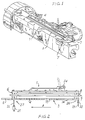
- FIG. 1 is a perspective view of the cigarette packing machine exit ramp of the present invention;
- FIG. 2 is a side elevational view of the exit ramp of the present invention;
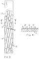
- FIG. 3 is a plan view of the preferred embodiment of the heater plate of the present invention;
- FIG. 4 is a vertical cross-sectional view of the preferred embodiment of heater plate of the present invention, taken along line 4-4 of FIG. 3;
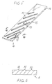
- FIG. 5 is an exit end, side perspective view of an alternate embodiment of the heater plate of the present invention;
- FIG. 6 is a vertical cross-sectional view of an alternate embodiment of the heater plate of the present invention, taken along line 6-6 of FIG. 5;
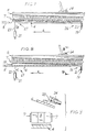
- FIG. 7 is a side elevational view of the exit ramp with the heater plate of the present invention raised at one end and pivoted at the other;
- FIG. 8 is a side elevational view of the exit ramp after the heater plate has been raised and retracted; and
- FIG. 9 is a vertical cross-sectional view of the exit ramp of the present invention taken along line 9-9 of FIG. 8.
-
- A sealed cigarette pack is formed by using a cigarette packer and dry adhesives, such as described in co-pending EP-A-0 514 203.
- The cigarette packer wraps a bundle of cigarettes first with a foil liner and then with a label having a pre-applied dry adhesive. The cigarette packer then forms seals, first at the pack bottom using a heat-applying processing turret and then at the pack sides using a heat-applying portion of an exit ramp.
- In one aspect of the present invention, the heated portion of the exit ramp bottom plate (the heater plate) comprises ridges that are formed on its surface at a diagonal to the longitudinal direction of the plate. These raised ridges function as pressure points to concentrate the heat from the heater plate on reduced areas of the cigarette pack sideseam that contact the ridges.
- In another aspect of the present invention, when the cigarette packing machine is shut off, the heater plate is raised and then returned to its original position. In one embodiment, the heater plate is raised at one end while being pivoted at the other end, and in another embodiment the heater plate is raised at both ends. The raising of the heater plate pushes the cigarette packs being conveyed along the exit apparatus upward so that the subsequent retraction of the heater plate leaves the cigarette packs held by the tension of the conveyor belts in a raised position. As a result, a gap is created such that the packs are separated from and are not heated by the heater plate when the packing machine is not in use.
- FIG. 1 shows a known wet-glue cigarette packer exit ramp apparatus 1 that has been modified in accordance with the present invention. Cigarette packs enter onto the exit ramp after having been wrapped in labels by the processing turrets. These labels, as disclosed in EP-A-0 514 203, preferably have a heat-activated dry adhesive pre-applied at edges corresponding to the sideseam of the cigarette pack and the folded over bottom of the cigarette pack, such that the labels are sealed around each pack by application of heat.
- As illustrated in FIG. 2, the exit ramp apparatus 1 of the present invention comprises a
bottom plate apparatus 3 comprising aheater plate 4 and acooling plate 5, atop pressure plate 6 and conveyingmeans 7. The conveying means can be any means for transporting the cigarette packs along thebottom plate 3, such as an inclined vibrating bottom plate or a pocket chain, but preferably comprisesside conveyor belts 7. Each cigarette pack enters onto the exit ramp 1, sideways, resting on the unsealed label sideseam. Each pack is conveyed longitudinally along thebottom plate 3 fromentrance end 26 to exitend 27 byconveyor belts 7 that impinge upon each pack at its top and bottom. Any number ofconveyor belts 7 may be used in order to effect thelongitudinal entrance 26 to exit 27 motion. - As the
packs 8 are transported along the exit ramp by theconveyor belts 7 in the direction indicated by reference arrow A in FIG. 2, thetop pressure plate 6 applies intermittent downward pressure by patting down onto the upward-facing sides of the cigarette packs so that the opposite sides of the packs are contacted with thebottom plate 3. In this way, the downward-facing side of each cigarette pack contacts thebottom plate 3, both at theheater plate portion 4 and at thecooling plate portion 5. The sideseam adhesive is thus both activated and set uniformly. - The
heater plate 4 of thebottom plate apparatus 3 comprises raised contact surfaces 10 that are formed on its otherwise flat surface. Thisnovel heater plate 4 is shown in more detail in FIGS. 3-6. As the packs are moved along theheater plate 4, the packs contact the plate only at the raised positions of the bottom plate. These raised contact surfaces 10 serve as pressure points to concentrate the heat from theheater 4 onto the label sideseam. - Because the heat from the
heater plate 4 is transferred to the cigarette packs over a smaller, more concentrated, area by using the raised contact surfaces 10, the sideseam seal can be activated at lower temperatures than previously required with a completely flat heater plate surface. One result of concentrating the heat on these contact surfaces is that less heat from the heater plate is required to activate the seal on the cigarette packs. - In the preferred embodiment of this invention, shown in FIG. 3, elongated
ridges 10 in theheater plate 4 are formed parallel to each other and at a diagonal to the longitudinal direction of the plate. These diagonalelongated ridges 10 effectively serve to move the raised pressure points across the sides of the cigarette packs as the packs are moved in the longitudinal direction along theheater plate 4. In this way, concentrated heat is applied along the seal, progressing from one end of the seal to the other. - In an alternative embodiment of this invention, elongated ridges may be formed on the bottom plate such that the ridged portions of the bottom plate form intersecting crossing patterns, such as an "X" (not shown). In another alternative embodiment, a series of shortened ridges is formed so that the ridges are parallel to each other in the longitudinal direction of the heater plate but are offset slightly from one another such that the row of short ridges is generally at a diagonal to the longitudinal direction of the heater plate (not shown). Other alternative ridging patterns also can be formed such that the raised contact portions are in a generally angular pattern such that the raised pressure points move across the sides of the packs as the packs progress along the bottom plate.
- The raised contact surfaces may be manufactured using any known process. Die-casting can be used to form elongated
narrow ridges 10 as part of the surface of theheater plate 4 at the time of its manufacture. Rather than casting a flat bottom plate surface, a ridged bottom plate surface is cast. Such ridges are shown in FIGS. 5 and 6. - The preferred method of creating the narrow raised contact surfaces 10 is by beveling
elongated grooves 12 into the flat surface of theheater plate 4. Thesegrooves 12 are shown in cross-section in FIG. 4. After beveling, the remaining raisedportions 10 function as the pressure points that concentrate the bottom plate heat onto the cigarette pack sideseam as the pack moves along theheater plate 4. This beveling method may be used to modify the existing bottom plates of known exit ramps. - Alternatively, the
beveled heater plate 4 may be further modified by being inlayed with a heat insulating material between the ridges 10 (not shown). After bevelinggrooves 12 into the flat heater plate, a heat insulating material, such as a high temperature plastic, is poured into the grooves and allowed to dry. Or, pre-formed ceramic inserts may be placed betweenridges 10. The heat insulating material helps to shield the cigarette packs 8 resting on the bottomheater plate ridges 10 from the convective heat of the bottom plate, thus preventing convective overheating of the cigarette packs. - In a preferred embodiment of this invention, the
contact ridges 10 are formed by bevelinggrooves 12 approximately 750mm (30/1000") deep, approximately 15mm (5/8") wide and approximately 3mm (1/8") apart. In effect, this creates a profile with contact points each 750 mm (30/1000") high and 3mm (1/8") wide, and spaced 15mm (5/8") apart. Alternatively, the raisedcontact ridges 10 may be formed by bevelinggrooves 12 with different, more suitable depth, width and spacing. - Also in the preferred embodiment, the contact surfaces 10 preferably do not extend along the entire length of the
heater plate 4, but rather extend along the portion of the length closest to theexit end 27, preferably the last 80% of the length of theheater plate 4. Thefirst portion 14 of the heater plate, closest to entrance end 26, is flat, without any grooves or raised portions, as shown in FIGS. 3 and 5. Thus, when the cigarette packs enter onto the exit ramp at theentrance end 26 and move along the exit ramp toward theexit end 27, the downward-facing sides of the cigarette packs, having the label seam to be sealed, contact the entire width of theheater plate 4 for theinitial portion 14 of the plate's length. Then, for thefinal portion 15 of the plate's length, the cigarette packs contact the raised contact surfaces 10. The effect of this flat/ridged construction of theheater plate 4 is that a slight partial seal is formed in each cigarette pack sideseam by the initial flat portion of theheater plate 4. This partial seal helps to diminish the possibility of skewed or uneven seals in the progressive sealing process of the present invention. - After the cigarette packs are conveyed past the heated portion of the exit ramp, they are conveyed to the cooling portion of the exit ramp. The cooling portion may be a
separate plate 5, as shown in FIGS. 7 and 8, or may be a continuous portion of the exit rampbottom plate 3 downstream of theheater portion 4 of the exit ramp bottom plate. The cooling portion preferably is a combination having two sequential components. The first part preferably is a cooled section at the exit end of theheated plate 4 and the second part preferably is aseparate cooling plate 5 downstream of theheated plate 4. Theseparate cooling plate 5 may be a separate metal plate generally at ambient temperature, i.e. without forced cooling. To avoid heating due to proximity withheater plate 4, thecooling plate 5 preferably is cooled by external means, such as by passing cool air or liquid under it, or by some other cooling method. The cooling portion of the exit ramp may be flat or may be contoured in one of the ridging patterns discussed above. - In another aspect of the present invention, when the packing machine is shut off, the
heater plate 4 is raised and then is returned to its original position. In a first preferred embodiment, theheater plate 4 is raised at one end while being pivoted at the other end. In a second embodiment, theheater plate 4 is raised at both ends. Raising and retraction of the heater plate in the preferred embodiment are illustrated in FIGS. 7 and 8 respectively. Raising theheater plate 4 pushes the cigarette packs 8 that are being conveyed along the exit apparatus upward so that the subsequent retraction of theheater plate 4 to its original position leaves thepacks 8 held in a raised position by the tension of theconveyor belts 7. As a result, agap 18 is created between theheater plate 4 and the cigarette packs 8 such that thepacks 8 are spatially separated from and are generally not heated by theheater plate 4 when the packing machine is not in use. The spatial gap between thepacks 8 and theheater plate 4 reduces the heat transferred to thepacks 8, thus protecting thepacks 8 from over-heating by theheater plate 4 and the resulting heat degradation. - In a preferred embodiment, cool air is blown through the
gap 18 between thepacks 8 and the heater plate 4.to further cool thepacks 8. Whereas creating thegap 18 prevents conductive overheating of the packs contacting the heater plate, blowing cool air through thegap 18 prevents convective overheating of thepacks 8 by cooling the heat emanating from theheater plate 4. - The present invention also comprises a
top pressure plate 6 that pats down on the upward-facing sides of the cigarette packs 8 so that the opposite sides of the cigarette packs contact thebottom plate 3. In a first embodiment of the top pressure plate, the top pressure plate provides fixed pressure intermittently upon thepacks 8 so that they contact the bottom plate surface. In another embodiment, thetop pressure plate 6 is spring-loaded so that thepacks 8 are not crushed by the downward pressure of thetop pressure plate 6. In still another embodiment, the top pressure plate is self-leveling so that pressure by thetop plate 6 is applied to the cigarette packs 8 uniformly, causing the entire downward-facing side of each cigarette pack to contact thebottom plate 3. Self-leveling may be accomplished by a ball-and-socket mount, by a swivel mount or by some other suitable mounting means. In a further preferred embodiment, the spring-loadedtop pressure plate 6 is also retractable, as shown in FIG. 9. It is preferable thattop plate 6 be retracted prior to the raising of thebottom plate 4 so that cigarette packs 8 on the exit ramp are not crushed or deformed by opposing action of the two plates. - Any switching apparatus (not shown in the figures) may be used to turn the packing machine on or off -- such as any of the known electrical and mechanical switches.
- Any apparatus may be used for raising, retracting and pivoting the
heater plate 4. In the first, preferred embodiment, at the pivot end, along bolt 19 and ahigh tension spring 20 may be used to create a pivot axis. At the raised end, a doubleacting air cylinder 21 and a connectingrod 22 may be used to raise and retract that end of theheater plate 4. In this preferred embodiment, the exit rampbottom plate 4 is raised at the exit end 27 of the exit ramp and is pivoted at theentrance end 26 of the exit ramp. In the second embodiment (not shown), raising of theheater plate 4 is done at both theentrance end 26 and the exit end 27 of the exitramp heater plate 4, preferably by the above apparatus. - Likewise, any apparatus may be used for raising and retracting the
top pressure plate 6. In one embodiment, ashaft 23 connected to thetop pressure plate 6 may be equipped with anair cylinder assembly 24 to retract the plate. - In the preferred embodiment of this invention, when the packing machine is switched off, the top pressure
plate air cylinder 24 is activated to retract thetop pressure plate 6, and then the bottomplate air cylinder 21 is activated to raise and lower the exit end 27 of theheater plate 4 in the directions indicated by reference arrows B and C in FIGS. 7 and 8, respectively. Theentrance end 26 of theheater plate 4 remains pivotally mounted such that it pivots aboutspring 20 when theexit end 27 is raised and lowered. In the second embodiment (not shown), after thetop pressure plate 6 is retracted, a bottom plate air cylinder on each end of the heater plate is activated to raise and lower the entire heater plate. Later, when the packing machine is restarted, the top pressureplate air cylinder 24 is reactivated so that thetop pressure plate 6 moves back to its functional position and in the process pushes the suspended cigarette packs 8 back down into contact with thebottom plate 4. - The
air cylinders - Further, in the preferred embodiment, the bottom
plate air cylinder 21 raises the exit end 27 of the exit ramp'sheater plate 4 by a preferred distance of at least one-half inch. In the second embodiment, both ends of the heater plate are raised by a preferred distance of at least one-half inch. - The exit apparatus of the invention finds particular application at the exit end of a turret type cigarette packer such as a GDX-1.
Claims (20)
- A cigarette packing machine exit apparatus (1) for activating pre-applied adhesive on sideseams of cigarette packs, comprising:a heater plate (4); anda conveyor (7) for transporting cigarette packs along an exit apparatus path comprising the heater plate so that the sideseams of the cigarette packs contact at least a portion of the top surface of the heater plate, in which the top surface of the heater plate comprises a plurality of contact surfaces (10) characterised in that the heater plate (4) is pivotally mounted to be movable between an operating position and a pivoted position and in that the apparatus further comprises:a pivot axis to which the heater plate is pivotally mounted; andpivot motion means (21,22) for moving the heater plate about the pivot axis.
- Apparatus (1) according to claim 1 wherein the conveyor comprises a plurality of conveyor belts (7).
- Apparatus (1) according to claim 1 or 2 wherein the conveyor comprises two opposing conveyor belts (7) each running the entire longitudinal length of the exit apparatus path.
- Apparatus (1) according to any preceding claim wherein the exit apparatus path further comprises:a cooling plate (5) situated such that the entrance end of the cooling plate (5) is aligned with the exit end of the heater plate (4) such that the conveyor (7) can transport cigarette packs from the exit end of the heater plate towards the entrance end of the cooling plate.
- Apparatus (1) according to claim 4 wherein the pivot axis is adjacent the entrance end of the heater plate.
- Apparatus (1) according to any preceding claim further comprising a switch for switching the packing machine between operating and off conditions, wherein the pivot motion means (21,22) causes the heater plate (4) to be pivoted upward when the switch is activated to switch the packing machine to the off condition.
- Apparatus (1) according to claim 6 wherein the pivot motion means (21,22) causes heater plate (4) to return to its operating position after the pivot motion means or the lifting means causes the heater plate to be pivoted upwards.
- Apparatus (1) according to any preceding claim wherein the conveyor comprises a plurality of opposing conveyor belts (7) mounted on opposite transverse sides of the heater plate (4) and mounted such that they support the packs spatially separate from the heater plate after the pivot motion means (21,22) causes the heater plate to return to its operating position.
- Apparatus (1) according to any preceding claim wherein the contact surfaces comprise contact ridges (10) parallel to each other and oriented diagonally with respect to the exit apparatus path.
- Apparatus according to claim 9 wherein the contact ridges intersect with one another to create a plurality of crossing patterns.
- Apparatus (1) according to claim 9 or 10 wherein the contact ridges (10) extend along less than the entire length of the heater plate (4).
- Apparatus according to any of claims 9 to 11 further comprising heat insulating means between the contact ridges (10) to insulate the packs from the top surface of the heater plate.
- Apparatus according to any preceding claim wherein the contact surfaces (10) comprise a plurality of shortened contact ridges parallel to each other and to the exit apparatus path, the plurality being generally oriented diagonally with respect to the exit apparatus path.
- Apparatus (1) according to any preceding claim further comprising a top pressure plate (6) mounted to provide pressure to the cigarette packs opposing the top surface of the heater plate (4).
- Apparatus (1) according to claim 14 wherein the top pressure plate (6) is spring mounted.
- Apparatus (1) according to claim 14 wherein the top pressure plate (6) is swivel mounted to be self-levelling.
- Apparatus (1) according to any of claims 14 to 16 wherein the top pressure plate (6) is mounted to be movable between an operating position and a retracted position and further comprising a retractor (24) for moving top pressure plate between the operating position and the retracted position; anda switch for switching the packing machine between operating and off conditions, wherein the retractor causes the top pressure plate to retract when the switch is activated to switch the packing machine to the off condition.
- Apparatus for manufacturing cigarette packs comprising packaging stock having a pre-applied dry heat adhesive coated on a portion of its inside surface, the apparatus comprising:a bundler for forming a bundle of stock-wrapped cigarettes, each bundle being wrapped such that the inside surface of the packaging stock is adjacent the cigarettes and each of the bundles includes a side seam comprising pre-applied dry heat adhesive coated on a portion of the inside surface of the packaging stock;exit apparatus according to any of claims 1 or 17 for activating the pre-applied dry heat adhesive of the sideseams of the bundles by contacting the sideseams with the plurality of contact surfaces (10) of the heater plate (4), the exit apparatus including a cooling plate (5) according to claim 4 for setting the pre-applied dry heat-activated adhesive of the sideseams of the stock-wrapped bundles by contacting each of the sideseams with the cooling plate (5), the cooling plate (5) being downstream of the heater plate (4).
- Apparatus according to claim 18 comprising:a feeder for transporting the packaging stock along a feed path; andan assembler for gathering a plurality of cigarettes that are to be included in each cigarette pack,the bundler being downstream of the feeder and the assembler.
- Apparatus according to claim 18 or 19 in the form of a turret-type cigarette packing machine wherein the heater plate (4) is situated in proximity to the activation turret such that the heater plate applies heat to the sideseam of each stock-wrapped bundle when it is on the exit apparatus (1).
Applications Claiming Priority (2)
| Application Number | Priority Date | Filing Date | Title |
|---|---|---|---|
| US08/081,974 US5447014A (en) | 1991-05-15 | 1993-06-23 | Cigarette packing machine exit apparatus |
| US81974 | 2002-02-21 |
Publications (2)
| Publication Number | Publication Date |
|---|---|
| EP0630819A1 EP0630819A1 (en) | 1994-12-28 |
| EP0630819B1 true EP0630819B1 (en) | 2000-05-03 |
Family
ID=22167593
Family Applications (1)
| Application Number | Title | Priority Date | Filing Date |
|---|---|---|---|
| EP94304579A Expired - Lifetime EP0630819B1 (en) | 1993-06-23 | 1994-06-23 | Cigarette packing machine exit apparatus |
Country Status (5)
| Country | Link |
|---|---|
| US (1) | US5447014A (en) |
| EP (1) | EP0630819B1 (en) |
| AT (1) | ATE192394T1 (en) |
| CZ (1) | CZ150894A3 (en) |
| DE (1) | DE69424226D1 (en) |
Families Citing this family (10)
| Publication number | Priority date | Publication date | Assignee | Title |
|---|---|---|---|---|
| DE19535649A1 (en) * | 1995-09-26 | 1997-03-27 | Focke & Co | Method and device for producing packaging with an outer wrapping made of paper or the like |
| AU2002310184B2 (en) * | 2001-06-01 | 2006-11-23 | Colgate-Palmolive Company | Soap bar wrapper |
| ITBO20050167A1 (en) * | 2005-03-17 | 2005-06-16 | Gd Spa | METHOD AND DEVICE FOR PACKAGING PACKAGES FOR SMOKE ITEMS |
| US9902517B2 (en) * | 2013-11-01 | 2018-02-27 | Frito-Lay North America, Inc. | Apparatus and method for a structurally resilient package |
| US9840346B2 (en) | 2013-11-01 | 2017-12-12 | Frito-Lay North America, Inc. | Method and apparatus for making a structurally resilient package |
| USD873317S1 (en) * | 2018-06-11 | 2020-01-21 | Baron Buehring | Side panel for high capacity dispensing unit |
| USD869527S1 (en) * | 2018-06-11 | 2019-12-10 | Baron Buehring | Side panel for high capacity dispensing unit |
| USD868860S1 (en) * | 2018-06-11 | 2019-12-03 | Baron Buehring | Side panel for high capacity dispensing unit |
| USD868858S1 (en) * | 2018-06-11 | 2019-12-03 | Baron Buehring | Side panel for high capacity dispensing unit |
| USD868859S1 (en) * | 2018-06-11 | 2019-12-03 | Baron Buehring | Side panel for high capacity dispensing unit |
Family Cites Families (10)
| Publication number | Priority date | Publication date | Assignee | Title |
|---|---|---|---|---|
| US2638724A (en) * | 1945-12-19 | 1953-05-19 | Molins Machine Co Ltd | Method of and apparatus for sealing wrappers |
| US2480501A (en) * | 1946-09-25 | 1949-08-30 | Reynolds Metals Co | Means for producing cigarette packages |
| US2697474A (en) * | 1951-07-31 | 1954-12-21 | American Mach & Foundry | Hot seal cooling mechanism |
| US3010267A (en) * | 1959-05-25 | 1961-11-28 | Chicago Carton Co | Carton sealing apparatus |
| US3140971A (en) * | 1962-03-14 | 1964-07-14 | Package Machinery Co | Heat sealing channel |
| US3599394A (en) * | 1969-08-26 | 1971-08-17 | Triangle Package Machinery Co | Automatic wrapping machines |
| DE2219540A1 (en) * | 1972-04-21 | 1973-10-31 | Niepmann & Co Maschf Fr | METHOD AND DEVICE FOR MANUFACTURING PACKS OF CIGARETTES |
| IT982254B (en) * | 1973-03-05 | 1974-10-21 | Gd Spa | EQUIPMENT FOR THE OUTPUT OF PRODUCTS FROM A Wrapping and packaging line of said products, particularly packs of cigarettes and similar |
| US4362593A (en) * | 1980-11-17 | 1982-12-07 | Nordson Corporation | Walking-beam band sealer |
| CA2068568A1 (en) * | 1991-05-15 | 1992-11-16 | John M. Adams | Cigarette packaging machine and apparatus |
-
1993
- 1993-06-23 US US08/081,974 patent/US5447014A/en not_active Expired - Fee Related
-
1994
- 1994-06-20 CZ CZ941508A patent/CZ150894A3/en unknown
- 1994-06-23 AT AT94304579T patent/ATE192394T1/en not_active IP Right Cessation
- 1994-06-23 EP EP94304579A patent/EP0630819B1/en not_active Expired - Lifetime
- 1994-06-23 DE DE69424226T patent/DE69424226D1/en not_active Expired - Lifetime
Also Published As
| Publication number | Publication date |
|---|---|
| US5447014A (en) | 1995-09-05 |
| ATE192394T1 (en) | 2000-05-15 |
| CZ150894A3 (en) | 1995-12-13 |
| EP0630819A1 (en) | 1994-12-28 |
| DE69424226D1 (en) | 2000-06-08 |
Similar Documents
| Publication | Publication Date | Title |
|---|---|---|
| EP0630819B1 (en) | Cigarette packing machine exit apparatus | |
| KR100233230B1 (en) | Method and apparatus for manufacturing cigarette packs | |
| KR100454350B1 (en) | Packing machine for multi-packs | |
| US4475653A (en) | Package and process of forming same | |
| FI89149C (en) | Foerfarande och anordning Foer emballering av rullar, i synnerhet pappersrullar, med foerpackningsomslag | |
| CA1272632A (en) | Carrying handle for a can carton | |
| GB2139175A (en) | A machine for packing continuously moving articles with a strip of heat-shrinkable material | |
| DE68921225T2 (en) | DEVICE FOR APPLYING PACKING SLEEVES. | |
| EP0351553A1 (en) | Device for sealing the overlapped end flaps of a thermoplastic material wrapper for packages, particularly for packages of cigarettes | |
| US2638724A (en) | Method of and apparatus for sealing wrappers | |
| EP0394579A1 (en) | Dual station wrapping machine | |
| EP0378787B1 (en) | Apparatus for closing a package around an article to be packaged | |
| EP0161542B1 (en) | Reciprocating folder for packaging machines | |
| KR950000538A (en) | Packing material removal device | |
| US4792246A (en) | Apparatus for raised printing | |
| US4905446A (en) | Apparatus for wrapping articles | |
| US5871431A (en) | Plant for manufacturing cardboard containers and the manufacturing method for said containers | |
| KR20000069726A (en) | Method and device for packaging compressible materials | |
| EP0058652A1 (en) | A method and an apparatus for packaging ice cream articles in individual wrappings | |
| NL8303012A (en) | METHOD AND APPARATUS FOR PACKAGING SPATIAL PRODUCTS. | |
| US4671045A (en) | Method and assembly for sealing articles | |
| US6505458B1 (en) | Method and machine for packing a group of products | |
| NL8201936A (en) | METHOD AND APPARATUS FOR PACKING GOODS | |
| JP2670594B2 (en) | Heat sealing equipment for packaging line | |
| EP0119032A1 (en) | Packaging machine |
Legal Events
| Date | Code | Title | Description |
|---|---|---|---|
| PUAI | Public reference made under article 153(3) epc to a published international application that has entered the european phase |
Free format text: ORIGINAL CODE: 0009012 |
|
| AK | Designated contracting states |
Kind code of ref document: A1 Designated state(s): AT BE CH DE DK ES FR GB GR IE IT LI LU MC NL PT SE |
|
| RAX | Requested extension states of the european patent have changed |
Free format text: SI PAYMENT 940721 |
|
| 17P | Request for examination filed |
Effective date: 19950502 |
|
| 17Q | First examination report despatched |
Effective date: 19960802 |
|
| GRAG | Despatch of communication of intention to grant |
Free format text: ORIGINAL CODE: EPIDOS AGRA |
|
| GRAG | Despatch of communication of intention to grant |
Free format text: ORIGINAL CODE: EPIDOS AGRA |
|
| GRAH | Despatch of communication of intention to grant a patent |
Free format text: ORIGINAL CODE: EPIDOS IGRA |
|
| GRAH | Despatch of communication of intention to grant a patent |
Free format text: ORIGINAL CODE: EPIDOS IGRA |
|
| GRAA | (expected) grant |
Free format text: ORIGINAL CODE: 0009210 |
|
| AK | Designated contracting states |
Kind code of ref document: B1 Designated state(s): AT BE CH DE DK ES FR GB GR IE IT LI LU MC NL PT SE |
|
| AX | Request for extension of the european patent |
Free format text: SI PAYMENT 19940721 |
|
| PG25 | Lapsed in a contracting state [announced via postgrant information from national office to epo] |
Ref country code: NL Free format text: LAPSE BECAUSE OF FAILURE TO SUBMIT A TRANSLATION OF THE DESCRIPTION OR TO PAY THE FEE WITHIN THE PRESCRIBED TIME-LIMIT Effective date: 20000503 Ref country code: LI Free format text: LAPSE BECAUSE OF FAILURE TO SUBMIT A TRANSLATION OF THE DESCRIPTION OR TO PAY THE FEE WITHIN THE PRESCRIBED TIME-LIMIT Effective date: 20000503 Ref country code: IT Free format text: LAPSE BECAUSE OF FAILURE TO SUBMIT A TRANSLATION OF THE DESCRIPTION OR TO PAY THE FEE WITHIN THE PRESCRIBED TIME-LIMIT;WARNING: LAPSES OF ITALIAN PATENTS WITH EFFECTIVE DATE BEFORE 2007 MAY HAVE OCCURRED AT ANY TIME BEFORE 2007. THE CORRECT EFFECTIVE DATE MAY BE DIFFERENT FROM THE ONE RECORDED. Effective date: 20000503 Ref country code: GR Free format text: LAPSE BECAUSE OF NON-PAYMENT OF DUE FEES Effective date: 20000503 Ref country code: FR Free format text: LAPSE BECAUSE OF FAILURE TO SUBMIT A TRANSLATION OF THE DESCRIPTION OR TO PAY THE FEE WITHIN THE PRESCRIBED TIME-LIMIT Effective date: 20000503 Ref country code: CH Free format text: LAPSE BECAUSE OF FAILURE TO SUBMIT A TRANSLATION OF THE DESCRIPTION OR TO PAY THE FEE WITHIN THE PRESCRIBED TIME-LIMIT Effective date: 20000503 Ref country code: BE Free format text: LAPSE BECAUSE OF FAILURE TO SUBMIT A TRANSLATION OF THE DESCRIPTION OR TO PAY THE FEE WITHIN THE PRESCRIBED TIME-LIMIT Effective date: 20000503 Ref country code: AT Free format text: LAPSE BECAUSE OF FAILURE TO SUBMIT A TRANSLATION OF THE DESCRIPTION OR TO PAY THE FEE WITHIN THE PRESCRIBED TIME-LIMIT Effective date: 20000503 |
|
| REF | Corresponds to: |
Ref document number: 192394 Country of ref document: AT Date of ref document: 20000515 Kind code of ref document: T |
|
| PGFP | Annual fee paid to national office [announced via postgrant information from national office to epo] |
Ref country code: DK Payment date: 20000512 Year of fee payment: 7 |
|
| REG | Reference to a national code |
Ref country code: CH Ref legal event code: EP |
|
| PGFP | Annual fee paid to national office [announced via postgrant information from national office to epo] |
Ref country code: IE Payment date: 20000517 Year of fee payment: 7 Ref country code: AT Payment date: 20000517 Year of fee payment: 7 |
|
| PGFP | Annual fee paid to national office [announced via postgrant information from national office to epo] |
Ref country code: FR Payment date: 20000518 Year of fee payment: 7 |
|
| PGFP | Annual fee paid to national office [announced via postgrant information from national office to epo] |
Ref country code: SE Payment date: 20000519 Year of fee payment: 7 Ref country code: MC Payment date: 20000519 Year of fee payment: 7 |
|
| PGFP | Annual fee paid to national office [announced via postgrant information from national office to epo] |
Ref country code: CH Payment date: 20000522 Year of fee payment: 7 |
|
| PGFP | Annual fee paid to national office [announced via postgrant information from national office to epo] |
Ref country code: GB Payment date: 20000523 Year of fee payment: 7 |
|
| PGFP | Annual fee paid to national office [announced via postgrant information from national office to epo] |
Ref country code: NL Payment date: 20000524 Year of fee payment: 7 Ref country code: DE Payment date: 20000524 Year of fee payment: 7 |
|
| REG | Reference to a national code |
Ref country code: IE Ref legal event code: FG4D |
|
| PGFP | Annual fee paid to national office [announced via postgrant information from national office to epo] |
Ref country code: ES Payment date: 20000608 Year of fee payment: 7 |
|
| REF | Corresponds to: |
Ref document number: 69424226 Country of ref document: DE Date of ref document: 20000608 |
|
| PGFP | Annual fee paid to national office [announced via postgrant information from national office to epo] |
Ref country code: BE Payment date: 20000615 Year of fee payment: 7 |
|
| PGFP | Annual fee paid to national office [announced via postgrant information from national office to epo] |
Ref country code: LU Payment date: 20000622 Year of fee payment: 7 |
|
| PG25 | Lapsed in a contracting state [announced via postgrant information from national office to epo] |
Ref country code: SE Free format text: LAPSE BECAUSE OF FAILURE TO SUBMIT A TRANSLATION OF THE DESCRIPTION OR TO PAY THE FEE WITHIN THE PRESCRIBED TIME-LIMIT Effective date: 20000803 Ref country code: PT Free format text: LAPSE BECAUSE OF FAILURE TO SUBMIT A TRANSLATION OF THE DESCRIPTION OR TO PAY THE FEE WITHIN THE PRESCRIBED TIME-LIMIT Effective date: 20000803 Ref country code: DK Free format text: LAPSE BECAUSE OF FAILURE TO SUBMIT A TRANSLATION OF THE DESCRIPTION OR TO PAY THE FEE WITHIN THE PRESCRIBED TIME-LIMIT Effective date: 20000803 |
|
| PG25 | Lapsed in a contracting state [announced via postgrant information from national office to epo] |
Ref country code: DE Free format text: LAPSE BECAUSE OF FAILURE TO SUBMIT A TRANSLATION OF THE DESCRIPTION OR TO PAY THE FEE WITHIN THE PRESCRIBED TIME-LIMIT Effective date: 20000804 |
|
| EN | Fr: translation not filed | ||
| NLV1 | Nl: lapsed or annulled due to failure to fulfill the requirements of art. 29p and 29m of the patents act | ||
| REG | Reference to a national code |
Ref country code: CH Ref legal event code: PL |
|
| PG25 | Lapsed in a contracting state [announced via postgrant information from national office to epo] |
Ref country code: ES Free format text: LAPSE BECAUSE OF FAILURE TO SUBMIT A TRANSLATION OF THE DESCRIPTION OR TO PAY THE FEE WITHIN THE PRESCRIBED TIME-LIMIT Effective date: 20001120 |
|
| PLBE | No opposition filed within time limit |
Free format text: ORIGINAL CODE: 0009261 |
|
| STAA | Information on the status of an ep patent application or granted ep patent |
Free format text: STATUS: NO OPPOSITION FILED WITHIN TIME LIMIT |
|
| 26N | No opposition filed | ||
| PG25 | Lapsed in a contracting state [announced via postgrant information from national office to epo] |
Ref country code: LU Free format text: LAPSE BECAUSE OF NON-PAYMENT OF DUE FEES Effective date: 20010623 Ref country code: GB Free format text: LAPSE BECAUSE OF NON-PAYMENT OF DUE FEES Effective date: 20010623 |
|
| PG25 | Lapsed in a contracting state [announced via postgrant information from national office to epo] |
Ref country code: IE Free format text: LAPSE BECAUSE OF NON-PAYMENT OF DUE FEES Effective date: 20010625 |
|
| PG25 | Lapsed in a contracting state [announced via postgrant information from national office to epo] |
Ref country code: MC Free format text: LAPSE BECAUSE OF NON-PAYMENT OF DUE FEES Effective date: 20010630 |
|
| GBPC | Gb: european patent ceased through non-payment of renewal fee |
Effective date: 20010623 |