EP0630489B1 - Camera - Google Patents
Camera Download PDFInfo
- Publication number
- EP0630489B1 EP0630489B1 EP92906662A EP92906662A EP0630489B1 EP 0630489 B1 EP0630489 B1 EP 0630489B1 EP 92906662 A EP92906662 A EP 92906662A EP 92906662 A EP92906662 A EP 92906662A EP 0630489 B1 EP0630489 B1 EP 0630489B1
- Authority
- EP
- European Patent Office
- Prior art keywords
- camera
- beam path
- viewfinder
- video
- handle
- Prior art date
- Legal status (The legal status is an assumption and is not a legal conclusion. Google has not performed a legal analysis and makes no representation as to the accuracy of the status listed.)
- Expired - Lifetime
Links
Images

Classifications
-
- H—ELECTRICITY
- H04—ELECTRIC COMMUNICATION TECHNIQUE
- H04N—PICTORIAL COMMUNICATION, e.g. TELEVISION
- H04N5/00—Details of television systems
- H04N5/222—Studio circuitry; Studio devices; Studio equipment
- H04N5/2228—Video assist systems used in motion picture production, e.g. video cameras connected to viewfinders of motion picture cameras or related video signal processing
-
- G—PHYSICS
- G03—PHOTOGRAPHY; CINEMATOGRAPHY; ANALOGOUS TECHNIQUES USING WAVES OTHER THAN OPTICAL WAVES; ELECTROGRAPHY; HOLOGRAPHY
- G03B—APPARATUS OR ARRANGEMENTS FOR TAKING PHOTOGRAPHS OR FOR PROJECTING OR VIEWING THEM; APPARATUS OR ARRANGEMENTS EMPLOYING ANALOGOUS TECHNIQUES USING WAVES OTHER THAN OPTICAL WAVES; ACCESSORIES THEREFOR
- G03B17/00—Details of cameras or camera bodies; Accessories therefor
- G03B17/48—Details of cameras or camera bodies; Accessories therefor adapted for combination with other photographic or optical apparatus
-
- G—PHYSICS
- G03—PHOTOGRAPHY; CINEMATOGRAPHY; ANALOGOUS TECHNIQUES USING WAVES OTHER THAN OPTICAL WAVES; ELECTROGRAPHY; HOLOGRAPHY
- G03B—APPARATUS OR ARRANGEMENTS FOR TAKING PHOTOGRAPHS OR FOR PROJECTING OR VIEWING THEM; APPARATUS OR ARRANGEMENTS EMPLOYING ANALOGOUS TECHNIQUES USING WAVES OTHER THAN OPTICAL WAVES; ACCESSORIES THEREFOR
- G03B19/00—Cameras
- G03B19/18—Motion-picture cameras
- G03B19/20—Reflex cameras
-
- H—ELECTRICITY
- H04—ELECTRIC COMMUNICATION TECHNIQUE
- H04N—PICTORIAL COMMUNICATION, e.g. TELEVISION
- H04N23/00—Cameras or camera modules comprising electronic image sensors; Control thereof
-
- H—ELECTRICITY
- H04—ELECTRIC COMMUNICATION TECHNIQUE
- H04N—PICTORIAL COMMUNICATION, e.g. TELEVISION
- H04N23/00—Cameras or camera modules comprising electronic image sensors; Control thereof
- H04N23/50—Constructional details
Definitions
- the invention relates to a motion picture film recording camera according to the preamble of claim 1.
- a motion picture film recording camera with a film recording beam path is known, from which a viewfinder beam path is temporarily branched off by means of a periodically interrupting mirror. From this viewfinder beam path, a video beam path is branched off to a video recording camera by a beam splitter, so that film and television recordings can be made at the same time.
- This known camera has a bulky construction, since the viewfinder magnifier is arranged rigidly above the camera housing parallel to the lens and the video recording camera perpendicular to the lens axis.
- a compact camera construction with a handle and attachable film cassettes is not possible with such an arrangement.
- DE 22 00 690 C3 describes a motion picture seal reflex camera with viewing magnifying glass, in which the viewfinder beam path split off from the image-reflecting device by the mirror reflex device emerges from the camera housing in the center above the image-taking lens.
- the viewfinder exit from the camera housing is arranged on its front side and around the central axis of this viewfinder exit, the eyepiece view of the viewing magnifier, which is deflected backwards by means of at least one articulated magnifying glass arm and one eyepiece holder, can be pivoted between the right and left camera sides.
- the invention has for its object to design a compact, portable motion picture camera with slide-in cassettes in such a way that it permits a bilateral arrangement of the viewing device even when a video output is arranged.
- the solution according to the invention enables the viewing device (viewfinder magnifier) to be pivoted to either side of the camera lens, so that viewing the object on the right and left is possible without any problems, even if an additional one Video facility is provided.
- a partially transparent reflecting beam splitter is arranged in the viewfinder beam path, which is branched off from the film recording beam path in particular by an SLR device, and reflects a viewfinder beam component into a viewfinder exit on the front of the camera housing.
- an eyepiece insight of the viewing magnifier which is deflected backwards by means of a hinged magnifying arm and an eyepiece holder hinged to the eyepiece holder, can be pivoted between the right and left camera sides, and the video beam path let through by the beam splitter is fed through a rotary bearing of a camera handle to a video adapter arranged thereon.
- both the viewfinder exit and the exit of the video beam path are arranged at the front end of the camera due to this construction and the connection of the video adapter to the camera handle and the pivotable mounting of the camera handle enables the rear of the camera to be swiveled for one Slide-in cassette is easily accessible and that in the operating position of the handle a sufficient handle length is available to transport the motion picture film recording camera easily and conveniently by means of the handle.
- the swiveling of the eyepiece insight from the left camera side to the right enables a view from both sides and furthermore, with different camera inserts, middle positions of the eyepiece insight. Because of the arrangement of the video adapter, this view of the eyepiece can be guided past it in a pivoted position and then put into operation.
- the finder beam path which is periodically deflected, for example, by a mirrored orifice plate, is offset parallel to the front of the camera in order to be fed there to the beam splitter. This makes it possible to design the pivot bearing or the handle base for the handle in the region of the upper front edge of the film camera.
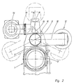
- the motion picture camera has a housing 1, on the front side 2 of which a taking lens 3 is arranged.
- the film recording beam path passing through the taking lens 3 is periodically interrupted by a rotating mirror diaphragm, which deflects a viewfinder beam path 4 upward out of this film recording beam path 18.
- This viewfinder beam path 4 is displaced to the front 2 of the motion picture camera by means of a rhomboid prism 17 and strikes a partially reflecting or partially transparent beam splitter 5.
- a beam component 6 is reflected by this beam splitter 5 to a viewfinder exit 7, which is arranged in the front side 2 of the camera housing 1.
- a magnifying arm 10 articulated at 9 is pivotably mounted in the region of more than 200 ° about the central axis 8, as shown in FIG.
- an eyepiece holder 11 is rotatably mounted, to which the eyepiece 12 of the viewfinder magnifier is attached.
- this construction enables a left-hand view and, due to the dash-dotted pivotability of the eyepiece view 12, enables the right and left-eyed viewing of the image generated by the taking lens 3.
- the eyepiece 12 can be used for a right-hand view, with a left- and right-eyed one also on the right side Insight into the eyepiece is possible.
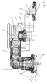
- a handle base 15 of the camera handle is formed in the top of the camera housing 1 on the front side 2, and a handle 14 of the camera handle is rotatably mounted in this handle base 15.
- the video beam path 13 is guided upwards by the beam splitter 5 through the handle base 15 of the camera handle and fed from a reflection prism 19 in the handle base 15 to a video adapter 16 which is mounted on the camera handle.
- the video beam path 13 is deflected by a prism 20, so that the video beam path 13 emerges from the video adapter 16 parallel to the taking lens 3.
- a video camera is connected to the video adapter 16 in a manner known per se, which is connected to a monitor, for example via a video cable, and thus permits the assistant to view the recorded image separately.
- the viewfinder beam path is guided such that image viewing on both sides and left-eyed and right-eyed is possible, the video beam path emerging at the front end of the camera in such a way that the camera can be carried by means of a handle on the camera handle , which can have a corresponding length.
- the handle 14 of the camera handle which is sufficient for easy handling because of its pivotability Can have length without hindering a cassette change, is rotatably mounted on a handle base 15 of the camera handle and combined with the video output, so that both parts can be pivoted to insert a slide-in cassette.
Landscapes
- Engineering & Computer Science (AREA)
- Multimedia (AREA)
- Signal Processing (AREA)
- Physics & Mathematics (AREA)
- General Physics & Mathematics (AREA)
- Viewfinders (AREA)
- Camera Bodies And Camera Details Or Accessories (AREA)
Abstract
Claims (3)
- Caméra cinématographique comportantun boîtier de caméra (1) pourvu d'un socle (15) formant organe de préhension et sur la face avant (2) duquel est disposé un objectif de prise de vues (3),un trajet de rayonnement (4) du viseur dévié à partir du trajet de rayonnement de prise de vues (18) au moyen d'un dispositif reflex à miroir,un dispositif réfléchissant (5), qui est disposé dans le trajet du rayonnement (4) du viseur et qui dévie le trajet de rayonnement du viseur de telle sorte qu'une composante (6) du rayonnement du viseur est réfléchie dans une sortie (7) du viseur sur la face avant (2) du boîtier (1) de la caméra,une branche (10) de dispositif de grossissement, articulée sur la sortie (7) du viseur,un porte-oculaire (11), articulé sur la branche (10) du dispositif de grossissement et auquel est relié un oculaire de visée (12) rabattu sur le côté arrière du boîtier (1) de la caméra, d'une lentille de visée, qui peut basculer autour de l'axe médian (8) de la sortie (7) du viseur, entre le côté droit et le côté gauche du boîtier (1) de la caméra,caractérisée en ce
que le dispositif réfléchissant (5), qui dévie le trajet de rayonnement du viseur, est agencé sous la forme d'un diviseur de rayonnement partiellement transparent, servant à dévier un trajet de rayonnement vidéo (13) à partir du trajet de rayonnement (4) du viseur, et que dans la face supérieure du boîtier (1) de la caméra et sur la face avant (2) est disposé un socle (15) formant organe de préhension d'une poignée (14) de la caméra, montée rotative dans ce socle, sur lequel est prévu un adaptateur vidéo (16), auquel le trajet de rayonnement vidéo (13), transmis par le diviseur de rayonnement (5), est envoyé à travers le socle (15) formant organe de préhension. - Caméra cinématographique selon la revendication 1, caractérisée en ce que lorsque la poignée (14) de la caméra est dans la position de fonctionnement, le trajet de rayonnement vidéo (13) sort de l'adaptateur vidéo (16) parallèlement à l'objectif (3).
- Caméra cinématographique selon la revendication 1 ou 2, caractérisée en ce qu'entre le trajet du rayonnement (4) du viseur, qui est dévié par le dispositif reflex à miroir à partir du trajet de rayonnement cinématographique (18), et le diviseur de rayonnement (5) est inséré un dispositif optique (17) à deux miroirs, notamment un prisme rhomboïdal qui décale le trajet du rayonnement (4) du viseur en direction de la face avant (2) du boîtier (1) de la caméra.
Priority Applications (1)
| Application Number | Priority Date | Filing Date | Title |
|---|---|---|---|
| AT92906662T ATE145994T1 (de) | 1992-03-10 | 1992-03-10 | Laufbild-filmaufnahmekamera |
Applications Claiming Priority (1)
| Application Number | Priority Date | Filing Date | Title |
|---|---|---|---|
| PCT/DE1992/000205 WO1993018433A1 (fr) | 1992-03-10 | 1992-03-10 | Camera |
Publications (2)
| Publication Number | Publication Date |
|---|---|
| EP0630489A1 EP0630489A1 (fr) | 1994-12-28 |
| EP0630489B1 true EP0630489B1 (fr) | 1996-12-04 |
Family
ID=37429247
Family Applications (1)
| Application Number | Title | Priority Date | Filing Date |
|---|---|---|---|
| EP92906662A Expired - Lifetime EP0630489B1 (fr) | 1992-03-10 | 1992-03-10 | Camera |
Country Status (4)
| Country | Link |
|---|---|
| US (1) | US5612755A (fr) |
| EP (1) | EP0630489B1 (fr) |
| DE (2) | DE4107577C1 (fr) |
| WO (1) | WO1993018433A1 (fr) |
Families Citing this family (4)
| Publication number | Priority date | Publication date | Assignee | Title |
|---|---|---|---|---|
| EP0830781A4 (fr) * | 1995-03-24 | 1999-04-07 | Lightstorm Technologies Inc | Viseur video |
| EP1111443A1 (fr) * | 1999-12-21 | 2001-06-27 | Peter Dipl.-Ing. Denz | Caméra muni d'un viseur électronique à oberver par un oculaire |
| US20040212996A1 (en) * | 2003-05-02 | 2004-10-28 | Friedrich Burckhardt | Ring lamp |
| WO2014134487A1 (fr) * | 2013-02-28 | 2014-09-04 | Canfield Scientific, Incorporated | Dispositifs de dermoscopie |
Family Cites Families (12)
| Publication number | Priority date | Publication date | Assignee | Title |
|---|---|---|---|---|
| US2698356A (en) * | 1951-10-17 | 1954-12-28 | Paul A Roos | Combined motion-picture and television camera |
| FR2029969A5 (fr) * | 1969-03-20 | 1970-10-23 | Schaefer Albert | |
| DE2200690C3 (de) * | 1972-01-07 | 1975-09-11 | Arnold & Richter Kg, 8000 Muenchen | Laufbild-Spiegelreflexkamera |
| US3913116A (en) * | 1972-01-07 | 1975-10-14 | Arnold & Richter Kg | Camera with adjustable viewfinder |
| GB2076177B (en) * | 1980-04-18 | 1983-10-12 | Samuelson Film Service Ltd | Auxiliary viewfinder system for motion picture cameras |
| EP0162311A3 (fr) * | 1984-04-25 | 1987-08-19 | Arnold & Richter Cine Technik Gmbh & Co. Betriebs Kg | Circuit de commande pour une caméra vidéo et procédé pour la commande d'une caméra vidéo |
| US4591254A (en) * | 1984-10-26 | 1986-05-27 | Bronislaw Sokolowski | Adaptor for T.V. camera |
| DE3615424A1 (de) * | 1986-05-07 | 1987-11-12 | Arnold & Richter Kg | Laufbild-filmaufnahmekamera |
| US4705374A (en) * | 1986-09-11 | 1987-11-10 | Clairmont Camera, Inc. | Tilting viewfinder and video door accessory for motion-picture camera |
| US5166718A (en) * | 1987-10-30 | 1992-11-24 | Canon Kabushiki Kaisha | Finder optical system |
| US5034822A (en) * | 1989-09-13 | 1991-07-23 | Stevens William M | Video camera adaptor for film cameras |
| DE9013698U1 (fr) * | 1990-10-01 | 1990-12-06 | Denz, Peter, 8000 Muenchen, De |
-
1991
- 1991-03-07 DE DE4107577A patent/DE4107577C1/de not_active Expired - Lifetime
-
1992
- 1992-03-10 WO PCT/DE1992/000205 patent/WO1993018433A1/fr active IP Right Grant
- 1992-03-10 EP EP92906662A patent/EP0630489B1/fr not_active Expired - Lifetime
- 1992-03-10 US US08/295,890 patent/US5612755A/en not_active Expired - Lifetime
- 1992-03-10 DE DE59207636T patent/DE59207636D1/de not_active Expired - Lifetime
Non-Patent Citations (1)
| Title |
|---|
| Bedienungsanleitung ARRIFLEX 16 SR II, Arnold & Richter Cine Technik, München 1984, Seiten 27-29 und 49-51 * |
Also Published As
| Publication number | Publication date |
|---|---|
| EP0630489A1 (fr) | 1994-12-28 |
| US5612755A (en) | 1997-03-18 |
| DE4107577C1 (fr) | 1992-09-03 |
| DE59207636D1 (de) | 1997-01-16 |
| WO1993018433A1 (fr) | 1993-09-16 |
Similar Documents
| Publication | Publication Date | Title |
|---|---|---|
| DE2418402C3 (de) | Endoskop mit veränderbarer Richtung des Blickfeldes | |
| DE19814731B4 (de) | Operationsmikroskop | |
| DE2415319B2 (de) | Kamera zur aufnahme des augenhintergrundes | |
| DE4013592C2 (fr) | ||
| DE3529026A1 (de) | Optisches system fuer ein endoskop | |
| DE4212924A1 (de) | Stereomikroskop | |
| EP0523261A1 (fr) | Appareil de projection et de rétroprojection de diapositives | |
| DE3933190C2 (fr) | ||
| DE2437498B1 (de) | Einäugige Spiegelreflex-Kassettenfilmkamera mit einem Varioobjektiv | |
| EP0085317A1 (fr) | Tube binoculaire universelle pour microscopes | |
| EP0630489B1 (fr) | Camera | |
| DE3211084C2 (de) | Optisches Mikroskop-System | |
| WO1991012550A1 (fr) | Telescope monoculaire | |
| DE3715967C2 (fr) | ||
| DE3525526C1 (en) | Motion-picture film camera with viewing magnifier extension | |
| DE2200690C3 (de) | Laufbild-Spiegelreflexkamera | |
| EP1237031A2 (fr) | Instrument ou dispositif binoculaire | |
| EP1533641B1 (fr) | Tube trinoculaire pour des stéreomicroscopes | |
| WO1999066362A1 (fr) | Systeme d'adaptateur optique pour un appareil de prise de vues | |
| DE2806857C3 (de) | Fotografischer Apparat mit einem Aufnahmeobjektiv und einem Suchersystem | |
| DE4112755C2 (de) | Vorrichtung zum Betrachten von stereoskopischen Bildern | |
| DE4302173A1 (de) | Laufbild-Filmaufnahmekamera mit einer Einrichtung zur Abzweigung eines Videobildes | |
| DE102004010971A1 (de) | Optische Einrichtung für eine Kamera | |
| DE2144941A1 (de) | Vario-Objektiv | |
| DE864049C (de) | Spiegelreflex-Kleinbild-Kamera |
Legal Events
| Date | Code | Title | Description |
|---|---|---|---|
| PUAI | Public reference made under article 153(3) epc to a published international application that has entered the european phase |
Free format text: ORIGINAL CODE: 0009012 |
|
| 17P | Request for examination filed |
Effective date: 19940915 |
|
| AK | Designated contracting states |
Kind code of ref document: A1 Designated state(s): AT CH DE FR GB IT LI |
|
| GRAG | Despatch of communication of intention to grant |
Free format text: ORIGINAL CODE: EPIDOS AGRA |
|
| 17Q | First examination report despatched |
Effective date: 19960216 |
|
| GRAH | Despatch of communication of intention to grant a patent |
Free format text: ORIGINAL CODE: EPIDOS IGRA |
|
| GRAH | Despatch of communication of intention to grant a patent |
Free format text: ORIGINAL CODE: EPIDOS IGRA |
|
| GRAA | (expected) grant |
Free format text: ORIGINAL CODE: 0009210 |
|
| AK | Designated contracting states |
Kind code of ref document: B1 Designated state(s): AT CH DE FR GB IT LI |
|
| REF | Corresponds to: |
Ref document number: 145994 Country of ref document: AT Date of ref document: 19961215 Kind code of ref document: T |
|
| REF | Corresponds to: |
Ref document number: 59207636 Country of ref document: DE Date of ref document: 19970116 |
|
| ITF | It: translation for a ep patent filed |
Owner name: PT & C. CONSULTING S.R.L. |
|
| REG | Reference to a national code |
Ref country code: CH Ref legal event code: NV Representative=s name: KURT ALLGEIER PATENTANWALTSBUERO |
|
| ET | Fr: translation filed | ||
| GBT | Gb: translation of ep patent filed (gb section 77(6)(a)/1977) |
Effective date: 19970304 |
|
| ET | Fr: translation filed |
Free format text: CORRECTIONS |
|
| PLBE | No opposition filed within time limit |
Free format text: ORIGINAL CODE: 0009261 |
|
| STAA | Information on the status of an ep patent application or granted ep patent |
Free format text: STATUS: NO OPPOSITION FILED WITHIN TIME LIMIT |
|
| 26N | No opposition filed | ||
| PGFP | Annual fee paid to national office [announced via postgrant information from national office to epo] |
Ref country code: CH Payment date: 20000327 Year of fee payment: 9 |
|
| PG25 | Lapsed in a contracting state [announced via postgrant information from national office to epo] |
Ref country code: LI Free format text: LAPSE BECAUSE OF NON-PAYMENT OF DUE FEES Effective date: 20010331 Ref country code: CH Free format text: LAPSE BECAUSE OF NON-PAYMENT OF DUE FEES Effective date: 20010331 |
|
| REG | Reference to a national code |
Ref country code: CH Ref legal event code: PL |
|
| REG | Reference to a national code |
Ref country code: GB Ref legal event code: IF02 |
|
| PGFP | Annual fee paid to national office [announced via postgrant information from national office to epo] |
Ref country code: FR Payment date: 20020318 Year of fee payment: 11 |
|
| PGFP | Annual fee paid to national office [announced via postgrant information from national office to epo] |
Ref country code: AT Payment date: 20020322 Year of fee payment: 11 |
|
| PG25 | Lapsed in a contracting state [announced via postgrant information from national office to epo] |
Ref country code: AT Free format text: LAPSE BECAUSE OF NON-PAYMENT OF DUE FEES Effective date: 20030310 |
|
| PG25 | Lapsed in a contracting state [announced via postgrant information from national office to epo] |
Ref country code: FR Free format text: LAPSE BECAUSE OF NON-PAYMENT OF DUE FEES Effective date: 20031127 |
|
| REG | Reference to a national code |
Ref country code: FR Ref legal event code: ST |
|
| PG25 | Lapsed in a contracting state [announced via postgrant information from national office to epo] |
Ref country code: IT Free format text: LAPSE BECAUSE OF NON-PAYMENT OF DUE FEES;WARNING: LAPSES OF ITALIAN PATENTS WITH EFFECTIVE DATE BEFORE 2007 MAY HAVE OCCURRED AT ANY TIME BEFORE 2007. THE CORRECT EFFECTIVE DATE MAY BE DIFFERENT FROM THE ONE RECORDED. Effective date: 20050310 |
|
| PGFP | Annual fee paid to national office [announced via postgrant information from national office to epo] |
Ref country code: DE Payment date: 20110302 Year of fee payment: 20 Ref country code: GB Payment date: 20110324 Year of fee payment: 20 |
|
| REG | Reference to a national code |
Ref country code: DE Ref legal event code: R071 Ref document number: 59207636 Country of ref document: DE |
|
| REG | Reference to a national code |
Ref country code: DE Ref legal event code: R071 Ref document number: 59207636 Country of ref document: DE |
|
| REG | Reference to a national code |
Ref country code: GB Ref legal event code: PE20 Expiry date: 20120309 |
|
| PG25 | Lapsed in a contracting state [announced via postgrant information from national office to epo] |
Ref country code: DE Free format text: LAPSE BECAUSE OF EXPIRATION OF PROTECTION Effective date: 20120311 |
|
| PG25 | Lapsed in a contracting state [announced via postgrant information from national office to epo] |
Ref country code: GB Free format text: LAPSE BECAUSE OF EXPIRATION OF PROTECTION Effective date: 20120309 |