EP0629819B1 - Anschlussgruppenstück für automatische Heizölentlüfter - Google Patents
Anschlussgruppenstück für automatische Heizölentlüfter Download PDFInfo
- Publication number
- EP0629819B1 EP0629819B1 EP94109134A EP94109134A EP0629819B1 EP 0629819 B1 EP0629819 B1 EP 0629819B1 EP 94109134 A EP94109134 A EP 94109134A EP 94109134 A EP94109134 A EP 94109134A EP 0629819 B1 EP0629819 B1 EP 0629819B1
- Authority
- EP
- European Patent Office
- Prior art keywords
- connection
- fuel oil
- bores
- burner
- joining piece
- Prior art date
- Legal status (The legal status is an assumption and is not a legal conclusion. Google has not performed a legal analysis and makes no representation as to the accuracy of the status listed.)
- Expired - Lifetime
Links
Images

Classifications
-
- F—MECHANICAL ENGINEERING; LIGHTING; HEATING; WEAPONS; BLASTING
- F23—COMBUSTION APPARATUS; COMBUSTION PROCESSES
- F23K—FEEDING FUEL TO COMBUSTION APPARATUS
- F23K5/00—Feeding or distributing other fuel to combustion apparatus
- F23K5/02—Liquid fuel
- F23K5/14—Details thereof
-
- F—MECHANICAL ENGINEERING; LIGHTING; HEATING; WEAPONS; BLASTING
- F16—ENGINEERING ELEMENTS AND UNITS; GENERAL MEASURES FOR PRODUCING AND MAINTAINING EFFECTIVE FUNCTIONING OF MACHINES OR INSTALLATIONS; THERMAL INSULATION IN GENERAL
- F16L—PIPES; JOINTS OR FITTINGS FOR PIPES; SUPPORTS FOR PIPES, CABLES OR PROTECTIVE TUBING; MEANS FOR THERMAL INSULATION IN GENERAL
- F16L41/00—Branching pipes; Joining pipes to walls
- F16L41/02—Branch units, e.g. made in one piece, welded, riveted
- F16L41/03—Branch units, e.g. made in one piece, welded, riveted comprising junction pieces for four or more pipe members
Definitions
- the invention relates to a connection group piece for automatic fuel oil vent.
- an air drain valve of a heating oil line is known, the handle of which is designed as a shell, so that oil can be collected in the shell during venting.
- the valve consists of a horizontal piece of pipe with a leg perpendicular to it with a threaded hole into which the valve body molded onto the bowl-shaped handle is screwed.
- the known device has only a single valve connection. It is also not suitable for the connection of automatic fuel oil ventilators through which the oil flow to be vented flows and which require three connections per ventilator.
- the invention has for its object to provide a device by which the assembly of several fuel oil ventilators is simplified, so that less time is required. Furthermore, such a device is to be created, which can be expanded to higher performance in just a few simple steps.
- connection group piece for automatic fuel oil ventilators which is characterized by a housing block with a through hole for connecting the feed line from a heating oil tank, a through hole for connecting the return line from the burner, a through hole for connecting the feed line to Burner and connection bores to the three through bores for the connection of heating oil vents connected in parallel and arranged in series.
- the connection group piece according to the invention does not require any complex assembly, because the parallel connection of the fuel oil breather is predetermined by the holes in the block. It is only necessary to connect the fuel oil breather to the connection holes and Connect the lines mentioned to the corresponding through holes and also close any open holes with screws.
- the connection of up to three heating oil ventilators is preferably provided.
- the through holes are threaded at both ends.
- two connection group pieces can be connected by screw connections.
- connection group stick according to the invention is suitable for the suction and pressure operation of the fuel oil vent.
- connection group piece consists of a housing block 1 with a through hole 2 for connecting the supply line from the heating oil tank, a through hole 3 for connecting the return line from the burner and a continuous line 4 for connecting the supply line to the burner .
- the through bores 2-4 have internal threads 2 a , 2 b , 3 a , 3 b on both ends for the connection of the lines mentioned or a further connection group piece in order to expand the performance.
- the connection group piece shown is suitable for the connection of up to three fuel oil ventilators.
- the through hole 2 has three connection holes 5 for connecting the fuel filler neck of the fuel oil vent.
- the continuous line 3 also has three connection holes 6 for connecting the burner return pipe of the fuel oil vent.
- the continuous line 4 also has three connection holes 7 for the connection of the flow connector of the fuel oil vent.
- the connection group piece according to the invention does not contain any moving parts.
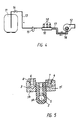
- FIG. 4 shows the arrangement of the connection group piece according to the invention in the heating oil line between an oil tank 11 and a burner 12.
- the feed line 13 from the oil tank 11 is connected to the through bore 3 (not shown) of the connection group piece 10 and contains a ball valve 14 and a filter 15.
- the return line 16 from the burner 12 is connected to the through hole 3 (not shown) of the connection group piece, and the flow line 17 to the burner 12 is connected to the through hole 4 (not shown) of the connection group piece 10.
- the connections of the bores 2, 3 and 4 opposite the three connection points of the lines 13, 16 and 17 are closed by plugs.
- On the connection group piece 10 are three heating oil automatic vent 18, e.g. Wöma breather Flow Control, screwed on.
- connection group piece according to the invention generally consists of light metal, e.g. an aluminum alloy. It is manufactured as an extruded profile piece with subsequent drilling of the connection holes 5,6,7.
- connection group piece shown in cross section in FIG. 5 consists of three housing sub-blocks 1 a , 1 b and 1 c , each of which contains only one through hole 2, 3 or 4 with the connection holes 5, 6 or 7.
- the sub-blocks 1 a , 1 b , 1 c are practically combined to form a housing block.
Landscapes
- Engineering & Computer Science (AREA)
- General Engineering & Computer Science (AREA)
- Mechanical Engineering (AREA)
- Chemical & Material Sciences (AREA)
- Combustion & Propulsion (AREA)
- Feeding And Controlling Fuel (AREA)
- Self-Closing Valves And Venting Or Aerating Valves (AREA)
- Liquid Carbonaceous Fuels (AREA)
- Heat Treatment Of Steel (AREA)
- Pressure Welding/Diffusion-Bonding (AREA)
- Housings, Intake/Discharge, And Installation Of Fluid Heaters (AREA)
Description
- Die Erfindung betrifft ein Anschlußgruppenstück für automatische Heizölentlüfter.
- Aus US-A-2 974 724 ist ein Luftablaßventil einer Heizölleitung bekannt, dessen Handgriff als Schale ausgebildet ist, so daß bei der Entlüftung mit austretendes Öl in der Schale aufgefangen werden kann. Das Ventil besteht aus einem horizontalen Rohrstück mit einem senkrecht dazu ausgerichteten Schenkel mit Gewindebohrung, in die der an den schalenförmigen Handgriff angeformte Ventilkörper eingeschraubt ist. Das bekannte Gerät hat nur einen einzigen Ventilanschluß. Es ist auch nicht für den Anschluß automatischer Heizölentlüfter geeignet, die von dem zu entlüftenden Ölstrom durchflossen werden und je Entlüfter drei Anschlüsse erfordern.
- Der Erfindung liegt die Aufgabe zugrunde, eine Vorrichtung zu schaffen, durch welche die Montage von mehreren Heizölentlüftern vereinfacht wird, so daß ein geringerer Zeitaufwand benötigt wird. Ferner soll eine solche Vorrichtung geschaffen werden, die nur mit einigen Handgriffen auf höhere Leistung erweitert werden kann.
- Diese Aufgabe wird durch ein Anschlußgruppenstück für automatische Heizölentlüfter gelöst, das gekennzeichnet ist durch einen Gehäuseblock mit einer durchgehenden Bohrung für den Anschluß der Zulaufleitung von einem Heizöltank, einer durchgehenden Bohrung für den Anschluß der Rücklaufleitung vom Brenner, einer durchgehenden Bohrung für den Anschluß der Vorlaufleitung zum Brenner und Anschlußbohrungen an die drei durchgehenden Bohrungen für den Anschluß von parallel geschalteten, in Reihe angeordneten Heizölentlüftern. Das erfindungsgemäße Anschlußgruppenstück kommt ohne eine aufwendige Montage aus, weil die Parallelschaltung der Heizölentlüfter durch die Bohrungen in dem Block fest vorgegeben ist. Es ist nur erforderlich, die Heizölentlüfter an die Anschlußbohrungen und die genannten Leitungen an die entsprechenden durchgehenden Bohrungen anzuschließen und noch offene Bohrungen ebenfalls durch Schrauben zu verschliessen. Vorzugsweise ist der Anschluß von bis zu drei Heizölentlüftern vorgesehen.
- Bei dem bevorzugten Anschlußgruppenstück der Erfindung sind die durchgehenden Bohrungen beidendig mit Gewinde versehen. Für die Erweiterung auf eine höhere Leistung können zwei Anschlußgruppenstücke durch Verschraubungen verbunden werden.
- Das erfindungsgemäße Anschlußgruppenstick ist für den Saug- und Druckbetrieb der Heizölentlüfter geeignet.
- Das erfindungsgemäße Anschlußgruppenstück wird an Hand der Zeichnung näher beschrieben. Es zeigen
- Figur 1 eine Seitenansicht des Anschlußgruppenstücks, teilweise im Schnitt;
- Figur 2 eine Draufsicht der Anschlußleiste für die Rücklaufleitungen vom Brenner;
- Figur 3 einen Schnitt nach der Linie A-A der Figur 1,
- Figur 4 die Anordnung des Anschlußgruppenstücks in einer Ölleitung, und
- Figur 5 einen Schnitt analog zu Fig. 3 einer zweiten Ausführungsform des erfindungsgemäßen Anschlußgruppenstücks.
- Nach den Figuren 1 bis 3 besteht das Anschlußgruppenstück aus einem Gehäuseblock 1 mit einer durchgehenden Bohrung 2 für den Anschluß der Zulaufleitung vom Heizöltank, einer durchgehenden Bohrung 3 für den Anschluß der Rücklaufleitung von dem Brenner und einer durchgehenden Leitung 4 für den Anschluß der Vorlaufleitung zum Brenner. Die durchgehenden Bohrungen 2-4 haben beidendig Innengewinde 2a,2b, 3a,3b für den Anschluß der genannten Leitungen bzw. eines weiteren Anschlußgruppenstücks zwecks Erweiterung der Leistung. Das dargestellte Anschlußgruppenstück ist für den Anschluß von bis zu drei Heizölentlüftern geeignet. Demzufolge hat die durchgehende Bohrung 2 drei Anschlußbohrungen 5 für den Anschluß der Tankzulaufstutzen der Heizölentlüfter. Die durchgehende Leitung 3 hat ebenfalls drei Anschlußbohrungen 6 für den Anschluß des Brennerrücklaufstutzens des Heizölentlüfters. Schließlich hat die durchgehende Leitung 4 ebenfalls drei Anschlußbohrungen 7 für den Anschluß des vorlaufstutzens der Heizölentlüfter. Bewegliche Teile enthält das erfindungsgemäße Anschlußgruppenstück nicht.
- Figur 4 zeigt die Anordnung des erfindungsgemäßen Anschlußgruppenstücks in der Heizölleitung zwischen einem Öltank 11 und einem Brenner 12. Die Zulaufleitung 13 vom Öltank 11 ist an die durchgehende Bohrung 3 (nicht dargestellt) des Anschlußgruppenstücks 10 angeschlossen und enthält einen Kugelhahn 14 und ein Filter 15. Die Rücklaufleitung 16 von dem Brenner 12 ist an die durchgehende Bohrung 3 (nicht dargestellt) des Anschlußgruppenstücks angeschlossen, und die Vorlaufleitung 17 zum Brenner 12 ist an die durchgehende Bohrung 4 (nicht dargestellt) des Anschlußgruppenstücks 10 angeschlossen. Die den drei Anschlußstellen der Leitungen 13, 16 und 17 entgegengesetzten Anschlüsse der Bohrungen 2,3 bzw. 4 sind durch Stopfen verschlossen. Auf das Anschlußgruppenstück 10 sind drei Heizöl-Automatikentlüfter 18, z.B. Wöma-Entlüfter Flow Control, aufgeschraubt.
- Das erfindungsgemäße Anschlußgruppenstück besteht im allgemeinen aus Leichtmetall, z.B. einer Aluminiumlegierung. Es wird als Strangpreßprofilstück hergestellt mit nachträglicher Einbringung der Anschlußbohrungen 5,6,7.
- Das in Fig. 5 im Querschnitt gezeigte Anschlußgruppenstück besteht aus drei Gehäuseteilblöcken 1a, 1b und 1c, die jeweils nur eine durchgehende Bohrung 2,3 bzw. 4 mit den Anschlußbohrungen 5, 6 bzw. 7 enthalten. Durch die Montage der Entlüfter 18 werden die Teilblöcke 1a,1b,1cpraktisch zu einem Gehäuseblock vereinigt.
-
- 1
- Gehäuseblock
- 2
- durchgehende Bohrung
- 2a
- Innengewinde
- 2b
- Innengewinde
- 3
- durchgehende Bohrung
- 3a
- Innengewinde
- 3b
- Innengewinde
- 4
- durchgehende Bohrung
- 5
- Anschlußbohrung
- 6
- Anschlußbohrung
- 7
- Anschlußbohrung
- 8
- Anschlußleiste
- 10
- Anschlußgruppenstück
- 11
- Öltank
- 12
- Brenner
- 13
- Zulaufleitung
- 14
- Kugelhahn
- 15
- Filter
- 16
- Rücklaufleitung
- 17
- Vorlaufleitung
- 18
- Heizölautomatikentlüfter
Claims (6)
- Anschlußgruppenstück für automatische Heizölentlüfter, mit einem Gehäuseblock (1) mit einer durchgehenden Bohrung (2) für den Anschluß der Zulaufleitung (13) von einem Heizöltank (11), einer durchgehenden Bohrung (3) für den Anschluß der Rücklaufleitung (16) von einem Brenner (12), einer durchgehenden Bohrung (4) für den Anschluß der Vorlaufleitung (17) zum Brenner (12) und Anschlußbohrungen (5,6,7) an die drei durchgehenden Bohrungen (2 bzw. 3 bzw. 4) für den Anschluß der parallel geschalteten, in Reihe angeordneten Heizölentlüfter (18) an die drei Bohrungen (2, 3 und 4).
- Anschlußgruppenstück nach Anspruch 1, dadurch gekennzeichnet, daß die durchgehenden Bohrungen (2,3,4) beidendig mit Gewinde (2a,2b; 3a,3b) versehen sind.
- Anschlußgruppenstück nach Anspruch 1 oder 2, dadurch gekennzeichnet, daß es für den Saug- und Druckbetrieb der Heizölentlüfter geeignet ist.
- Anschlußgruppenstück nach einem der Ansprüche 1 bis 3, dadurch gekennzeichnet, daß es im wesentlichen als Strangpreßprofilstück aus Leichtmetall hergestellt ist.
- Anschlußgruppenstück nach einem der Ansprüche 1 bis 4, dadurch gekennzeichnet, daß es Anschlußbohrungen (5,6,7) für den Anschluß von zwei oder drei Heizölentlüftern (18) enthält.
- Anschlußgruppenstück nach einem der Ansprüche 1 bus 5, dadurch gekennzeichnet, daß der Gehäuseblock (1) aus drei Teilblöcken (1a,1b,1c) mit je einer durchgehenden Bohrung (2 bzw. 3 bzw. 4) besteht, die durch die aufgeschraubten Heizölentlüfter (18) zusammengespannt sind.
Applications Claiming Priority (2)
| Application Number | Priority Date | Filing Date | Title |
|---|---|---|---|
| DE9308951U DE9308951U1 (de) | 1993-06-16 | 1993-06-16 | Anschlußgruppenstück für automatische Heizölentlüfter |
| DE9308951U | 1993-06-16 |
Publications (3)
| Publication Number | Publication Date |
|---|---|
| EP0629819A2 EP0629819A2 (de) | 1994-12-21 |
| EP0629819A3 EP0629819A3 (de) | 1995-05-24 |
| EP0629819B1 true EP0629819B1 (de) | 1997-08-06 |
Family
ID=6894472
Family Applications (1)
| Application Number | Title | Priority Date | Filing Date |
|---|---|---|---|
| EP94109134A Expired - Lifetime EP0629819B1 (de) | 1993-06-16 | 1994-06-15 | Anschlussgruppenstück für automatische Heizölentlüfter |
Country Status (4)
| Country | Link |
|---|---|
| EP (1) | EP0629819B1 (de) |
| AT (1) | ATE156580T1 (de) |
| DE (2) | DE9308951U1 (de) |
| ES (1) | ES2105423T3 (de) |
Cited By (1)
| Publication number | Priority date | Publication date | Assignee | Title |
|---|---|---|---|---|
| EP1738737A1 (de) | 2005-07-01 | 2007-01-03 | Kettenbach GmbH & CO. KG | Zu formstabilen Formkörpern aushärtendes kondensationsvernetzendes Dentalmaterial |
Families Citing this family (1)
| Publication number | Priority date | Publication date | Assignee | Title |
|---|---|---|---|---|
| DE9418218U1 (de) * | 1994-11-14 | 1994-12-22 | Hans G. Werner GmbH & Co., 70176 Stuttgart | Saug- und Druckaggregat |
Family Cites Families (5)
| Publication number | Priority date | Publication date | Assignee | Title |
|---|---|---|---|---|
| US2974724A (en) * | 1959-01-02 | 1961-03-14 | Levin Alexander | Air bleed valve |
| DE2259835A1 (de) * | 1972-12-07 | 1974-06-12 | Loos Gmbh Eisenwerk Theodor | Oelversorgung einer oelbrenneranlage |
| US4498693A (en) * | 1983-02-22 | 1985-02-12 | Schindele Ernst F | Rail system with passageways for the conduction of fluid flow |
| US4922958A (en) * | 1987-08-03 | 1990-05-08 | Colt Industries Inc. | Manifold for distributing a fluid and method for making same |
| AU3837489A (en) * | 1988-06-16 | 1990-01-12 | Kalevi Viljo Horttonen | A series of distribution and measuring components for a lubricating oil system and a method for manufacturing the principal components of the series |
-
1993
- 1993-06-16 DE DE9308951U patent/DE9308951U1/de not_active Expired - Lifetime
-
1994
- 1994-06-15 DE DE4420838A patent/DE4420838C2/de not_active Expired - Fee Related
- 1994-06-15 AT AT94109134T patent/ATE156580T1/de not_active IP Right Cessation
- 1994-06-15 EP EP94109134A patent/EP0629819B1/de not_active Expired - Lifetime
- 1994-06-15 ES ES94109134T patent/ES2105423T3/es not_active Expired - Lifetime
Cited By (1)
| Publication number | Priority date | Publication date | Assignee | Title |
|---|---|---|---|---|
| EP1738737A1 (de) | 2005-07-01 | 2007-01-03 | Kettenbach GmbH & CO. KG | Zu formstabilen Formkörpern aushärtendes kondensationsvernetzendes Dentalmaterial |
Also Published As
| Publication number | Publication date |
|---|---|
| ATE156580T1 (de) | 1997-08-15 |
| DE4420838A1 (de) | 1995-01-05 |
| ES2105423T3 (es) | 1997-10-16 |
| DE4420838C2 (de) | 1996-06-05 |
| EP0629819A3 (de) | 1995-05-24 |
| DE9308951U1 (de) | 1993-10-28 |
| EP0629819A2 (de) | 1994-12-21 |
Similar Documents
| Publication | Publication Date | Title |
|---|---|---|
| DE102005059014B4 (de) | Ölabscheider für einen Verbrennungsmotor | |
| DE20013534U1 (de) | Vorrichtung zur Rückführung von Gas an einem Verbrennungsmotor | |
| DE2348572C2 (de) | Nachkühler zur Kühlung und Reinigung von komprimierter Luft | |
| EP1676087A1 (de) | Kuhlmittelkuhler eines kraftfahrzeuges | |
| EP0629819B1 (de) | Anschlussgruppenstück für automatische Heizölentlüfter | |
| DE69104335T2 (de) | Kombinierte Vebrennungsluftzu- und Abgasabfuhr. | |
| DE1934193C3 (de) | Ölkühler-Ausbildung und -Befestigung zusammen mit einem ölfilter im wassergekühlten Schmierölkreislauf einer Brennkraftmaschine | |
| DE2335915C3 (de) | Einrichtung zur Halterung und Verbindung von in Reihe geschalteten Vorrichtungen zum Steuern und/oder Konditionieren für Fluide | |
| DE102008033823B4 (de) | Abgasrückführvorrichtung für eine Verbrennungskraftmaschine | |
| DE19856770A1 (de) | Kühlsystem für einen Verbrennungsmotor | |
| DE60123350T2 (de) | Zylinderkopfdeckel für eine Brennmaschine | |
| DE3206965A1 (de) | Oelbehaelter, insbesondere fuer hydraulische lenksysteme | |
| DE69716227T2 (de) | Druckbegrenzungsvorrichtung in einem schmierölkreislauf einer brennkraftmaschine | |
| DE4219679C1 (de) | Ventilanordnung | |
| EP0061565A2 (de) | Entlüftungsstopfen für Heizkörper | |
| DE69903908T2 (de) | Kondensator für Klimaanlage für Fahrzeuge mit integrierter Expansionsvorrichtung | |
| DE4320343C2 (de) | Wärmetauscher, insbesondere Querstromkühler für Brennkraftmaschinen | |
| EP2043754A1 (de) | Flüssigkeits-wärmetauscher-einheit | |
| DE4106297A1 (de) | Querstromkuehler, insbesondere wasser/luft-kuehler fuer brennkraftmaschinen | |
| DE3136374C2 (de) | Kältemittelverdampfer, insbesondere für Klimaanlagen in Kraftfahrzeugen | |
| DE3638617A1 (de) | Fluessigkeitsfilter mit angebauter handpumpe | |
| DE3909176C2 (de) | Druckventileinrichtung für einen Kolbenkompressor | |
| EP1176301A2 (de) | Zylinderkurbelgehäuse einer Brennkraftmaschine | |
| DE202021105847U1 (de) | Ventilsystem für eine Wasserpfeife und Wasserpfeife | |
| DE19642693B4 (de) | Brennkraftmaschine mit Flanschflächen für Anschlußflansche einer mit einem kühlwasserdurchströmten Wärmetauscher verbundenen Vorlauf- und Rücklaufleitung |
Legal Events
| Date | Code | Title | Description |
|---|---|---|---|
| PUAI | Public reference made under article 153(3) epc to a published international application that has entered the european phase |
Free format text: ORIGINAL CODE: 0009012 |
|
| AK | Designated contracting states |
Kind code of ref document: A2 Designated state(s): AT CH ES FR IT LI |
|
| PUAL | Search report despatched |
Free format text: ORIGINAL CODE: 0009013 |
|
| AK | Designated contracting states |
Kind code of ref document: A3 Designated state(s): AT CH ES FR IT LI |
|
| 17P | Request for examination filed |
Effective date: 19950727 |
|
| 17Q | First examination report despatched |
Effective date: 19960402 |
|
| GRAG | Despatch of communication of intention to grant |
Free format text: ORIGINAL CODE: EPIDOS AGRA |
|
| GRAH | Despatch of communication of intention to grant a patent |
Free format text: ORIGINAL CODE: EPIDOS IGRA |
|
| GRAH | Despatch of communication of intention to grant a patent |
Free format text: ORIGINAL CODE: EPIDOS IGRA |
|
| GRAA | (expected) grant |
Free format text: ORIGINAL CODE: 0009210 |
|
| AK | Designated contracting states |
Kind code of ref document: B1 Designated state(s): AT CH ES FR IT LI |
|
| REF | Corresponds to: |
Ref document number: 156580 Country of ref document: AT Date of ref document: 19970815 Kind code of ref document: T |
|
| REG | Reference to a national code |
Ref country code: CH Ref legal event code: EP |
|
| REG | Reference to a national code |
Ref country code: CH Ref legal event code: NV Representative=s name: PATENTANWAELTE GEORG ROEMPLER UND ALDO ROEMPLER |
|
| ITF | It: translation for a ep patent filed | ||
| REG | Reference to a national code |
Ref country code: ES Ref legal event code: FG2A Ref document number: 2105423 Country of ref document: ES Kind code of ref document: T3 |
|
| ET | Fr: translation filed | ||
| PLBE | No opposition filed within time limit |
Free format text: ORIGINAL CODE: 0009261 |
|
| STAA | Information on the status of an ep patent application or granted ep patent |
Free format text: STATUS: NO OPPOSITION FILED WITHIN TIME LIMIT |
|
| 26N | No opposition filed | ||
| PGFP | Annual fee paid to national office [announced via postgrant information from national office to epo] |
Ref country code: ES Payment date: 20000620 Year of fee payment: 7 |
|
| PGFP | Annual fee paid to national office [announced via postgrant information from national office to epo] |
Ref country code: FR Payment date: 20000623 Year of fee payment: 7 |
|
| PGFP | Annual fee paid to national office [announced via postgrant information from national office to epo] |
Ref country code: AT Payment date: 20000629 Year of fee payment: 7 |
|
| PG25 | Lapsed in a contracting state [announced via postgrant information from national office to epo] |
Ref country code: AT Free format text: LAPSE BECAUSE OF NON-PAYMENT OF DUE FEES Effective date: 20010615 |
|
| PG25 | Lapsed in a contracting state [announced via postgrant information from national office to epo] |
Ref country code: ES Free format text: LAPSE BECAUSE OF NON-PAYMENT OF DUE FEES Effective date: 20010616 |
|
| PG25 | Lapsed in a contracting state [announced via postgrant information from national office to epo] |
Ref country code: FR Free format text: LAPSE BECAUSE OF NON-PAYMENT OF DUE FEES Effective date: 20020228 |
|
| PGFP | Annual fee paid to national office [announced via postgrant information from national office to epo] |
Ref country code: CH Payment date: 20020516 Year of fee payment: 9 |
|
| REG | Reference to a national code |
Ref country code: ES Ref legal event code: FD2A Effective date: 20030303 |
|
| PG25 | Lapsed in a contracting state [announced via postgrant information from national office to epo] |
Ref country code: LI Free format text: LAPSE BECAUSE OF NON-PAYMENT OF DUE FEES Effective date: 20030630 Ref country code: CH Free format text: LAPSE BECAUSE OF NON-PAYMENT OF DUE FEES Effective date: 20030630 |
|
| REG | Reference to a national code |
Ref country code: CH Ref legal event code: PL |
|
| PG25 | Lapsed in a contracting state [announced via postgrant information from national office to epo] |
Ref country code: IT Free format text: LAPSE BECAUSE OF NON-PAYMENT OF DUE FEES;WARNING: LAPSES OF ITALIAN PATENTS WITH EFFECTIVE DATE BEFORE 2007 MAY HAVE OCCURRED AT ANY TIME BEFORE 2007. THE CORRECT EFFECTIVE DATE MAY BE DIFFERENT FROM THE ONE RECORDED. Effective date: 20050615 |