EP0629564B1 - Pressure vessel for liquids, arrangement for feeding liquids under pressure and method for bleeding of a hydraulic circuit of a brake - Google Patents
Pressure vessel for liquids, arrangement for feeding liquids under pressure and method for bleeding of a hydraulic circuit of a brake Download PDFInfo
- Publication number
- EP0629564B1 EP0629564B1 EP94401340A EP94401340A EP0629564B1 EP 0629564 B1 EP0629564 B1 EP 0629564B1 EP 94401340 A EP94401340 A EP 94401340A EP 94401340 A EP94401340 A EP 94401340A EP 0629564 B1 EP0629564 B1 EP 0629564B1
- Authority
- EP
- European Patent Office
- Prior art keywords
- fluid
- spout
- container
- seal
- brake
- Prior art date
- Legal status (The legal status is an assumption and is not a legal conclusion. Google has not performed a legal analysis and makes no representation as to the accuracy of the status listed.)
- Expired - Lifetime
Links
Images

Classifications
-
- B—PERFORMING OPERATIONS; TRANSPORTING
- B65—CONVEYING; PACKING; STORING; HANDLING THIN OR FILAMENTARY MATERIAL
- B65D—CONTAINERS FOR STORAGE OR TRANSPORT OF ARTICLES OR MATERIALS, e.g. BAGS, BARRELS, BOTTLES, BOXES, CANS, CARTONS, CRATES, DRUMS, JARS, TANKS, HOPPERS, FORWARDING CONTAINERS; ACCESSORIES, CLOSURES, OR FITTINGS THEREFOR; PACKAGING ELEMENTS; PACKAGES
- B65D83/00—Containers or packages with special means for dispensing contents
- B65D83/14—Containers or packages with special means for dispensing contents for delivery of liquid or semi-liquid contents by internal gaseous pressure, i.e. aerosol containers comprising propellant for a product delivered by a propellant
- B65D83/60—Contents and propellant separated
- B65D83/64—Contents and propellant separated by piston
-
- B—PERFORMING OPERATIONS; TRANSPORTING
- B65—CONVEYING; PACKING; STORING; HANDLING THIN OR FILAMENTARY MATERIAL
- B65D—CONTAINERS FOR STORAGE OR TRANSPORT OF ARTICLES OR MATERIALS, e.g. BAGS, BARRELS, BOTTLES, BOXES, CANS, CARTONS, CRATES, DRUMS, JARS, TANKS, HOPPERS, FORWARDING CONTAINERS; ACCESSORIES, CLOSURES, OR FITTINGS THEREFOR; PACKAGING ELEMENTS; PACKAGES
- B65D47/00—Closures with filling and discharging, or with discharging, devices
- B65D47/36—Closures with frangible parts adapted to be pierced, torn, or removed, to provide discharge openings
- B65D47/38—Closures with frangible parts adapted to be pierced, torn, or removed, to provide discharge openings with piercing means arranged to act subsequently as a valve to control the opening
-
- B—PERFORMING OPERATIONS; TRANSPORTING
- B65—CONVEYING; PACKING; STORING; HANDLING THIN OR FILAMENTARY MATERIAL
- B65D—CONTAINERS FOR STORAGE OR TRANSPORT OF ARTICLES OR MATERIALS, e.g. BAGS, BARRELS, BOTTLES, BOXES, CANS, CARTONS, CRATES, DRUMS, JARS, TANKS, HOPPERS, FORWARDING CONTAINERS; ACCESSORIES, CLOSURES, OR FITTINGS THEREFOR; PACKAGING ELEMENTS; PACKAGES
- B65D51/00—Closures not otherwise provided for
- B65D51/18—Arrangements of closures with protective outer cap-like covers or of two or more co-operating closures
- B65D51/20—Caps, lids, or covers co-operating with an inner closure arranged to be opened by piercing, cutting, or tearing
-
- B—PERFORMING OPERATIONS; TRANSPORTING
- B65—CONVEYING; PACKING; STORING; HANDLING THIN OR FILAMENTARY MATERIAL
- B65D—CONTAINERS FOR STORAGE OR TRANSPORT OF ARTICLES OR MATERIALS, e.g. BAGS, BARRELS, BOTTLES, BOXES, CANS, CARTONS, CRATES, DRUMS, JARS, TANKS, HOPPERS, FORWARDING CONTAINERS; ACCESSORIES, CLOSURES, OR FITTINGS THEREFOR; PACKAGING ELEMENTS; PACKAGES
- B65D2251/00—Details relating to container closures
- B65D2251/0003—Two or more closures
- B65D2251/0006—Upper closure
- B65D2251/0015—Upper closure of the 41-type
-
- B—PERFORMING OPERATIONS; TRANSPORTING
- B65—CONVEYING; PACKING; STORING; HANDLING THIN OR FILAMENTARY MATERIAL
- B65D—CONTAINERS FOR STORAGE OR TRANSPORT OF ARTICLES OR MATERIALS, e.g. BAGS, BARRELS, BOTTLES, BOXES, CANS, CARTONS, CRATES, DRUMS, JARS, TANKS, HOPPERS, FORWARDING CONTAINERS; ACCESSORIES, CLOSURES, OR FITTINGS THEREFOR; PACKAGING ELEMENTS; PACKAGES
- B65D2251/00—Details relating to container closures
- B65D2251/0003—Two or more closures
- B65D2251/0068—Lower closure
- B65D2251/0093—Membrane
Definitions
- the present invention relates to an enclosure containing a pressurized liquid, a pressurized liquid supply assembly and a method for bleeding a hydraulic brake circuit.
- CH-A-533 045 describes an enclosure for liquid of the type comprising a neck, the free end of which is provided with an orifice for the flow of the liquid contained in the enclosure, closed by a perforable seal to release the liquid.
- US-A-5 186 370 discloses an enclosure of the same type which may contain a pressurized liquid.
- the invention particularly aims to allow a single operator to conveniently perform the bleeding of a hydraulic brake circuit for a motor vehicle.
- the invention relates to an enclosure containing a liquid of the aforementioned type, characterized in that the liquid is a brake fluid for a motor vehicle under pressure.
- the invention also relates to an assembly for supplying a hydraulic circuit with pressurized liquid comprising an enclosure as defined above, characterized in that it further comprises means for connecting the neck of the enclosure to a pipe for supplying pressurized liquid to the hydraulic circuit, provided with means for piercing the cover that can be actuated after connection of the neck to the supply pipe.
- connection means comprise a connection intended to be screwed in a leaktight manner on the neck, and a plunger-punch mounted to slide in leaktight manner in the connection between a waiting position and a position for piercing the cover, provided with a channel, one end of which is connected to the supply duct and the other end of which opens out in line with the neck of the enclosure, this latter end comprising a projection for piercing the cover.
- the invention also relates to a method for bleeding a hydraulic brake circuit comprising a brake fluid reservoir and bleeding orifices, characterized in that the reservoir is supplied with pressurized brake fluid with an assembly as defined above, in which the enclosure contains the brake fluid under pressure, so as to pressurize the hydraulic brake circuit, and that the flow of brake fluid is monitored by the open bleeding orifices .
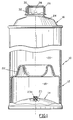
- FIG. 1 shows an enclosure for pressurized liquid according to the invention, designated by the general reference 10, comprising a metal body 12, of generally cylindrical shape, provided at one end with a bottom 14 and at the end opposite from above 16.
- the bottom 14 and the top 16 are fixed to the rest of the body 12 by known means, for example by crimping.
- the body 12 of the enclosure has two internal compartments 18, 20 separated by a piston 22 mounted to slide axially inside the body 12.
- the compartment 18, delimited between the bottom 14 and the piston 22, is filled with a pressurized gas of known type.
- the compartment 20, delimited between the top 16 and the piston 22, is filled with a liquid usually used in hydraulic brake circuits, for example mineral oil.
- the piston 22 tends to impose on the liquid contained in the compartment 20 a pressure of a few atmospheres.
- the enclosure 10 is filled with pressurized gas and with liquid by known means.
- the gas filling means comprise an orifice 23, formed in the bottom 14, closed by a plug 23A made of elastomer.
- the top 16 of the enclosure body has a neck 24 extended by an externally threaded neck 26.
- the free end of the neck 26 has an axial orifice 28 closed by a cover 30 preferably made of a complex material comprising an aluminum layer coated with a polyethylene layer.
- the cover 30 is heat-sealed on the free end of the neck 26, by known means, which makes it possible to ensure a sealed connection between the neck 26 and the cover 30 resistant to the pressure of the liquid contained in the compartment 20.
- a protective cap 32 is screwed onto the neck 26.
- the assembly 34 comprises an enclosure 10 as shown in FIG. 1, the protective cap 32 having been removed from the neck 26, and means 36 for connecting this neck to a flexible conduit 37 for supplying the hydraulic circuit with liquid under pressure, this circuit not being shown in the figures.
- connection means 36 comprise a sleeve 38 forming a connection comprising an end 38A internally threaded, intended to be screwed on the neck 26, and another end 38B reamed forming a guide for a plunger-punch 40 of generally cylindrical shape, mounted to slide axially in the fitting 38 between a waiting position, as shown in FIG. 2, and a position for drilling the cover 30, as shown in FIG. 3.
- the internal surfaces of the two ends 38A, 38B are separated by an annular shoulder 42 forming a support for an annular seal 44 interposed between this shoulder 42 and the free end of the neck 26.
- the punch-punch 40 is pierced axially with a channel 46 for connecting the neck 26 to the flexible conduit 37.
- the end of the channel 46 opening to the right of the neck 26, internal to the fitting 38, is extended by a pointed projection 48 intended to pierce the seal 30.
- the end of the channel 46 opposite the neck 26, external to the fitting 38, forms a nozzle 50 intended to be fitted into a corresponding end of the flexible conduit 37, the seal between this conduit and the nozzle 40 being ensured by a clamping collar 51.
- the seal between the internal surface of the end 38B of the connector and the plunger-punch 40 is ensured in particular by an O-ring 52 disposed in an annular groove 53 formed in the plunger-punch 40.
- the plunger-punch 40 is actuated by a thrust disc 54 fixed by known means on the external part to the connector 38 of this plunger-punch.
- the punch-punch 40 is positioned in the standby position by complementary shoulders 56 formed on the surfaces in contact with this punch-punch and the connector 38.
- the punch-punch 40 is held in the standby position by means elastic of known type, not shown in the figures.
- the protective cap 32 is removed from the neck 26 and the connector 38 is screwed onto the latter, then the end opposite the connector 38 of the flexible conduit 37 is connected in a manner known per se to a brake fluid reservoir to which conventionally connected the hydraulic brake circuit. Then, actuate the pusher-punch 40 by pressing on the disc 54 so that the projection 48 pierces the cover 30, as shown in FIG. 3. After drilling the cover 30, the brake fluid under pressure contained in the enclosure 10 flows through the orifice 28 of the neck 26, the channel 46 and the flexible conduit 37 so as to supply the brake fluid reservoir and put the hydraulic brake circuit under pressure.
- a single operator can simultaneously pressurize the hydraulic brake circuit by actuating the ram plunger 40 of the assembly 34 and monitor the bleeding orifices of the hydraulic brake circuit disposed at the vehicle brakes.
Description
La présente invention concerne une enceinte contenant un liquide sous pression, un ensemble d'approvisionnement en liquide sous pression et un procédé de purge d'un circuit hydraulique de frein.The present invention relates to an enclosure containing a pressurized liquid, a pressurized liquid supply assembly and a method for bleeding a hydraulic brake circuit.
Habituellement, pour effectuer la purge d'un circuit hydraulique de frein pour véhicule automobile, il est nécessaire de faire intervenir au moins deux opérateurs, l'un actionnant la pédale de frein pour mettre le circuit hydraulique sous pression et l'autre surveillant l'écoulement de liquide de frein par les orifices de purge disposés au niveau des freins des roues du véhicule.Usually, to perform the bleeding of a hydraulic brake circuit for a motor vehicle, it is necessary to involve at least two operators, one actuating the brake pedal to pressurize the hydraulic circuit and the other monitoring the brake fluid flow through the bleeding holes arranged at the brakes of the vehicle wheels.
CH-A-533 045 décrit une enceinte pour liquide du type comportant un goulot dont l'extrémité libre est munie d'un orifice d'écoulement du liquide contenu dans l'enceinte, obturé par un opercule perforable pour libérer le liquide. US-A-5 186 370 divulgue une enceinte du même type qui peut contenir un liquide sous pression.CH-A-533 045 describes an enclosure for liquid of the type comprising a neck, the free end of which is provided with an orifice for the flow of the liquid contained in the enclosure, closed by a perforable seal to release the liquid. US-A-5 186 370 discloses an enclosure of the same type which may contain a pressurized liquid.
L'invention a notamment pour but de permettre à un seul opérateur d'effectuer commodément la purge d'un circuit hydraulique de frein pour véhicule automobile.The invention particularly aims to allow a single operator to conveniently perform the bleeding of a hydraulic brake circuit for a motor vehicle.
A cet effet l'invention a pour objet une enceinte contenant un liquide du type précité, caractérisée en ce que le liquide est un liquide de frein pour véhicule automobile sous pression.To this end the invention relates to an enclosure containing a liquid of the aforementioned type, characterized in that the liquid is a brake fluid for a motor vehicle under pressure.
Suivant d'autres caractéristiques de cette enceinte :
- l'opercule est fabriqué dans un matériau complexe en aluminium/polyéthylène et est thermosoudé sur l'extrémité libre du goulot ;
- le liquide a une pression de quelques atmosphères ;
- la pression du liquide est imposée par un piston interne à l'enceinte déplaçable entre une chambre contenant du gaz sous pression et une chambre contenant le liquide ;
- le goulot est fileté extérieurement de manière à permettre le vissage sur ce goulot soit d'un bouchon de protection de l'opercule, soit d'un organe de raccordement du goulot à un circuit hydraulique.
- the cover is made of a complex aluminum / polyethylene material and is heat sealed on the free end of the neck;
- the liquid has a pressure of a few atmospheres;
- the pressure of the liquid is imposed by a piston internal to the enclosure movable between a chamber containing pressurized gas and a chamber containing the liquid;
- the neck is externally threaded so as to allow the screwing on this neck either of a protective cap for the cover, or of a member for connecting the neck to a hydraulic circuit.
L'invention a également pour objet un ensemble d'approvisionnement d'un circuit hydraulique en liquide sous pression comprenant une enceinte telle que définie plus haut, caractérisé en ce qu'il comporte de plus des moyens de raccordement du goulot de l'enceinte à un conduit d'alimentation en liquide sous pression du circuit hydraulique, munis de moyens de perçage de l'opercule actionnables après raccordement du goulot au conduit d'alimentation.The invention also relates to an assembly for supplying a hydraulic circuit with pressurized liquid comprising an enclosure as defined above, characterized in that it further comprises means for connecting the neck of the enclosure to a pipe for supplying pressurized liquid to the hydraulic circuit, provided with means for piercing the cover that can be actuated after connection of the neck to the supply pipe.
De préférence, les moyens de raccordement comprennent un raccord destiné à être vissé de façon étanche sur le goulot, et un poussoir-poinçon monté coulissant de façon étanche dans le raccord entre une position d'attente et une position de perçage de l'opercule, muni d'un canal dont une extrémité est reliée au conduit d'alimentation et dont l'autre extrémité débouche au droit du goulot de l'enceinte, cette dernière extrémité comportant une saillie de perçage de l'opercule.Preferably, the connection means comprise a connection intended to be screwed in a leaktight manner on the neck, and a plunger-punch mounted to slide in leaktight manner in the connection between a waiting position and a position for piercing the cover, provided with a channel, one end of which is connected to the supply duct and the other end of which opens out in line with the neck of the enclosure, this latter end comprising a projection for piercing the cover.
L'invention a également pour objet un procédé de purge d'un circuit hydraulique de frein comportant un réservoir de liquide de frein et des orifices de purge, caractérisé en ce que l'on alimente le réservoir en liquide de frein sous pression avec un ensemble tel que défini plus haut, dans lequel l'enceinte contient le liquide de frein sous pression, de manière à mettre le circuit hydraulique de frein sous pression, et que l'on surveille l'écoulement de liquide de frein par les orifices de purge ouverts.The invention also relates to a method for bleeding a hydraulic brake circuit comprising a brake fluid reservoir and bleeding orifices, characterized in that the reservoir is supplied with pressurized brake fluid with an assembly as defined above, in which the enclosure contains the brake fluid under pressure, so as to pressurize the hydraulic brake circuit, and that the flow of brake fluid is monitored by the open bleeding orifices .
Un exemple de réalisation de l'invention sera décrit ci-dessous en se référant aux dessins annexés dans lesquels :
- la figure 1 est une vue de face, avec des arrachements suivant des coupes longitudinales, d'une enceinte pour liquide sous pression selon l'invention;
- la figure 2 est une vue de face, en coupe longitudinale partielle, d'un ensemble d'approvisionnement en liquide sous pression selon l'invention, le poussoir-poinçon du raccord étant en position d'attente;
- la figure 3 est une vue similaire à la figure 2 dans laquelle le poussoir-poinçon du raccord est en position de perçage ;
- la figure 4 est une vue de détail de la partie cerclée 4 de la figure 3, le poussoir-poinçon étant à nouveau en position d'attente.
- Figure 1 is a front view, with cutaway in longitudinal sections, of an enclosure for pressurized liquid according to the invention;
- Figure 2 is a front view, in partial longitudinal section, of a pressurized liquid supply assembly according to the invention, the push-punch of the connector being in the standby position;
- Figure 3 is a view similar to Figure 2 in which the push-punch of the connector is in the drilling position;
- Figure 4 is a detail view of the
rim portion 4 of Figure 3, the pusher-punch being again in the standby position.
On a représenté sur la figure 1 une enceinte pour liquide sous pression selon l'invention, désignée par la référence générale 10, comportant un corps métallique 12, de forme générale cylindrique, muni à une extrémité d'un fond 14 et à l'extrémité opposée d'un dessus 16.FIG. 1 shows an enclosure for pressurized liquid according to the invention, designated by the
Le fond 14 et le dessus 16 sont fixés sur le reste du corps 12 par des moyens connus, par exemple par sertissage.The
Le corps 12 de l'enceinte comporte deux compartiments internes 18,20 séparés par un piston 22 monté coulissant axialement à l'intérieur du corps 12.The
Le compartiment 18, délimité entre le fond 14 et le piston 22, est rempli d'un gaz sous pression de type connu.The
Le compartiment 20, délimité entre le dessus 16 et le piston 22, est rempli d'un liquide habituellement utilisé dans les circuits hydrauliques de freins, par exemple de l'huile minérale.The
Sous l'effet de la pression du gaz contenu dans le compartiment 18, le piston 22 a tendance à imposer au liquide contenu dans le compartiment 20 une pression de quelques atmosphères.Under the effect of the pressure of the gas contained in the
Le remplissage de l'enceinte 10 en gaz sous pression et en liquide se fait par des moyens connus. Les moyens de remplissage du gaz comprennent un orifice 23, ménagé dans le fond 14, obturé par un bouchon 23A en élastomère.The
Le dessus 16 du corps de l'enceinte comporte un col 24 prolongé par un goulot 26 fileté extérieurement.The top 16 of the enclosure body has a
L'extrémité libre du goulot 26 comporte un orifice axial 28 obturé par un opercule 30 fabriqué de préférence dans un matériau complexe comportant une couche d'aluminium revêtue d'une couche de polyéthylène.The free end of the
L'opercule 30 est thermoscellé sur l'extrémité libre du goulot 26, par des moyens connus, ce qui permet d'assurer une liaison étanche entre le goulot 26 et l'opercule 30 résistant à la pression du liquide contenu dans le compartiment 20.The
Afin de protéger l'opercule 30, un bouchon de protection 32 est vissé sur le goulot 26.In order to protect the
On décrira maintenant un ensemble d'approvisionnement d'un circuit hydraulique en liquide sous pression, en regard des figures 2 à 4, sur lesquelles cet ensemble est désigné par la référence générale 34.We will now describe an assembly for supplying a hydraulic circuit with pressurized liquid, with reference to FIGS. 2 to 4, on which this assembly is designated by the
L'ensemble 34 comporte une enceinte 10 telle que représentée à la figure 1, le bouchon de protection 32 ayant été retiré du goulot 26, et des moyens 36 de raccordement de ce goulot à un conduit flexible 37 d'alimentation du circuit hydraulique en liquide sous pression, ce circuit n'étant pas représenté sur les figures.The
Les moyens de raccordement 36 comprennent un manchon 38 formant raccord comportant une extrémité 38A filetée intérieurement, destinée à être vissée sur le goulot 26, et une autre extrémité 38B alésée formant guide pour un poussoir-poinçon 40 de forme générale cylindrique, monté coulissant axialement dans le raccord 38 entre une position d'attente, telle que représentée à la figure 2, et une position de perçage de l'opercule 30, telle que représentée à la figure 3.The connection means 36 comprise a
Les surfaces internes des deux extrémités 38A,38B sont séparées par un épaulement annulaire 42 formant appui pour un joint d'étanchéité annulaire 44 interposé entre cet épaulement 42 et l'extrémité libre du goulot 26.The internal surfaces of the two
Le poussoir-poinçon 40 est percé axialement d'un canal 46 de raccordement du goulot 26 au conduit flexible 37.The punch-
L'extrémité du canal 46 débouchant au droit du goulot 26, interne au raccord 38, est prolongée par une saillie pointue 48 destinée à percer l'opercule 30. L'extrémité du canal 46 opposée au goulot 26, externe au raccord 38, forme un embout 50 destiné à être emmanché dans une extrémité correspondante du conduit flexible 37, l'étanchéité entre ce conduit et l'embout 40 étant assurée par un collier de serrage 51.The end of the
L'étanchéité entre la surface interne de l'extrémité 38B du raccord et le poussoir-poinçon 40 est assurée notamment par un joint torique 52 disposé dans une gorge annulaire 53 ménagée dans le poussoir-poinçon 40.The seal between the internal surface of the
Le poussoir-poinçon 40 est actionné par un disque de poussée 54 fixé par des moyens connus sur la partie externe au raccord 38 de ce poussoir-poinçon.The plunger-
Le poussoir-poinçon 40 est positionné en position d'attente par des épaulements complémentaires 56 ménagés sur les surfaces en contact de ce poussoir-poinçon et du raccord 38. De préférence le poussoir-poinçon 40 est maintenu en position d'attente par des moyens élastiques de type connu, non représentés sur les figures.The punch-
On décrira maintenant un procédé de purge d'un circuit hydraulique de frein pour véhicule automobile mettant en oeuvre un ensemble 34 tel que représenté sur les figures 2 à 4.A method of bleeding a hydraulic brake circuit for a motor vehicle will now be described. using an
Initialement, on retire le bouchon de protection 32 du goulot 26 et on visse sur ce dernier le raccord 38, puis on raccorde de façon connue en soi l'extrémité opposée au raccord 38 du conduit flexible 37 à un réservoir de liquide de frein auquel est relié de façon classique le circuit hydraulique de frein. Ensuite, on actionne le poussoir-poinçon 40 en appuyant sur le disque 54 de manière que la saillie 48 perce l'opercule 30, comme cela est représenté sur la figure 3. Après perçage de l'opercule 30, le liquide de frein sous pression contenu dans l'enceinte 10 s'écoule à travers l'orifice 28 du goulot 26, le canal 46 et le conduit flexible 37 de manière à alimenter le réservoir de liquide de frein et mettre le circuit hydraulique de frein sous pression.Initially, the
On notera que sous l'effet de la pression du liquide, le poussoir-poinçon 40 est déplacé vers sa position d'attente, comme cela est représenté sur la figure 4.It will be noted that under the effect of the pressure of the liquid, the pusher-
On notera également qu'après vissage du raccord 38 à fond sur le goulot 26, l'étanchéité des moyens 34 de raccordement est assurée ce qui permet d'effectuer le perçage de l'opercule 30 et la libération du liquide sous pression sans risque de fuite.It will also be noted that after screwing the
L'élévation de la pression dans le circuit hydraulique de frein permet la purge de ce dernier.The increase in pressure in the hydraulic brake circuit allows the bleeding of the latter.
Ainsi, un opérateur unique peut simultanément mettre le circuit hydraulique de frein sous pression en actionnant le poussoir-poinçon 40 de l'ensemble 34 et surveiller les orifices de purge du circuit hydraulique de frein disposés au niveau des freins du véhicule.Thus, a single operator can simultaneously pressurize the hydraulic brake circuit by actuating the
Claims (8)
- Container containing a fluid, of the type comprising a spout (26) the free end of which is provided with an outflow opening (28) for the fluid contained in the container, closed off by a seal (30) which can be perforated to release the fluid, characterised in that the fluid is a pressurised brake fluid for motor vehicles.
- Container according to claim 1, characterised in that the seal (30) is made of a complex aluminium/polyethylene material and is heat-sealed over the free end of the spout (26).
- Container according to claim 1 or 2, characterised in that the fluid is at a pressure of several atmospheres.
- Container according to any one of claims 1 to 3, characterised in that the pressure of the fluid is created by a piston (22) inside the container, which is movable between a chamber (18) containing pressurised gas and a chamber (20) containing the fluid.
- Container according to any one of claims 1 to 4, characterised in that the spout (26) is externally threaded so that this spout can be screwed onto either a stopper (32) protecting the seal (30) or a member (38) for connecting the stopper (26) to a hydraulic circuit.
- Unit for supplying a hydraulic circuit with pressurised fluid, comprising a container according to any one of claims 1 to 5, characterized in that it further comprises means (36) for connecting the spout (26) of the container to a pipe (37) for supplying the hydraulic circuit with pressurised fluid, comprising means (40) for piercing the seal (30) which can be actuated after the spout (26) has been connected to the supply pipe.
- Supply unit according to claims 5 and 6 taken together, characterised in that the connecting means (36) comprise a connector (38) intended to be screwed tightly onto the spout (26), and a push-in piercing member (40) slidably mounted in a leaktight manner in the connector (38) between a resting position and a position for piercing the seal, provided with a channel (46) one end (50) of which is connected to the supply pipe (37) whilst the other end opens out level with the spout (26) of the container, this latter end comprising a projection (48) for piercing the seal (30).
- Method of bleeding a hydraulic brake circuit comprising a brake fluid reservoir and bleeding ports, characterised in that the reservoir is supplied with pressurised brake fluid using a unit according to claim 6 or 7, in which the container contains the pressurised brake fluid, so as to pressurise the hydraulic brake circuit, and the outflow of brake fluid through the open bleeding ports is monitored.
Applications Claiming Priority (2)
| Application Number | Priority Date | Filing Date | Title |
|---|---|---|---|
| FR9307422 | 1993-06-18 | ||
| FR9307422A FR2706542B1 (en) | 1993-06-18 | 1993-06-18 | Pressurized fluid enclosure, pressurized fluid supply assembly and bleeding process for a hydraulic brake circuit. |
Publications (2)
| Publication Number | Publication Date |
|---|---|
| EP0629564A1 EP0629564A1 (en) | 1994-12-21 |
| EP0629564B1 true EP0629564B1 (en) | 1997-10-15 |
Family
ID=9448318
Family Applications (1)
| Application Number | Title | Priority Date | Filing Date |
|---|---|---|---|
| EP94401340A Expired - Lifetime EP0629564B1 (en) | 1993-06-18 | 1994-06-15 | Pressure vessel for liquids, arrangement for feeding liquids under pressure and method for bleeding of a hydraulic circuit of a brake |
Country Status (4)
| Country | Link |
|---|---|
| US (1) | US5626173A (en) |
| EP (1) | EP0629564B1 (en) |
| DE (1) | DE69406195T2 (en) |
| FR (1) | FR2706542B1 (en) |
Families Citing this family (8)
| Publication number | Priority date | Publication date | Assignee | Title |
|---|---|---|---|---|
| US5899065A (en) * | 1995-05-15 | 1999-05-04 | Phoenix Systems, L.L.C. | Hydraulic fluid packet and kit containing the same |
| US6539988B1 (en) | 2001-12-28 | 2003-04-01 | Interdynamics, Inc. | Pressurized container adapter for charging automotive systems |
| US6796340B1 (en) | 2003-05-22 | 2004-09-28 | E.F. Products, Inc. | Method and dispenser for pressurized containers used with automobile air conditioning systems |
| US8359146B2 (en) * | 2005-12-15 | 2013-01-22 | Bendix Commercial Vehicle Systems Llc | Single channel roll stability system |
| WO2010091520A1 (en) * | 2009-02-13 | 2010-08-19 | Medmix Systems Ag | Opening aid for tubes |
| US20110041522A1 (en) * | 2009-08-04 | 2011-02-24 | Vincent Carrubba | Adapter system and method |
| US10359220B2 (en) | 2011-02-02 | 2019-07-23 | The Armor All/Stp Products Company | Systems, methods and apparatus for servicing a refrigeration system |
| US10113780B2 (en) | 2011-11-14 | 2018-10-30 | The Armor All/Stp Products Company | Refrigerant charging assemblies and methods of use |
Family Cites Families (13)
| Publication number | Priority date | Publication date | Assignee | Title |
|---|---|---|---|---|
| US2735589A (en) * | 1956-02-21 | Portable device for | ||
| FR800987A (en) * | 1936-01-06 | 1936-07-23 | Unblocker-dispenser adaptable to containers such as collapsible tubes | |
| US2509570A (en) * | 1947-06-21 | 1950-05-30 | Lee William Warden | Device for supplying brake fluid |
| US2670874A (en) * | 1948-10-12 | 1954-03-02 | Edward D Wilkerson | Hydraulic brake system bleeding and filling apparatus |
| US2925937A (en) * | 1957-08-30 | 1960-02-23 | Grand Central Rocket Company | Liquid dispenser |
| US3583491A (en) * | 1969-01-30 | 1971-06-08 | Serlachius Oy | Portable fire extinguisher construction |
| CH533045A (en) * | 1971-03-29 | 1973-01-31 | Roth Handels Gmbh | Screw cap for a container |
| AT332102B (en) * | 1973-10-03 | 1976-09-10 | Fischbach A Kunststoff Kg | HOLLOW CYLINDRICAL EXTRUDED VESSEL |
| FR2552056A1 (en) * | 1983-09-15 | 1985-03-22 | Beyoux Noel | Device for dispensing, on request, a liquid or pasty material such as a lubricant (oil, grease, etc.), glue, and substances intended for producing fluid-tight seals |
| DE3339257A1 (en) * | 1983-10-28 | 1985-05-09 | Heinz Dipl.-Ing. 4937 Lage Stricker | Flexible tank |
| US4785629A (en) * | 1987-06-04 | 1988-11-22 | Ennis Iii James F | Syringe-dispensed brake fluid for filling and purging master cylinder circuit from slave |
| US5186370A (en) * | 1991-02-22 | 1993-02-16 | Ricketts Robert M | Container resealing method and apparatus |
| US5410881A (en) * | 1994-01-24 | 1995-05-02 | Ellis; Martin J. | Universal one man brake bleeding apparatus |
-
1993
- 1993-06-18 FR FR9307422A patent/FR2706542B1/en not_active Expired - Fee Related
-
1994
- 1994-06-15 EP EP94401340A patent/EP0629564B1/en not_active Expired - Lifetime
- 1994-06-15 DE DE69406195T patent/DE69406195T2/en not_active Expired - Fee Related
- 1994-06-20 US US08/262,253 patent/US5626173A/en not_active Expired - Fee Related
Also Published As
| Publication number | Publication date |
|---|---|
| EP0629564A1 (en) | 1994-12-21 |
| US5626173A (en) | 1997-05-06 |
| DE69406195D1 (en) | 1997-11-20 |
| DE69406195T2 (en) | 1998-05-07 |
| FR2706542B1 (en) | 1995-09-29 |
| FR2706542A1 (en) | 1994-12-23 |
Similar Documents
| Publication | Publication Date | Title |
|---|---|---|
| EP0642839B1 (en) | Process and device for storing and dispensing a fluid product held in a container pressurized with a propellant gas | |
| EP0629564B1 (en) | Pressure vessel for liquids, arrangement for feeding liquids under pressure and method for bleeding of a hydraulic circuit of a brake | |
| FR2804666A1 (en) | DISPENSER FOR STORING AT LEAST TWO COMPONENTS AND SELECTIVE DISTRIBUTION OF SINGLE COMPONENT OR MIXTURE THEREOF AND PROCESS FOR IMPLEMENTING THE SAME | |
| EP0462861A1 (en) | Method for packaging a product in a container, ensuring product preservation during storage and the corresponding packaging unit | |
| FR2558126A1 (en) | BRAKING FORCE AMPLIFIER WITH LOW PRESSURE | |
| CA2345735C (en) | Disposable injection device designed to be pre-filled | |
| FR2584952A1 (en) | DEVICE FOR APPLYING A PREDETERMINED QUANTITY OF A LIQUID TO A SURFACE | |
| EP1124739A1 (en) | Pouch reservoir valve | |
| EP2506938B1 (en) | Fluid ejection device | |
| EP0765822B1 (en) | Device with a safety valve for dispensing liquid under pressure | |
| CH658637A5 (en) | DROPPER ASSEMBLY. | |
| EP0874761B1 (en) | Nozzle for dispensing a liquid or pasty material | |
| EP1069355B1 (en) | Safety valve for pressure vessel | |
| FR2619884A1 (en) | PILOTED SAFETY VALVE | |
| EP1985906B1 (en) | Adapter for testing or filling a fluid container or circuit with a neck | |
| FR2722416A1 (en) | Fire extinguisher with reservoir for extinguishant | |
| US8316871B2 (en) | Device and process for perforating a duct fitted with a connector seat | |
| EP0428901B1 (en) | Pressure reducer which can be neutralised | |
| FR2681685A1 (en) | LEVEL DETECTOR WITHIN A CONTAINER CONTAINING A GRANULAR MATERIAL, ESPECIALLY SAND, PARTICULARLY INSIDE A SANDBLASTER ASSOCIATED WITH A DRIVE WHEEL. | |
| EP3947194A1 (en) | Recyclable aerosol can with depressurisation system and tool for depressurising such a can | |
| FR2708329A1 (en) | Submerged connection device for hydraulic couplings | |
| FR2649325A1 (en) | Improved extinguisher | |
| EP1634002B1 (en) | Filler and drain valve and cleaning tools for a pressure-fluid cylinder | |
| FR2496606A3 (en) | Receptacle for dispensing sealing paste - has piston membrane with pressurised drive gas and valve controlled by pressing nozzle | |
| FR2517220A1 (en) | Fluid distributor for container - has housing which clips onto spout and has stem piercing cap |
Legal Events
| Date | Code | Title | Description |
|---|---|---|---|
| PUAI | Public reference made under article 153(3) epc to a published international application that has entered the european phase |
Free format text: ORIGINAL CODE: 0009012 |
|
| AK | Designated contracting states |
Kind code of ref document: A1 Designated state(s): BE DE FR GB NL |
|
| 17P | Request for examination filed |
Effective date: 19941207 |
|
| 17Q | First examination report despatched |
Effective date: 19960201 |
|
| GRAG | Despatch of communication of intention to grant |
Free format text: ORIGINAL CODE: EPIDOS AGRA |
|
| GRAH | Despatch of communication of intention to grant a patent |
Free format text: ORIGINAL CODE: EPIDOS IGRA |
|
| GRAH | Despatch of communication of intention to grant a patent |
Free format text: ORIGINAL CODE: EPIDOS IGRA |
|
| GRAA | (expected) grant |
Free format text: ORIGINAL CODE: 0009210 |
|
| AK | Designated contracting states |
Kind code of ref document: B1 Designated state(s): BE DE FR GB NL |
|
| REF | Corresponds to: |
Ref document number: 69406195 Country of ref document: DE Date of ref document: 19971120 |
|
| GBT | Gb: translation of ep patent filed (gb section 77(6)(a)/1977) |
Effective date: 19980116 |
|
| PLBE | No opposition filed within time limit |
Free format text: ORIGINAL CODE: 0009261 |
|
| STAA | Information on the status of an ep patent application or granted ep patent |
Free format text: STATUS: NO OPPOSITION FILED WITHIN TIME LIMIT |
|
| 26N | No opposition filed | ||
| PGFP | Annual fee paid to national office [announced via postgrant information from national office to epo] |
Ref country code: NL Payment date: 20000629 Year of fee payment: 7 Ref country code: FR Payment date: 20000629 Year of fee payment: 7 |
|
| PGFP | Annual fee paid to national office [announced via postgrant information from national office to epo] |
Ref country code: GB Payment date: 20000630 Year of fee payment: 7 |
|
| PGFP | Annual fee paid to national office [announced via postgrant information from national office to epo] |
Ref country code: DE Payment date: 20000720 Year of fee payment: 7 |
|
| PGFP | Annual fee paid to national office [announced via postgrant information from national office to epo] |
Ref country code: BE Payment date: 20000801 Year of fee payment: 7 |
|
| PG25 | Lapsed in a contracting state [announced via postgrant information from national office to epo] |
Ref country code: GB Free format text: LAPSE BECAUSE OF NON-PAYMENT OF DUE FEES Effective date: 20010615 |
|
| PG25 | Lapsed in a contracting state [announced via postgrant information from national office to epo] |
Ref country code: BE Free format text: LAPSE BECAUSE OF NON-PAYMENT OF DUE FEES Effective date: 20010630 |
|
| BERE | Be: lapsed |
Owner name: SAFET EMBAMET Effective date: 20010630 |
|
| PG25 | Lapsed in a contracting state [announced via postgrant information from national office to epo] |
Ref country code: NL Free format text: LAPSE BECAUSE OF NON-PAYMENT OF DUE FEES Effective date: 20020101 |
|
| GBPC | Gb: european patent ceased through non-payment of renewal fee |
Effective date: 20010615 |
|
| PG25 | Lapsed in a contracting state [announced via postgrant information from national office to epo] |
Ref country code: FR Free format text: LAPSE BECAUSE OF NON-PAYMENT OF DUE FEES Effective date: 20020228 |
|
| NLV4 | Nl: lapsed or anulled due to non-payment of the annual fee |
Effective date: 20020101 |
|
| PG25 | Lapsed in a contracting state [announced via postgrant information from national office to epo] |
Ref country code: DE Free format text: LAPSE BECAUSE OF NON-PAYMENT OF DUE FEES Effective date: 20020403 |