EP0629564B1 - Druckgefäss für Flüssigkeiten, Anordnung zur Beschickung mit Flüssigkeiten unter Druck und Verfahren zur Hydraulikkreislaufentlüftung einer Bremse - Google Patents
Druckgefäss für Flüssigkeiten, Anordnung zur Beschickung mit Flüssigkeiten unter Druck und Verfahren zur Hydraulikkreislaufentlüftung einer Bremse Download PDFInfo
- Publication number
- EP0629564B1 EP0629564B1 EP94401340A EP94401340A EP0629564B1 EP 0629564 B1 EP0629564 B1 EP 0629564B1 EP 94401340 A EP94401340 A EP 94401340A EP 94401340 A EP94401340 A EP 94401340A EP 0629564 B1 EP0629564 B1 EP 0629564B1
- Authority
- EP
- European Patent Office
- Prior art keywords
- fluid
- spout
- container
- seal
- brake
- Prior art date
- Legal status (The legal status is an assumption and is not a legal conclusion. Google has not performed a legal analysis and makes no representation as to the accuracy of the status listed.)
- Expired - Lifetime
Links
- 230000000740 bleeding effect Effects 0.000 title claims description 14
- 238000000034 method Methods 0.000 title claims description 5
- 239000007788 liquid Substances 0.000 title description 26
- 239000012530 fluid Substances 0.000 claims description 23
- 229910052782 aluminium Inorganic materials 0.000 claims description 4
- XAGFODPZIPBFFR-UHFFFAOYSA-N aluminium Chemical compound [Al] XAGFODPZIPBFFR-UHFFFAOYSA-N 0.000 claims description 4
- 239000004698 Polyethylene Substances 0.000 claims description 3
- 229920000573 polyethylene Polymers 0.000 claims description 3
- 239000004411 aluminium Substances 0.000 claims description 2
- 239000000463 material Substances 0.000 claims description 2
- 230000000284 resting effect Effects 0.000 claims 1
- 230000001681 protective effect Effects 0.000 description 4
- 238000005553 drilling Methods 0.000 description 3
- 230000000694 effects Effects 0.000 description 2
- -1 polyethylene Polymers 0.000 description 2
- 230000000295 complement effect Effects 0.000 description 1
- 239000011365 complex material Substances 0.000 description 1
- 238000002788 crimping Methods 0.000 description 1
- 229920001971 elastomer Polymers 0.000 description 1
- 239000000806 elastomer Substances 0.000 description 1
- 229910052751 metal Inorganic materials 0.000 description 1
- 239000002184 metal Substances 0.000 description 1
- 239000002480 mineral oil Substances 0.000 description 1
- 235000010446 mineral oil Nutrition 0.000 description 1
- 238000012544 monitoring process Methods 0.000 description 1
- 238000007789 sealing Methods 0.000 description 1
Images

Classifications
-
- B—PERFORMING OPERATIONS; TRANSPORTING
- B65—CONVEYING; PACKING; STORING; HANDLING THIN OR FILAMENTARY MATERIAL
- B65D—CONTAINERS FOR STORAGE OR TRANSPORT OF ARTICLES OR MATERIALS, e.g. BAGS, BARRELS, BOTTLES, BOXES, CANS, CARTONS, CRATES, DRUMS, JARS, TANKS, HOPPERS, FORWARDING CONTAINERS; ACCESSORIES, CLOSURES, OR FITTINGS THEREFOR; PACKAGING ELEMENTS; PACKAGES
- B65D83/00—Containers or packages with special means for dispensing contents
- B65D83/14—Containers for dispensing liquid or semi-liquid contents by internal gaseous pressure, i.e. aerosol containers comprising propellant
- B65D83/60—Containers for dispensing liquid or semi-liquid contents by internal gaseous pressure, i.e. aerosol containers comprising propellant with contents and propellant separated
- B65D83/64—Containers for dispensing liquid or semi-liquid contents by internal gaseous pressure, i.e. aerosol containers comprising propellant with contents and propellant separated by pistons
-
- B—PERFORMING OPERATIONS; TRANSPORTING
- B65—CONVEYING; PACKING; STORING; HANDLING THIN OR FILAMENTARY MATERIAL
- B65D—CONTAINERS FOR STORAGE OR TRANSPORT OF ARTICLES OR MATERIALS, e.g. BAGS, BARRELS, BOTTLES, BOXES, CANS, CARTONS, CRATES, DRUMS, JARS, TANKS, HOPPERS, FORWARDING CONTAINERS; ACCESSORIES, CLOSURES, OR FITTINGS THEREFOR; PACKAGING ELEMENTS; PACKAGES
- B65D47/00—Closures with filling and discharging, or with discharging, devices
- B65D47/36—Closures with frangible parts adapted to be pierced, torn or removed, to provide discharge openings
- B65D47/38—Closures with frangible parts adapted to be pierced, torn or removed, to provide discharge openings with piercing means arranged to act subsequently as a valve to control the opening
-
- B—PERFORMING OPERATIONS; TRANSPORTING
- B65—CONVEYING; PACKING; STORING; HANDLING THIN OR FILAMENTARY MATERIAL
- B65D—CONTAINERS FOR STORAGE OR TRANSPORT OF ARTICLES OR MATERIALS, e.g. BAGS, BARRELS, BOTTLES, BOXES, CANS, CARTONS, CRATES, DRUMS, JARS, TANKS, HOPPERS, FORWARDING CONTAINERS; ACCESSORIES, CLOSURES, OR FITTINGS THEREFOR; PACKAGING ELEMENTS; PACKAGES
- B65D51/00—Closures not otherwise provided for
- B65D51/18—Arrangements of closures with protective outer cap-like covers or of two or more co-operating closures
- B65D51/20—Caps, lids, or covers co-operating with an inner closure arranged to be opened by piercing, cutting, or tearing
-
- B—PERFORMING OPERATIONS; TRANSPORTING
- B65—CONVEYING; PACKING; STORING; HANDLING THIN OR FILAMENTARY MATERIAL
- B65D—CONTAINERS FOR STORAGE OR TRANSPORT OF ARTICLES OR MATERIALS, e.g. BAGS, BARRELS, BOTTLES, BOXES, CANS, CARTONS, CRATES, DRUMS, JARS, TANKS, HOPPERS, FORWARDING CONTAINERS; ACCESSORIES, CLOSURES, OR FITTINGS THEREFOR; PACKAGING ELEMENTS; PACKAGES
- B65D2251/00—Details relating to container closures
- B65D2251/0003—Two or more closures
- B65D2251/0006—Upper closure
- B65D2251/0015—Upper closure of the 41-type
-
- B—PERFORMING OPERATIONS; TRANSPORTING
- B65—CONVEYING; PACKING; STORING; HANDLING THIN OR FILAMENTARY MATERIAL
- B65D—CONTAINERS FOR STORAGE OR TRANSPORT OF ARTICLES OR MATERIALS, e.g. BAGS, BARRELS, BOTTLES, BOXES, CANS, CARTONS, CRATES, DRUMS, JARS, TANKS, HOPPERS, FORWARDING CONTAINERS; ACCESSORIES, CLOSURES, OR FITTINGS THEREFOR; PACKAGING ELEMENTS; PACKAGES
- B65D2251/00—Details relating to container closures
- B65D2251/0003—Two or more closures
- B65D2251/0068—Lower closure
- B65D2251/0093—Membrane
Definitions
- the present invention relates to an enclosure containing a pressurized liquid, a pressurized liquid supply assembly and a method for bleeding a hydraulic brake circuit.
- CH-A-533 045 describes an enclosure for liquid of the type comprising a neck, the free end of which is provided with an orifice for the flow of the liquid contained in the enclosure, closed by a perforable seal to release the liquid.
- US-A-5 186 370 discloses an enclosure of the same type which may contain a pressurized liquid.
- the invention particularly aims to allow a single operator to conveniently perform the bleeding of a hydraulic brake circuit for a motor vehicle.
- the invention relates to an enclosure containing a liquid of the aforementioned type, characterized in that the liquid is a brake fluid for a motor vehicle under pressure.
- the invention also relates to an assembly for supplying a hydraulic circuit with pressurized liquid comprising an enclosure as defined above, characterized in that it further comprises means for connecting the neck of the enclosure to a pipe for supplying pressurized liquid to the hydraulic circuit, provided with means for piercing the cover that can be actuated after connection of the neck to the supply pipe.
- connection means comprise a connection intended to be screwed in a leaktight manner on the neck, and a plunger-punch mounted to slide in leaktight manner in the connection between a waiting position and a position for piercing the cover, provided with a channel, one end of which is connected to the supply duct and the other end of which opens out in line with the neck of the enclosure, this latter end comprising a projection for piercing the cover.
- the invention also relates to a method for bleeding a hydraulic brake circuit comprising a brake fluid reservoir and bleeding orifices, characterized in that the reservoir is supplied with pressurized brake fluid with an assembly as defined above, in which the enclosure contains the brake fluid under pressure, so as to pressurize the hydraulic brake circuit, and that the flow of brake fluid is monitored by the open bleeding orifices .
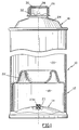
- FIG. 1 shows an enclosure for pressurized liquid according to the invention, designated by the general reference 10, comprising a metal body 12, of generally cylindrical shape, provided at one end with a bottom 14 and at the end opposite from above 16.
- the bottom 14 and the top 16 are fixed to the rest of the body 12 by known means, for example by crimping.
- the body 12 of the enclosure has two internal compartments 18, 20 separated by a piston 22 mounted to slide axially inside the body 12.
- the compartment 18, delimited between the bottom 14 and the piston 22, is filled with a pressurized gas of known type.
- the compartment 20, delimited between the top 16 and the piston 22, is filled with a liquid usually used in hydraulic brake circuits, for example mineral oil.
- the piston 22 tends to impose on the liquid contained in the compartment 20 a pressure of a few atmospheres.
- the enclosure 10 is filled with pressurized gas and with liquid by known means.
- the gas filling means comprise an orifice 23, formed in the bottom 14, closed by a plug 23A made of elastomer.
- the top 16 of the enclosure body has a neck 24 extended by an externally threaded neck 26.
- the free end of the neck 26 has an axial orifice 28 closed by a cover 30 preferably made of a complex material comprising an aluminum layer coated with a polyethylene layer.
- the cover 30 is heat-sealed on the free end of the neck 26, by known means, which makes it possible to ensure a sealed connection between the neck 26 and the cover 30 resistant to the pressure of the liquid contained in the compartment 20.
- a protective cap 32 is screwed onto the neck 26.
- the assembly 34 comprises an enclosure 10 as shown in FIG. 1, the protective cap 32 having been removed from the neck 26, and means 36 for connecting this neck to a flexible conduit 37 for supplying the hydraulic circuit with liquid under pressure, this circuit not being shown in the figures.
- connection means 36 comprise a sleeve 38 forming a connection comprising an end 38A internally threaded, intended to be screwed on the neck 26, and another end 38B reamed forming a guide for a plunger-punch 40 of generally cylindrical shape, mounted to slide axially in the fitting 38 between a waiting position, as shown in FIG. 2, and a position for drilling the cover 30, as shown in FIG. 3.
- the internal surfaces of the two ends 38A, 38B are separated by an annular shoulder 42 forming a support for an annular seal 44 interposed between this shoulder 42 and the free end of the neck 26.
- the punch-punch 40 is pierced axially with a channel 46 for connecting the neck 26 to the flexible conduit 37.
- the end of the channel 46 opening to the right of the neck 26, internal to the fitting 38, is extended by a pointed projection 48 intended to pierce the seal 30.
- the end of the channel 46 opposite the neck 26, external to the fitting 38, forms a nozzle 50 intended to be fitted into a corresponding end of the flexible conduit 37, the seal between this conduit and the nozzle 40 being ensured by a clamping collar 51.
- the seal between the internal surface of the end 38B of the connector and the plunger-punch 40 is ensured in particular by an O-ring 52 disposed in an annular groove 53 formed in the plunger-punch 40.
- the plunger-punch 40 is actuated by a thrust disc 54 fixed by known means on the external part to the connector 38 of this plunger-punch.
- the punch-punch 40 is positioned in the standby position by complementary shoulders 56 formed on the surfaces in contact with this punch-punch and the connector 38.
- the punch-punch 40 is held in the standby position by means elastic of known type, not shown in the figures.
- the protective cap 32 is removed from the neck 26 and the connector 38 is screwed onto the latter, then the end opposite the connector 38 of the flexible conduit 37 is connected in a manner known per se to a brake fluid reservoir to which conventionally connected the hydraulic brake circuit. Then, actuate the pusher-punch 40 by pressing on the disc 54 so that the projection 48 pierces the cover 30, as shown in FIG. 3. After drilling the cover 30, the brake fluid under pressure contained in the enclosure 10 flows through the orifice 28 of the neck 26, the channel 46 and the flexible conduit 37 so as to supply the brake fluid reservoir and put the hydraulic brake circuit under pressure.
- a single operator can simultaneously pressurize the hydraulic brake circuit by actuating the ram plunger 40 of the assembly 34 and monitor the bleeding orifices of the hydraulic brake circuit disposed at the vehicle brakes.
Landscapes
- Engineering & Computer Science (AREA)
- Mechanical Engineering (AREA)
- Chemical & Material Sciences (AREA)
- Dispersion Chemistry (AREA)
- Valves And Accessory Devices For Braking Systems (AREA)
- Closures For Containers (AREA)
Claims (8)
- Behälter, der eine Flüssigkeit enthält, mit einem Hals (26), dessen freies Ende mit einer Ausgießöffnung (28) für die Flüssigkeit in dem Behälter versehen ist, die durch einen Verschluß (30) verschlossen ist, der zum Auslassen der Flüssigkeit perforierbar ist, dadurch gekennzeichnet, daß die Flüssigkeit eine unter Druck stehende Bremsflüssigkeit für Kraftfahrzeuge ist.
- Behälter nach Anspruch 1, dadurch gekennzeichnet, daß der Verschluß (30) aus einem kombinierten Material aus Aluminium und Polyethylen besteht und auf das freie Ende des Halses (26) durch Thermoschweißen aufgebracht ist.
- Behälter nach Anspruch 1 oder 2, dadurch gekennzeichnet, daß die Flüssigkeit einen Druck von mehreren Atmosphären aufweist.
- Behälter nach einem der Ansprüche 1 bis 3, dadurch gekennzeichnet, daß der Druck der Flüssigkeit durch einen Kolben (22) aufgebracht wird, der im Inneren des Behälters verschiebbar zwischen einer Kammer (18), die ein Druckgas enthält, und einer Kammer (20), die die Flüssigkeit enthält, angeordnet ist.
- Behälter nach einem der Ansprüche 1 bis 4, dadurch gekennzeichnet, daß der Hals (26) ein Außengewinde aufweist, das das Aufschrauben einer Schutzkappe (32) für den Verschluß (30) oder eines Anschlußorgans (38) zur Verbindung des Halses (26) mit einem Hydraulikkreis gestattet.
- Anordnung zur Versorgung eines Hydraulikkreises mit Flüssigkeit unter Druck, mit einem Behälter gemäß einem der Ansprüche 1 bis 5, dadurch gekennzeichnet, daß der Behälter im übrigen Mittel (36) zur Verbindung des Halses (26) des Behälters mit einer Leitung (37) zum Zuführen von Druckflüssigkeit zum Hydraulikkreis umfaßt, und daß Mittel (40) zum Durchstoßen des Verschlusses (30) vorgesehen sind, die betätigbar sind nach dem Verbinden des Halses (26) mit der Versorgungsleitung.
- Anordnung zur Versorgung gemäß Anspruch 5 und 6, dadurch gekennzeichnet, daß die Anschlußmittel (36) einen Anschluß (38) umfassen, der bestimmt ist zum dichten Aufschrauben auf den Hals (26), und einen Perforierungsstößel (40), der verschiebbar und dicht in dem Anschluß (38) zur Verschiebung zwischen einer Bereitschaftsposition und einer Position zur Perforation des Verschlusses ist, versehen mit einem Kanal (46), dessen Ende (50) verbunden ist mit einer Versorgungsleitung (37) und deren anderes Ende gegenüber dem Hals (26) des Behälters mündet, welch letzteres Ende einen Vorsprung (48) zur Perforation des Verschlusses (30) aufweist.
- Verfahren zur Reinigung eines hydraulischen Bremskreises mit einem Behälter für Bremsflüssigkeit und Reinigungsöffnungen, dadurch gekennzeichnet, daß in dem Behälter Bremsflüssigkeit unter Druck mit einer Anordnung nach Anspruch 6 oder 7 eingeführt wird, bei dem der Behälter die Bremsflüssigkeit unter Druck enthält, derart, daß der hydraulische Bremskreis unter Druck gesetzt wird, und daß der Austritt der Bremsflüssigkeit aus den Reinigungsöffnungen überwacht wird.
Applications Claiming Priority (2)
| Application Number | Priority Date | Filing Date | Title |
|---|---|---|---|
| FR9307422 | 1993-06-18 | ||
| FR9307422A FR2706542B1 (fr) | 1993-06-18 | 1993-06-18 | Enceinte pour liquide sous pression, ensemble d'approvisionnement en liquide sous pression et procédé de purge d'un circuit hydraulique de frein. |
Publications (2)
| Publication Number | Publication Date |
|---|---|
| EP0629564A1 EP0629564A1 (de) | 1994-12-21 |
| EP0629564B1 true EP0629564B1 (de) | 1997-10-15 |
Family
ID=9448318
Family Applications (1)
| Application Number | Title | Priority Date | Filing Date |
|---|---|---|---|
| EP94401340A Expired - Lifetime EP0629564B1 (de) | 1993-06-18 | 1994-06-15 | Druckgefäss für Flüssigkeiten, Anordnung zur Beschickung mit Flüssigkeiten unter Druck und Verfahren zur Hydraulikkreislaufentlüftung einer Bremse |
Country Status (4)
| Country | Link |
|---|---|
| US (1) | US5626173A (de) |
| EP (1) | EP0629564B1 (de) |
| DE (1) | DE69406195T2 (de) |
| FR (1) | FR2706542B1 (de) |
Families Citing this family (9)
| Publication number | Priority date | Publication date | Assignee | Title |
|---|---|---|---|---|
| US5899065A (en) * | 1995-05-15 | 1999-05-04 | Phoenix Systems, L.L.C. | Hydraulic fluid packet and kit containing the same |
| US6539988B1 (en) | 2001-12-28 | 2003-04-01 | Interdynamics, Inc. | Pressurized container adapter for charging automotive systems |
| US6796340B1 (en) | 2003-05-22 | 2004-09-28 | E.F. Products, Inc. | Method and dispenser for pressurized containers used with automobile air conditioning systems |
| US8359146B2 (en) * | 2005-12-15 | 2013-01-22 | Bendix Commercial Vehicle Systems Llc | Single channel roll stability system |
| WO2010091520A1 (de) * | 2009-02-13 | 2010-08-19 | Medmix Systems Ag | Öffnungshilfe für tuben |
| WO2011017425A2 (en) * | 2009-08-04 | 2011-02-10 | Idq Operating, Inc. | Adapter system and method |
| US10359219B2 (en) | 2011-02-02 | 2019-07-23 | The Armor All/Stp Products Company | Servicing devices and methods of use thereof |
| US10113780B2 (en) | 2011-11-14 | 2018-10-30 | The Armor All/Stp Products Company | Refrigerant charging assemblies and methods of use |
| EP4043355A1 (de) * | 2021-02-11 | 2022-08-17 | Gerresheimer Glas GmbH | Stützelement zur unterstützung einer dichtung eines behälters |
Family Cites Families (13)
| Publication number | Priority date | Publication date | Assignee | Title |
|---|---|---|---|---|
| US2735589A (en) * | 1956-02-21 | Portable device for | ||
| FR800987A (fr) * | 1936-01-06 | 1936-07-23 | Déboucheur-distributeur adaptable aux récipients tels que tubes écrasables | |
| US2509570A (en) * | 1947-06-21 | 1950-05-30 | Lee William Warden | Device for supplying brake fluid |
| US2670874A (en) * | 1948-10-12 | 1954-03-02 | Edward D Wilkerson | Hydraulic brake system bleeding and filling apparatus |
| US2925937A (en) * | 1957-08-30 | 1960-02-23 | Grand Central Rocket Company | Liquid dispenser |
| US3583491A (en) * | 1969-01-30 | 1971-06-08 | Serlachius Oy | Portable fire extinguisher construction |
| CH533045A (de) * | 1971-03-29 | 1973-01-31 | Roth Handels Gmbh | Schraubverschluss für einen Behälter |
| AT332102B (de) * | 1973-10-03 | 1976-09-10 | Fischbach A Kunststoff Kg | Hohlzylindrischer strangpressbehalter |
| FR2552056A1 (fr) * | 1983-09-15 | 1985-03-22 | Beyoux Noel | Dispositif permettant de delivrer a la demande un materiau liquide ou pateux tel qu'un lubrifiant (huile, graisse...), de la colle, des matieres destinees a realiser des joints d'etancheite |
| DE3339257A1 (de) * | 1983-10-28 | 1985-05-09 | Heinz Dipl.-Ing. 4937 Lage Stricker | Folientank |
| US4785629A (en) * | 1987-06-04 | 1988-11-22 | Ennis Iii James F | Syringe-dispensed brake fluid for filling and purging master cylinder circuit from slave |
| US5186370A (en) * | 1991-02-22 | 1993-02-16 | Ricketts Robert M | Container resealing method and apparatus |
| US5410881A (en) * | 1994-01-24 | 1995-05-02 | Ellis; Martin J. | Universal one man brake bleeding apparatus |
-
1993
- 1993-06-18 FR FR9307422A patent/FR2706542B1/fr not_active Expired - Fee Related
-
1994
- 1994-06-15 EP EP94401340A patent/EP0629564B1/de not_active Expired - Lifetime
- 1994-06-15 DE DE69406195T patent/DE69406195T2/de not_active Expired - Fee Related
- 1994-06-20 US US08/262,253 patent/US5626173A/en not_active Expired - Fee Related
Also Published As
| Publication number | Publication date |
|---|---|
| US5626173A (en) | 1997-05-06 |
| DE69406195T2 (de) | 1998-05-07 |
| EP0629564A1 (de) | 1994-12-21 |
| FR2706542A1 (fr) | 1994-12-23 |
| DE69406195D1 (de) | 1997-11-20 |
| FR2706542B1 (fr) | 1995-09-29 |
Similar Documents
| Publication | Publication Date | Title |
|---|---|---|
| EP0642839B1 (de) | Verfahren und Vorrichtung zum Spenden und Lagern eines, in einem mit Treibgas unter Druck gesetzten Behälter enthaltenen, flüssigen Produktes | |
| EP0629564B1 (de) | Druckgefäss für Flüssigkeiten, Anordnung zur Beschickung mit Flüssigkeiten unter Druck und Verfahren zur Hydraulikkreislaufentlüftung einer Bremse | |
| CA2345735C (fr) | Dispositif d'injection a usage unique destine a etre pre-rempli | |
| FR2804666A1 (fr) | Distributeur pour le stockage d'au moins deux composants et la distribution selective soit d'un constituant seul, soit de leur melange, et procede pour sa mise en oeuvre | |
| FR2663291A1 (fr) | Procede pour le conditionnement d'un produit dans un flacon, permettant d'assurer une meilleure conservation du produit au cours du stockage et ensemble de conditionnement correspondant. | |
| FR2558126A1 (fr) | Amplificateur de force de freinage a depression | |
| EP0874761B1 (de) | Ausgiesser für flüssige oder pastöse produkte | |
| FR2584952A1 (fr) | Dispositif pour l'application d'une quantite predeterminee d'un liquide sur une surface | |
| EP1124739A1 (de) | Ventil für beutelbehalter | |
| EP2506938B1 (de) | Flüssigkeitsausstossvorrichtung | |
| EP0765822B1 (de) | Vorrichtung mit Sicherheitsventil zur Ausgabe von flüssigen Produkten unter Druck | |
| CH658637A5 (fr) | Ensemble compte-gouttes. | |
| EP1985906B1 (de) | Testadapter oder Adapter zum Füllen eines mit einem Stutzen versehenen Behälters oder Flüssigkeitskreislaufs | |
| FR2619884A1 (fr) | Soupape de securite pilotee | |
| FR2631937A1 (de) | ||
| FR2681685A1 (fr) | Detecteur de niveau a l'interieur d'un recipient contenant un materiau granuleux, notamment du sable, en particulier a l'interieur d'une sabliere associee a une roue de motrice. | |
| FR2722416A1 (fr) | Extincteur | |
| EP0428901B1 (de) | Neutralisierbares Reduzierventil | |
| FR2708329A1 (fr) | Dispositif de connexion immergée pour raccords hydrauliques. | |
| EP1634002B1 (de) | Füll- und leerventil und reinigungsgerät für einen flüssigkeitsdruckbehälter | |
| US8316871B2 (en) | Device and process for perforating a duct fitted with a connector seat | |
| EP3947194A1 (de) | Recyclefähige aerosoldose mit druckentlastungssystem und werkzeug zum entspannen einer solchen dose | |
| FR2496606A3 (fr) | Dispositif a recipient pour debiter des produits d'etancheite ou analogues, et membrane pour le recipient d'un tel dispositif | |
| FR2517220A1 (fr) | Distributeur de doses de fluide deprime ou comprime associe a un reservoir etanche | |
| EP0595670B1 (de) | Hydraulische Befehlseinrichtung für Bremssysteme von Kraftfahrzeugen mit zwei hydraulischen Bremskreisen |
Legal Events
| Date | Code | Title | Description |
|---|---|---|---|
| PUAI | Public reference made under article 153(3) epc to a published international application that has entered the european phase |
Free format text: ORIGINAL CODE: 0009012 |
|
| AK | Designated contracting states |
Kind code of ref document: A1 Designated state(s): BE DE FR GB NL |
|
| 17P | Request for examination filed |
Effective date: 19941207 |
|
| 17Q | First examination report despatched |
Effective date: 19960201 |
|
| GRAG | Despatch of communication of intention to grant |
Free format text: ORIGINAL CODE: EPIDOS AGRA |
|
| GRAH | Despatch of communication of intention to grant a patent |
Free format text: ORIGINAL CODE: EPIDOS IGRA |
|
| GRAH | Despatch of communication of intention to grant a patent |
Free format text: ORIGINAL CODE: EPIDOS IGRA |
|
| GRAA | (expected) grant |
Free format text: ORIGINAL CODE: 0009210 |
|
| AK | Designated contracting states |
Kind code of ref document: B1 Designated state(s): BE DE FR GB NL |
|
| REF | Corresponds to: |
Ref document number: 69406195 Country of ref document: DE Date of ref document: 19971120 |
|
| GBT | Gb: translation of ep patent filed (gb section 77(6)(a)/1977) |
Effective date: 19980116 |
|
| PLBE | No opposition filed within time limit |
Free format text: ORIGINAL CODE: 0009261 |
|
| STAA | Information on the status of an ep patent application or granted ep patent |
Free format text: STATUS: NO OPPOSITION FILED WITHIN TIME LIMIT |
|
| 26N | No opposition filed | ||
| PGFP | Annual fee paid to national office [announced via postgrant information from national office to epo] |
Ref country code: NL Payment date: 20000629 Year of fee payment: 7 Ref country code: FR Payment date: 20000629 Year of fee payment: 7 |
|
| PGFP | Annual fee paid to national office [announced via postgrant information from national office to epo] |
Ref country code: GB Payment date: 20000630 Year of fee payment: 7 |
|
| PGFP | Annual fee paid to national office [announced via postgrant information from national office to epo] |
Ref country code: DE Payment date: 20000720 Year of fee payment: 7 |
|
| PGFP | Annual fee paid to national office [announced via postgrant information from national office to epo] |
Ref country code: BE Payment date: 20000801 Year of fee payment: 7 |
|
| PG25 | Lapsed in a contracting state [announced via postgrant information from national office to epo] |
Ref country code: GB Free format text: LAPSE BECAUSE OF NON-PAYMENT OF DUE FEES Effective date: 20010615 |
|
| PG25 | Lapsed in a contracting state [announced via postgrant information from national office to epo] |
Ref country code: BE Free format text: LAPSE BECAUSE OF NON-PAYMENT OF DUE FEES Effective date: 20010630 |
|
| BERE | Be: lapsed |
Owner name: SAFET EMBAMET Effective date: 20010630 |
|
| PG25 | Lapsed in a contracting state [announced via postgrant information from national office to epo] |
Ref country code: NL Free format text: LAPSE BECAUSE OF NON-PAYMENT OF DUE FEES Effective date: 20020101 |
|
| GBPC | Gb: european patent ceased through non-payment of renewal fee |
Effective date: 20010615 |
|
| PG25 | Lapsed in a contracting state [announced via postgrant information from national office to epo] |
Ref country code: FR Free format text: LAPSE BECAUSE OF NON-PAYMENT OF DUE FEES Effective date: 20020228 |
|
| NLV4 | Nl: lapsed or anulled due to non-payment of the annual fee |
Effective date: 20020101 |
|
| PG25 | Lapsed in a contracting state [announced via postgrant information from national office to epo] |
Ref country code: DE Free format text: LAPSE BECAUSE OF NON-PAYMENT OF DUE FEES Effective date: 20020403 |