EP0628331A1 - Sprühtrocknungssystem - Google Patents
Sprühtrocknungssystem Download PDFInfo
- Publication number
- EP0628331A1 EP0628331A1 EP94302837A EP94302837A EP0628331A1 EP 0628331 A1 EP0628331 A1 EP 0628331A1 EP 94302837 A EP94302837 A EP 94302837A EP 94302837 A EP94302837 A EP 94302837A EP 0628331 A1 EP0628331 A1 EP 0628331A1
- Authority
- EP
- European Patent Office
- Prior art keywords
- heating chamber
- chamber
- vapour
- collecting
- interior
- Prior art date
- Legal status (The legal status is an assumption and is not a legal conclusion. Google has not performed a legal analysis and makes no representation as to the accuracy of the status listed.)
- Granted
Links
- 238000001694 spray drying Methods 0.000 title abstract description 18
- 238000010438 heat treatment Methods 0.000 claims abstract description 71
- 238000001035 drying Methods 0.000 claims abstract description 32
- 239000000463 material Substances 0.000 claims abstract description 30
- 239000012530 fluid Substances 0.000 claims abstract description 25
- 239000007788 liquid Substances 0.000 claims abstract description 24
- 238000001704 evaporation Methods 0.000 claims abstract description 23
- 230000008020 evaporation Effects 0.000 claims abstract description 23
- 239000002245 particle Substances 0.000 claims abstract description 16
- 239000000725 suspension Substances 0.000 claims abstract description 6
- 239000007921 spray Substances 0.000 claims description 20
- 238000011084 recovery Methods 0.000 claims description 19
- 238000010408 sweeping Methods 0.000 claims description 18
- 238000000889 atomisation Methods 0.000 claims description 13
- 239000011344 liquid material Substances 0.000 claims description 13
- 238000000034 method Methods 0.000 claims description 11
- 239000000047 product Substances 0.000 claims description 9
- 239000003595 mist Substances 0.000 claims description 8
- 239000012467 final product Substances 0.000 claims description 7
- 239000006072 paste Substances 0.000 claims description 5
- 230000008569 process Effects 0.000 claims description 5
- 239000002002 slurry Substances 0.000 claims description 5
- 239000006185 dispersion Substances 0.000 claims description 4
- 239000007787 solid Substances 0.000 claims description 4
- 239000000243 solution Substances 0.000 claims description 4
- 238000004891 communication Methods 0.000 claims description 3
- 239000010802 sludge Substances 0.000 claims description 3
- 239000007790 solid phase Substances 0.000 claims description 3
- 238000011027 product recovery Methods 0.000 claims description 2
- 238000000926 separation method Methods 0.000 claims description 2
- 239000000843 powder Substances 0.000 abstract description 5
- 210000003414 extremity Anatomy 0.000 description 9
- 238000005507 spraying Methods 0.000 description 7
- 230000001105 regulatory effect Effects 0.000 description 5
- 230000008901 benefit Effects 0.000 description 4
- -1 some foodstuffs Substances 0.000 description 4
- 230000006866 deterioration Effects 0.000 description 3
- 238000010586 diagram Methods 0.000 description 3
- 239000003814 drug Substances 0.000 description 3
- 239000007789 gas Substances 0.000 description 3
- 238000012546 transfer Methods 0.000 description 3
- 230000007704 transition Effects 0.000 description 3
- XLYOFNOQVPJJNP-UHFFFAOYSA-N water Substances O XLYOFNOQVPJJNP-UHFFFAOYSA-N 0.000 description 3
- 229920001807 Urea-formaldehyde Polymers 0.000 description 2
- 239000000919 ceramic Substances 0.000 description 2
- 238000012993 chemical processing Methods 0.000 description 2
- 239000003599 detergent Substances 0.000 description 2
- 239000003779 heat-resistant material Substances 0.000 description 2
- 238000009434 installation Methods 0.000 description 2
- 230000010287 polarization Effects 0.000 description 2
- 238000002360 preparation method Methods 0.000 description 2
- 239000006188 syrup Substances 0.000 description 2
- 235000020357 syrup Nutrition 0.000 description 2
- 229910021532 Calcite Inorganic materials 0.000 description 1
- 229930182555 Penicillin Natural products 0.000 description 1
- JGSARLDLIJGVTE-MBNYWOFBSA-N Penicillin G Chemical compound N([C@H]1[C@H]2SC([C@@H](N2C1=O)C(O)=O)(C)C)C(=O)CC1=CC=CC=C1 JGSARLDLIJGVTE-MBNYWOFBSA-N 0.000 description 1
- 230000009471 action Effects 0.000 description 1
- 230000001154 acute effect Effects 0.000 description 1
- 239000000853 adhesive Substances 0.000 description 1
- 230000001070 adhesive effect Effects 0.000 description 1
- 238000013019 agitation Methods 0.000 description 1
- 229910000278 bentonite Inorganic materials 0.000 description 1
- 239000000440 bentonite Substances 0.000 description 1
- SVPXDRXYRYOSEX-UHFFFAOYSA-N bentoquatam Chemical compound O.O=[Si]=O.O=[Al]O[Al]=O SVPXDRXYRYOSEX-UHFFFAOYSA-N 0.000 description 1
- 238000009835 boiling Methods 0.000 description 1
- 238000009833 condensation Methods 0.000 description 1
- 230000005494 condensation Effects 0.000 description 1
- 238000010276 construction Methods 0.000 description 1
- 230000001276 controlling effect Effects 0.000 description 1
- 239000002826 coolant Substances 0.000 description 1
- 238000001816 cooling Methods 0.000 description 1
- 230000018044 dehydration Effects 0.000 description 1
- 238000006297 dehydration reaction Methods 0.000 description 1
- 238000013461 design Methods 0.000 description 1
- 238000009792 diffusion process Methods 0.000 description 1
- 239000000839 emulsion Substances 0.000 description 1
- 239000004744 fabric Substances 0.000 description 1
- 239000012847 fine chemical Substances 0.000 description 1
- 239000010419 fine particle Substances 0.000 description 1
- 238000004108 freeze drying Methods 0.000 description 1
- 239000011521 glass Substances 0.000 description 1
- 229910052500 inorganic mineral Inorganic materials 0.000 description 1
- 229910052809 inorganic oxide Inorganic materials 0.000 description 1
- 238000009413 insulation Methods 0.000 description 1
- 210000003141 lower extremity Anatomy 0.000 description 1
- 239000008267 milk Substances 0.000 description 1
- 210000004080 milk Anatomy 0.000 description 1
- 235000013336 milk Nutrition 0.000 description 1
- 239000011707 mineral Substances 0.000 description 1
- 230000004048 modification Effects 0.000 description 1
- 238000012986 modification Methods 0.000 description 1
- 238000000465 moulding Methods 0.000 description 1
- 230000010355 oscillation Effects 0.000 description 1
- 235000011837 pasties Nutrition 0.000 description 1
- 229940049954 penicillin Drugs 0.000 description 1
- 239000012071 phase Substances 0.000 description 1
- JTJMJGYZQZDUJJ-UHFFFAOYSA-N phencyclidine Chemical class C1CCCCN1C1(C=2C=CC=CC=2)CCCCC1 JTJMJGYZQZDUJJ-UHFFFAOYSA-N 0.000 description 1
- 210000002381 plasma Anatomy 0.000 description 1
- 229920000642 polymer Polymers 0.000 description 1
- 238000012545 processing Methods 0.000 description 1
- 239000011214 refractory ceramic Substances 0.000 description 1
- 229920005989 resin Polymers 0.000 description 1
- 239000011347 resin Substances 0.000 description 1
- 239000000344 soap Substances 0.000 description 1
- 239000002904 solvent Substances 0.000 description 1
- 238000009987 spinning Methods 0.000 description 1
- 229910001220 stainless steel Inorganic materials 0.000 description 1
- 239000010935 stainless steel Substances 0.000 description 1
- 239000000126 substance Substances 0.000 description 1
- 210000001364 upper extremity Anatomy 0.000 description 1
Images


Classifications
-
- B—PERFORMING OPERATIONS; TRANSPORTING
- B05—SPRAYING OR ATOMISING IN GENERAL; APPLYING FLUENT MATERIALS TO SURFACES, IN GENERAL
- B05B—SPRAYING APPARATUS; ATOMISING APPARATUS; NOZZLES
- B05B17/00—Apparatus for spraying or atomising liquids or other fluent materials, not covered by the preceding groups
- B05B17/04—Apparatus for spraying or atomising liquids or other fluent materials, not covered by the preceding groups operating with special methods
- B05B17/06—Apparatus for spraying or atomising liquids or other fluent materials, not covered by the preceding groups operating with special methods using ultrasonic or other kinds of vibrations
- B05B17/0607—Apparatus for spraying or atomising liquids or other fluent materials, not covered by the preceding groups operating with special methods using ultrasonic or other kinds of vibrations generated by electrical means, e.g. piezoelectric transducers
- B05B17/0623—Apparatus for spraying or atomising liquids or other fluent materials, not covered by the preceding groups operating with special methods using ultrasonic or other kinds of vibrations generated by electrical means, e.g. piezoelectric transducers coupled with a vibrating horn
-
- B—PERFORMING OPERATIONS; TRANSPORTING
- B01—PHYSICAL OR CHEMICAL PROCESSES OR APPARATUS IN GENERAL
- B01D—SEPARATION
- B01D1/00—Evaporating
- B01D1/0082—Regulation; Control
-
- B—PERFORMING OPERATIONS; TRANSPORTING
- B01—PHYSICAL OR CHEMICAL PROCESSES OR APPARATUS IN GENERAL
- B01D—SEPARATION
- B01D1/00—Evaporating
- B01D1/16—Evaporating by spraying
- B01D1/18—Evaporating by spraying to obtain dry solids
-
- B—PERFORMING OPERATIONS; TRANSPORTING
- B01—PHYSICAL OR CHEMICAL PROCESSES OR APPARATUS IN GENERAL
- B01D—SEPARATION
- B01D1/00—Evaporating
- B01D1/16—Evaporating by spraying
- B01D1/20—Sprayers
-
- F—MECHANICAL ENGINEERING; LIGHTING; HEATING; WEAPONS; BLASTING
- F26—DRYING
- F26B—DRYING SOLID MATERIALS OR OBJECTS BY REMOVING LIQUID THEREFROM
- F26B3/00—Drying solid materials or objects by processes involving the application of heat
- F26B3/02—Drying solid materials or objects by processes involving the application of heat by convection, i.e. heat being conveyed from a heat source to the materials or objects to be dried by a gas or vapour, e.g. air
- F26B3/10—Drying solid materials or objects by processes involving the application of heat by convection, i.e. heat being conveyed from a heat source to the materials or objects to be dried by a gas or vapour, e.g. air the gas or vapour carrying the materials or objects to be dried with it
- F26B3/12—Drying solid materials or objects by processes involving the application of heat by convection, i.e. heat being conveyed from a heat source to the materials or objects to be dried by a gas or vapour, e.g. air the gas or vapour carrying the materials or objects to be dried with it in the form of a spray, i.e. sprayed or dispersed emulsions or suspensions
-
- F—MECHANICAL ENGINEERING; LIGHTING; HEATING; WEAPONS; BLASTING
- F26—DRYING
- F26B—DRYING SOLID MATERIALS OR OBJECTS BY REMOVING LIQUID THEREFROM
- F26B5/00—Drying solid materials or objects by processes not involving the application of heat
- F26B5/04—Drying solid materials or objects by processes not involving the application of heat by evaporation or sublimation of moisture under reduced pressure, e.g. in a vacuum
- F26B5/041—Drying solid materials or objects by processes not involving the application of heat by evaporation or sublimation of moisture under reduced pressure, e.g. in a vacuum for drying flowable materials, e.g. suspensions, bulk goods, in a continuous operation, e.g. with locks or other air tight arrangements for charging/discharging
-
- Y—GENERAL TAGGING OF NEW TECHNOLOGICAL DEVELOPMENTS; GENERAL TAGGING OF CROSS-SECTIONAL TECHNOLOGIES SPANNING OVER SEVERAL SECTIONS OF THE IPC; TECHNICAL SUBJECTS COVERED BY FORMER USPC CROSS-REFERENCE ART COLLECTIONS [XRACs] AND DIGESTS
- Y10—TECHNICAL SUBJECTS COVERED BY FORMER USPC
- Y10S—TECHNICAL SUBJECTS COVERED BY FORMER USPC CROSS-REFERENCE ART COLLECTIONS [XRACs] AND DIGESTS
- Y10S159/00—Concentrating evaporators
- Y10S159/16—Vacuum
-
- Y—GENERAL TAGGING OF NEW TECHNOLOGICAL DEVELOPMENTS; GENERAL TAGGING OF CROSS-SECTIONAL TECHNOLOGIES SPANNING OVER SEVERAL SECTIONS OF THE IPC; TECHNICAL SUBJECTS COVERED BY FORMER USPC CROSS-REFERENCE ART COLLECTIONS [XRACs] AND DIGESTS
- Y10—TECHNICAL SUBJECTS COVERED BY FORMER USPC
- Y10S—TECHNICAL SUBJECTS COVERED BY FORMER USPC CROSS-REFERENCE ART COLLECTIONS [XRACs] AND DIGESTS
- Y10S159/00—Concentrating evaporators
- Y10S159/32—Indirect heat exchange
-
- Y—GENERAL TAGGING OF NEW TECHNOLOGICAL DEVELOPMENTS; GENERAL TAGGING OF CROSS-SECTIONAL TECHNOLOGIES SPANNING OVER SEVERAL SECTIONS OF THE IPC; TECHNICAL SUBJECTS COVERED BY FORMER USPC CROSS-REFERENCE ART COLLECTIONS [XRACs] AND DIGESTS
- Y10—TECHNICAL SUBJECTS COVERED BY FORMER USPC
- Y10S—TECHNICAL SUBJECTS COVERED BY FORMER USPC CROSS-REFERENCE ART COLLECTIONS [XRACs] AND DIGESTS
- Y10S159/00—Concentrating evaporators
- Y10S159/90—Concentrating evaporators using vibratory force
Definitions
- the present invention relates to chemical processing equipment, in particular, to systems for converting into a uniform powder a liquid feed which consists of a solution or suspension of particles in a fluid medium.
- the invention relates to so-called spray drying systems for drying by evaporation of a fluid medium from the liquid feed, after the feed is atomized and converted to the form of a cloud of fine droplets with a large exposed surface.
- the fluid medium becomes a vapour which is evacuated from the system; the particles which have been separated from the fluid medium fall from the cloud in the form of a powder which can be collected from the system.
- the basic principles of the spray drying process include preparation of the liquid feed, which is then atomized into a spray.
- This spray presented as a cloud of fine droplets, is projected into a stream of a hot gas which is contained within a cylindrical chamber with a conical or flat base. Drying by evaporation from the large exposed surface of the spray is rapid, and the vapour driven off is extracted from the chamber by means of cyclones, wet scrubbers or other appropriate equipment.
- the drying process is terminated when moisture content in the dried particles is reduced to the desired value and the particulated product is discharged from the chamber.
- spray drying systems are associated with their versatility in that they operate both in a continuous cycle without interruption as long as wet feed is supplied, as well as in a batchwise manner if so desired.
- spray drying equipment implementing the transfer of heat energy to liquid feed by means of direct contact with hot gas is associated with the fact that it is usually suitable only for those materials which are not heat sensitive or readily oxidized, like minerals, inorganic oxides, bentonite, calcite, etc.
- materials like some foodstuffs, pharmaceuticals, penicillin, blood plasma, and many others, this way of heat transfer is unsuitable, and spray dryers which employ hot gases or other means that come in direct contact with the dried feed, cannot be utilized.
- freeze dryer in which wet material is frozen prior to drying. Since it is necessary to maintain a very high vacuum when drying in the frozen state, freeze dryers are rather expensive installations due to the complex and sophisticated vacuum systems which they employed. Use of this type of dryer is, in most cases, limited to pharmaceuticals, fine chemicals and other related products which cannot be dried by any other means.
- vacuum rotary dryers Another type of indirect dryer which is applicable for heat sensitive materials is the vacuum rotary dryer or vacuum shelf dryer.
- vacuum rotary dryers the wet material is agitated in a horizontal stationary shell, the vacuum not always being necessary.
- vacuum shelf dryers there is no agitation; the wet material is heated by contact with steam-heated or hot water-heated shelves on which the material lies.
- thermoreactive resin moulding material which is described in the Japanese laid-open patent application (Kokai) No. 58-13634 assigned to Matsushita Denki Co., Ltd.
- This method includes the step of spraying water-soluted urea resin syrup under low pressure with the simultaneous dehydration by heating of the condensation polymer.
- the drying system implementing this method includes a dehydrator in which the preheated syrup is sprayed by nozzle, and evaporates by virtue of the heat, supplied to the interior of the dehydrator via its walls. The moisture and solutes are evacuated from the dehydrator by a vacuum pump, leaving the dried urea resin which is collected in the lower part of the dehydrator in the form of particles.
- Moisture and solutes are evacuated via an outlet port supplied in the side wall of the dehydrator in the vicinity of the spraying nozzle.
- the disposition of the outlet opening for evacuated moisture close to the spraying nozzle might be associated with certain limitations upon the relationship between the velocity submitted by the spraying nozzle to the atomized feed and the velocity submitted by the vacuum pump to driven-off solutes.
- the major part of the feed might be driven off by the pump from the dehydrator before the drying process has been completed. This situation might arise, e.g., when the feed is atomized into very fine particles by the ultrasonic nozzle, since the ultrasonically atomized spray moves with a velocity of several tenths cm per second, while the solute, driven off by the vacuum pump, moves with faster velocities by order of magnitude.
- the object of the present invention is to provide a spray drying system in which the above-mentioned drawbacks are sufficiently reduced or overcome.
- the first object of the present invention is to provide a system for drying wet material, which constitutes a solid phase distributed in a fluid medium by means of evaporation of said medium at reduced pressure or at vacuum so as to achieve the possibility of drying heat-sensitive or ready-oxidizable materials at lower temperatures than those needed for evaporation of fluid medium at normal pressure, thus preventing deterioration of their properties.
- the second object of the present invention is to provide a spray drying system which operates with increased efficiency in drying and reduced moisture content in the final product.
- a further object of the present invention is to provide a spray drying system which has simple construction and is therefore reliable and easy to maintain.
- Still another object of the present invention is to provide a spray drying system which functions without being limited by the type of atomizing means and/or by the particle size of the final dried product.
- Yet another object of the present invention is to provide a spray drying system which operates at reduced pressure, or at vacuum and employs an ultrasonic atomizing means.
- Still a further object of the present invention is to provide a spray drying system which is suitable for drying the wet materials presented in different initial condition, i.e., solution, suspension, dispersion, paste, slurry, sludge, or the like.
- a system for drying wet material constituting a solid phase, distributed in a fluid medium by means of evaporation of said medium comprising:
- said atomization means is formed as an ultrasonic oscillator which consists of a nozzle connected to the generator of ultrasonic vibrations; said nozzle is provided with an elongated horn portion which submits vibratory motion at the free end, thereby to the liquid material supplied by said feeding means.
- said nozzle is mounted at the top extremity of said heating chamber, said elongated horn portion being oriented substantially parallel to the longitudinal axis of the heating chamber.
- said feeding means supplies the liquid material from the outside to the free end of said horn portion.
- said feeding means supplies the liquid material via said nozzle to the free end of said horn portion.
- said recovery means comprises a wet scrubber or condenser
- said collecting means is formed as a collecting bag or cyclone system
- said evacuation means is formed as a vacuum-producing device, e.g., a vacuum pump.
- said system is provided with a vapour sweeping means formed as a tubular element mounted inside said heating chamber, extending along the longitudinal axis of said chamber, said hollow tubular element being provided with a plurality of openings so as to ensure communication of the interior of said element with the interior of said chamber, said sweeping means being connected with said evacuation means.
- a vapour sweeping means formed as a tubular element mounted inside said heating chamber, extending along the longitudinal axis of said chamber, said hollow tubular element being provided with a plurality of openings so as to ensure communication of the interior of said element with the interior of said chamber, said sweeping means being connected with said evacuation means.
- the system is provided with an additional collecting and recovery means and said vapour sweeping is connected with said evacuation means via said additional collecting and recovery means.
- said vapour sweeping means is formed with a plurality of shields, mounted on the outwardly facing surface of said means in the vicinity of said openings so as to provide a separation of particles of the final product from the vapour generated during evaporation and driven off by said sweeping means via said openings.
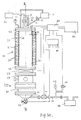
- Fig. 1a is a general schematic view of the spray drying system showing its main components and a block-diagram illustrating its functions.
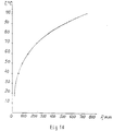
- Fig. 1b shows a pressure-temperature relationship which corresponds to liquid-vapour equilibrium transition for water, implemented in the spray drying system, according to the present invention.
- Figs. 2a,b show a different disposition of the atomizing means with respect to the longitudinal axis of the heating chamber.
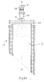
- Fig. 3 presents a diagrammatic view of the spray drying system equipped with moisture vapour sweeping means and an additional collection and recovery means.
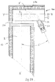
- Figs. 4a,b show an enlarged view of detail I encircled in Fig. 3 and enlarged partial view of the vapour sweeping means shown in Fig. 3.
- the system comprises feeding means 1, which supplies liquid material into interior 2 of the heating chamber 10 in which evaporation of the liquid takes place.
- the feeding means is substantially formed as a closed container equipped with a pump (not shown) for direct supply of the feed to the heating chamber through the appropriate piping line or to atomization means 5 by gravitation via a slanted pipe line 4.
- the feeding means 1 might be provided with the appropriate heating or cooling device and/or agitator so as to control the temperature inside the container and to adjust viscosity of the feed before it is supplied to the chamber.
- Piping line 4 might be provided with a regulating valve 6, mounted adjacent to the outlet opening of the container so as to enable control of the feed rate to the liquid material being supplied to atomization means 5.
- Liquid material after it is atomized is dried inside the main heating chamber 10, which is preferably formed as a cylinder with longitudinal axis X-X.
- the hollow interior 2 of the chamber is defined by inner wall 20, upper flange 22 and lower flange 24.
- the interior of the heating chamber is divided into the upper extremity 21, situated adjacent to the atomization means 5, central heating zone and lower extremity 23, which communicates via sliding gate 25 with dry collecting means 26.
- the heating chamber is provided with heating elements, preferably formed as a spiral 27, coiled around the outwardly facing surface of cylindrical wall 20.
- the heating elements are connected with the appropriate power supply (not shown) so as to provide indirect heating of dried material inside the heating chamber by means of heat transfer via chamber wall 20.
- heating elements along the entire length of the cylindrical wall of the chamber and divide them into groups so as to provide independent local heating of different zones of the heating chamber along its longitudinal axis X-X.
- An insulation layer 28 closes heating spiral 27 so as to prevent loss of heat to the outside.
- spiral heating elements instead of spiral heating elements, an alternative means, suitable for indirect heating, can be provided, e.g., infrared heaters, steam-heated jacket, etc.
- the inner wall of the heating chamber is made from appropriate heat-resistant material, e.g., stainless steel, glass, refractory ceramic or their combination.
- the atomizing means 5, employed in the drying system, according to the present invention, is preferably formed as an ultrasonic oscillator 50 which is connected to a generator of ultrasonic vibrations 51. It is preferably that the oscillator be joined with a nozzle tip.
- the feed which was initially presented in continuous liquid form, becomes a spray which consists of a plurality of tiny discrete droplets constituting a mist, characterized by a very large surface.
- Oscillator 50 is provided with an elongated horn portion 52 which submits a vibratory motion at its free end 53 to the liquid material supplied to the nozzle by said feeding means.
- Fig. 1a shows the supply of liquid feed to the free end of the nozzle from the outside container by means of piping line 4; however, it should be understood that the feed can be supplied to the free end of the horn portion via the through-going passageway formed in the oscillator itself as well.
- Oscillator 50 can also be provided with an appropriate polarization means which submits an electrostatic charge to the spray droplets, thus enabling better control of spray pattern geometry.
- Arrangement of polarization means as well as appropriate means for its control can be carried out according to known techniques e.g., as described in Rudenko's Russian patent SU 978934 or PCT application US87/02159.
- Figs. 1a and 2a show the coaxial disposition of the spray nozzle 50 with respect to the longitudinal axis X-X. By virtue of this disposition the geometric spray pattern achieved is schematically shown by the dotted lines in Fig. 2a.
- oscillator 50 is situated inside the auxiliary heating compartment 100 located at the upper end of the main heating chamber 10.
- Compartment 100 extends radially with respect to the main heating chamber; its interior 2' communicates with the interior 2 of the main heating chamber by means of neck portion 150.
- the auxiliary compartment 100 might be provided with heating elements 270 mounted outside its interior 2' so as to enable indirect initial heating of the atomized spray, before it reaches heating chamber 10.
- oscillator 50 is slanted with respect to the longitudinal axis X-X of the main heating chamber in the sense that the elongated horn portion 52 of the nozzle tip defines a certain acute angle ⁇ with this axis.
- the spray coming out of the ultrasonic oscillator is atomized into fine droplets, their size varying between 10 and 100 microns depending on the power supplied by the generator to the oscillator.
- This spray enters the auxiliary heating compartment and after that proceeds downward into the main heating chamber.
- the geometry of the spray associated with this arrangement is shown by the dotted lines in Fig. 2b. It can be easily understood that by changing the angle ⁇ , this geometry can be varied so as to ensure the most efficient spraying of feeds, the initial liquid condition of which is characterized by different viscosities.
- ultrasonic oscillation is not the only suitable method for atomizing liquid feed; alternative embodiments of the atomizing means can be employed in the drying system according to the present invention, e.g., a spinning disc centrifugal atomizer.
- the method of employing two fluid spray atomizers can be used as well.
- Atomized spray in the form of a mist is heated inside the heating chamber, and the fluid media is evaporated from the mist droplets while the dried solid particles of the final product, with desired residual moisture, fall down from the mist towards the bottom extremity 23 of the heating chamber. They are discharged with the collecting means 26, situated adjacent to the bottom extremity of the heating chamber.
- the collecting means is arranged at a considerable distance from the atomizing means so as to ensure sufficient residence time for the product moving from the heating zone to discharge zone.
- a suitable collecting means one can use a removable fabric bag filter arranged on a bag house (not shown), cyclone filter or their combination.
- sliding gate 25 is closed so as to evacuate interior 2 of the heating chamber from the collecting means.
- the fluid media evaporated from the liquid material is driven off by virtue of an appropriate evacuation means as will be explained later.
- This media in the form of a hot moist vapour, proceeds via the collecting means 26 into the recovery means 31, where it is transferred back to the liquid state and can be taken out of the system via outlet valve 32 which is installed in the conical bottom part of the recovery means. It might be advantageous to combine components 25, 26 and 31 into one modular unit 250 which will enable both product collection and recovery of the liquid media.
- a condenser with liquid cooling agent, or wet scrubber is an example of an appropriate recovery means which can be employed in the drying system, according to the present invention.
- the bottom part of the recovery means is provided with outlet port 33, communicating via valve V1 and piping line 34 with evacuation means 40.
- evacuation means to maintain reduced pressure inside the heating chamber and to exhaust the moisture vapour generated during evaporation of the fluid media, which was not recovered inside the recovery means.
- Liquid-vapour equilibria transition is implemented in the present invention, and by means of reduced pressure maintained in the chamber, drying heat sensitive materials becomes possible without deterioration of their properties, since evaporation of the liquid solvent takes place at reduced temperatures.
- Output capacity of evacuation means and level of reduced pressure inside the system can be adjusted by regulating valves V1,V2, installed correspondingly in piping line 34 and adjacent to pressure gauge 42.
- Pressure gauge 41 is arranged in the upper flange of the chamber so as to enable measuring the level of reduced pressure maintained in the chamber; pressure gauge 42 checks the pressure in piping line 34.
- the system has other relevant instrumentation which is required for its proper functioning, in particular, with contact thermometers and thermocouples for measuring temperatures in the feeding container, at the nozzle, in different zones of the heating chamber, and inside the collecting and recovery means.
- a computer control system 60 connected to outputs of all instrumentation items via interface 61.
- the computer system is also wired to the ultrasonic vibrations generator 51, the regulating valves V1, V2 and with the central instrument display panel 62, which is equipped with a switchboard, enabling coordinated control of the functioning of the system components.
- the system has been successfully employed for drying different kinds of heat-sensitive materials, in particular a pasty foodstuff with moisture content of 60-80%, a liquid detergent, and an emulsion of an organic adhesive.
- the feed in its initial liquid state was supplied from a container, the temperature of which was 20-30 °C; feed rate was in the range of 5-10 l/h.
- the feed was atomized, by means of an ultrasonic oscillator with nozzle tip, into fine droplets with a diameter of 30-70 microns and dried at a reduced pressure of 100 torr at 50 °C.
- the pump output of 10 l/sec was enough to maintain the required level of reduced pressure.
- the dried product in powder form, at 10 microns particle size and with negligible residual moisture content, was collected in the bag collector.
- this embodiment comprises basically similar components.
- the feed is supplied from container 1 by means of a feed pump (not shown) via piping line 4, directly towards the horn portion of the ultrasonic oscillator 50, which receives ultrasonic vibrations from the generator 51.
- the atomized spray is accelerated by the nozzle, enters the auxiliary heating compartment 100 and then proceeds further into the heating chamber 10.
- the bottom portion of the chamber communicates via the sliding gate with collecting and recovery means.
- An evacuation means 40 maintains the required level of reduced pressure inside the chamber.
- the vapour generated during evaporation of the fluid media is exhausted from the bottom extremity of the chamber by virtue of the same evacuation means 40, driving it off via piping line 34.
- At least one hollow tubular element 80 is mounted close to the cylindrical wall 20 of the heating chamber. As shown in Fig. 4a it is substantially formed as a closed tube extending along the wall and provided with a plurality of openings 81, which enable communication of the interior of the heating chamber with the interior of the tube.
- the tube is manufactured from a heat resistant material capable of withstanding working temperatures, developed in the heating chamber and extending outside of the chamber via the appropriate outlet port, arranged adjacent to the bottom extremity 23 of the chamber.
- the outside end of the tube is connected with a collecting and recovery modular unit 250', formed similarly to modular unit 250 and comprising sliding gate 25', collecting means 26', and condenser 31'.
- the outlet port 33' connects unit 250' with evacuation means 40 via regulating valve 34' and piping line 34 so as to provide reduced pressure inside the tubular element, sweeping off part of the vapour generated during evaporation of the spray.
- the purpose of the openings in the tubular element is to arrange for sweeping off of the vapour in a tangential direction along the entire length of the drying chamber.
- the size and geometry of these openings as well as the cross-sectional configuration of the tubular element is chosen so as to ensure efficient driving off of the vapour produced at every step of the drying process and in every zone of the chamber.
- the main part of the vapour moving in longitudinal direction and driven off via the bottom part of the chamber, moves more slowly, and therefore it becomes possible to increase residence time of material in the drying chamber and to ensure achieving the desired residual moisture content.
- the regulating valve 34' is connected with the control means 60 so as to provide coordinated functioning of sweeping means 80 with additional components of the drying system.
- the tubular elements 80 might be provided with shields 82, mounted adjacent to openings 81.
- the purpose of these shields is to direct the driven-off vapour along the trajectory shown by arrows in Fig. 4a towards openings 81, and to ensure that most of the dried particles become separated from the vapour and move towards the bottom extremity of the heating chamber.
Landscapes
- Engineering & Computer Science (AREA)
- Chemical & Material Sciences (AREA)
- Chemical Kinetics & Catalysis (AREA)
- Life Sciences & Earth Sciences (AREA)
- Mechanical Engineering (AREA)
- General Engineering & Computer Science (AREA)
- Health & Medical Sciences (AREA)
- Molecular Biology (AREA)
- Microbiology (AREA)
- Drying Of Solid Materials (AREA)
- Vaporization, Distillation, Condensation, Sublimation, And Cold Traps (AREA)
Applications Claiming Priority (2)
| Application Number | Priority Date | Filing Date | Title |
|---|---|---|---|
| IL10565893 | 1993-05-11 | ||
| IL10565893A IL105658A (en) | 1993-05-11 | 1993-05-11 | Spray drying system |
Publications (2)
| Publication Number | Publication Date |
|---|---|
| EP0628331A1 true EP0628331A1 (de) | 1994-12-14 |
| EP0628331B1 EP0628331B1 (de) | 1999-08-11 |
Family
ID=11064827
Family Applications (1)
| Application Number | Title | Priority Date | Filing Date |
|---|---|---|---|
| EP94302837A Expired - Lifetime EP0628331B1 (de) | 1993-05-11 | 1994-04-21 | Sprühtrocknungssystem |
Country Status (5)
| Country | Link |
|---|---|
| US (1) | US5624530A (de) |
| EP (1) | EP0628331B1 (de) |
| DE (1) | DE69419974T2 (de) |
| DK (1) | DK0628331T3 (de) |
| IL (1) | IL105658A (de) |
Cited By (10)
| Publication number | Priority date | Publication date | Assignee | Title |
|---|---|---|---|---|
| WO2001010526A1 (en) * | 1999-08-05 | 2001-02-15 | U.S. Aquasonics Corporation | Method and apparatus for economical solid-liquid separation in water-based solutions |
| WO2002073108A1 (de) * | 2001-03-12 | 2002-09-19 | Bionorica Ag | Verfahren zur schonenden gewinnung von trockenextrakten |
| WO2006120117A1 (en) * | 2005-05-13 | 2006-11-16 | Degussa Gmbh | Reactor and method for gentle product drying |
| US7994197B2 (en) | 2007-02-11 | 2011-08-09 | Map Pharmaceuticals, Inc. | Method of therapeutic administration of DHE to enable rapid relief of migraine while minimizing side effect profile |
| WO2015063090A3 (en) * | 2013-10-28 | 2015-10-22 | Chr. Hansen A/S | Drying of microorganisms |
| ES2601932A1 (es) * | 2017-01-11 | 2017-02-16 | Universidade De Santiago De Compostela | Dispositivo y procedimiento para la obtención de un producto desecado a partir de sangre o derivados |
| US9616060B2 (en) | 2002-04-17 | 2017-04-11 | Nektar Therapeutics | Particulate materials |
| US9700529B2 (en) | 2002-05-03 | 2017-07-11 | Nektar Therapeutics | Particulate materials |
| US9808030B2 (en) | 2011-02-11 | 2017-11-07 | Grain Processing Corporation | Salt composition |
| US10798955B2 (en) | 2000-11-09 | 2020-10-13 | Nektar Therapeutics | Compositions of particulate coformulation |
Families Citing this family (40)
| Publication number | Priority date | Publication date | Assignee | Title |
|---|---|---|---|---|
| US6051256A (en) * | 1994-03-07 | 2000-04-18 | Inhale Therapeutic Systems | Dispersible macromolecule compositions and methods for their preparation and use |
| US20030203036A1 (en) * | 2000-03-17 | 2003-10-30 | Gordon Marc S. | Systems and processes for spray drying hydrophobic drugs with hydrophilic excipients |
| JP2003510550A (ja) * | 1999-09-30 | 2003-03-18 | サイテック ソチエタ ア レスポンサビリタ リミタタ | 液体混合物を冷却し、液体混合物の状態の変更を行う方法および装置 |
| US7435317B2 (en) * | 2000-03-31 | 2008-10-14 | Biomass Conversions, L.L.C. | Desalination of ocean water |
| US7575761B2 (en) * | 2000-06-30 | 2009-08-18 | Novartis Pharma Ag | Spray drying process control of drying kinetics |
| KR100951750B1 (ko) * | 2001-11-01 | 2010-04-09 | 노바르티스 아게 | 분무 건조 방법 및 그 조성물 |
| US7582284B2 (en) | 2002-04-17 | 2009-09-01 | Nektar Therapeutics | Particulate materials |
| GB0216562D0 (en) | 2002-04-25 | 2002-08-28 | Bradford Particle Design Ltd | Particulate materials |
| GB0219815D0 (en) * | 2002-08-24 | 2002-10-02 | Accentus Plc | Preparation of small crystals |
| DE10234165B4 (de) * | 2002-07-26 | 2008-01-03 | Advanced Micro Devices, Inc., Sunnyvale | Verfahren zum Füllen eines Grabens, der in einem Substrat gebildet ist, mit einem isolierenden Material |
| CA2508870C (en) | 2002-12-30 | 2012-10-16 | Novartis Ag | Prefilming atomizer |
| DE102008040006A1 (de) * | 2008-08-27 | 2010-03-04 | Qvf Engineering Gmbh | Verdampfervorrichung und Batch-Destillationsverfahren |
| ES2684130T3 (es) | 2009-04-09 | 2018-10-01 | Entegrion, Inc. | Productos de la sangre secados por aspersión y métodos para elaborar los mismos |
| US20110142885A1 (en) | 2009-09-16 | 2011-06-16 | Velico Medical, Inc. | Spray-dried human plasma |
| US8715402B2 (en) * | 2011-03-22 | 2014-05-06 | Mitsubishi Heavy Industries, Ltd. | Air pollution control system and air pollution control method, spray drying device of dewatering filtration fluid from desulfurization discharged water, and method thereof |
| JP2012200657A (ja) * | 2011-03-24 | 2012-10-22 | Mitsubishi Heavy Ind Ltd | 脱硫排液からの脱水濾液の噴霧乾燥装置、排ガス処理システム及び方法 |
| NZ702870A (en) | 2012-06-22 | 2017-12-22 | Suganit Systems Inc | Method and apparatus for treatment of biomass substrates |
| IN2013CH04500A (de) | 2013-10-04 | 2015-04-10 | Kennametal India Ltd | |
| KR102394108B1 (ko) * | 2014-05-23 | 2022-05-03 | 더 뱁콕 앤드 윌콕스 컴퍼니 | 하나 이상의 장치로부터 액체 배출을 줄이기 위한 시스템 및 방법 |
| US9561184B2 (en) | 2014-09-19 | 2017-02-07 | Velico Medical, Inc. | Methods and systems for multi-stage drying of plasma |
| US10421030B2 (en) * | 2015-04-11 | 2019-09-24 | David Bradley Boylan | System and method for distillation |
| AR106558A1 (es) * | 2015-11-03 | 2018-01-24 | Spraying Systems Co | Aparato y método de secado por pulverización |
| DE102017102716A1 (de) | 2017-02-10 | 2018-08-16 | Lübbers Anlagen- und Umwelttechnik GmbH | Sprühdüse zum Versprühen eines zu trocknenden Gutes, Sprühtrockner und Verfahren zum Überwachen und/oder Steuern und/oder Regeln einer Temperatur beim Versprühen |
| CN107510600A (zh) * | 2017-08-07 | 2017-12-26 | 苏州大学 | 一种制备药用固体微粒的设备及方法 |
| US10933343B2 (en) * | 2017-10-27 | 2021-03-02 | Spraying Systems Co. | Spray dryer system and method |
| KR20230095075A (ko) * | 2020-10-27 | 2023-06-28 | 베스텔 일렉트로닉 사나이 베 티카레트 에이에스 | 아이템 건조 장치 및 아이템 건조 방법 |
| CN113945070B (zh) * | 2021-10-09 | 2022-09-27 | 无锡赫普轻工设备技术有限公司 | 一种微量化纳米粉体快速干燥及收集装置 |
| JP7367240B1 (ja) * | 2022-05-19 | 2023-10-23 | 株式会社神鋼環境ソリューション | 粒子製造装置および凍結粒子の製造方法 |
| CN115121190B (zh) * | 2022-06-16 | 2024-04-26 | 中国恩菲工程技术有限公司 | 一种超细粉体制备装置和方法 |
| US11841189B1 (en) | 2022-09-15 | 2023-12-12 | Velico Medical, Inc. | Disposable for a spray drying system |
| US12539355B2 (en) * | 2022-09-15 | 2026-02-03 | Velico Medical, Inc. | Dryer for a spray drying system |
| WO2024059770A1 (en) | 2022-09-15 | 2024-03-21 | Velico Medical, Inc. | Rapid spray drying system |
| US11998861B2 (en) | 2022-09-15 | 2024-06-04 | Velico Medical, Inc. | Usability of a disposable for a spray drying plasma system |
| US12083447B2 (en) | 2022-09-15 | 2024-09-10 | Velico Medical, Inc. | Alignment of a disposable for a spray drying plasma system |
| US12571587B2 (en) * | 2022-09-15 | 2026-03-10 | Velico Medical, Inc. | Finishing apparatus for a spray drying system |
| US12246093B2 (en) | 2022-09-15 | 2025-03-11 | Velico Medical, Inc. | Methods for making spray dried plasma |
| US12246266B2 (en) | 2022-09-15 | 2025-03-11 | Velico Medical, Inc. | Disposable for a spray drying system |
| US11975274B2 (en) | 2022-09-15 | 2024-05-07 | Velico Medical, Inc. | Blood plasma product |
| CN116077955A (zh) * | 2022-12-01 | 2023-05-09 | 攀枝花攀钢集团设计研究院有限公司 | 一种四氯化钛矿浆的蒸发处理装置 |
| GB202402626D0 (en) * | 2024-02-23 | 2024-04-10 | Ttp Plc | Spray freeze drying formation of dry powder compositions |
Citations (3)
| Publication number | Priority date | Publication date | Assignee | Title |
|---|---|---|---|---|
| JPS5834002A (ja) * | 1981-08-24 | 1983-02-28 | Ichiro Tsutsui | 超音波噴霧乾燥法 |
| DE3409815A1 (de) * | 1984-03-16 | 1985-09-26 | Siemens AG, 1000 Berlin und 8000 München | Porositaet aufweisende gesinterte oxidkeramik und daraus hergestellte wandler |
| WO1988001540A1 (en) * | 1986-08-27 | 1988-03-10 | M & T Chemicals, Inc. | Internal shut-off assembly for ultrasonic dispersion nozzle |
Family Cites Families (15)
| Publication number | Priority date | Publication date | Assignee | Title |
|---|---|---|---|---|
| FR972367A (fr) * | 1941-02-19 | 1951-01-29 | Krebs & Co Ag | Procédé d'évaporation de solutions aqueuses ou autres, et installation pour la réalisation de ce procédé |
| CH353678A (de) * | 1957-06-12 | 1961-04-15 | Ciba Geigy | Verfahren zur Gewinnung eines Granulates bei der Zerstäubungstrocknung von flüssigen oder pastenförmigen Stoffen oder von Filterkuchen und Einrichtung zur Durchführung des Verfahrens |
| US3620776A (en) * | 1968-06-28 | 1971-11-16 | Nestle Sa | Spray drying process |
| US3922189A (en) * | 1971-09-13 | 1975-11-25 | Hubertus Carolus Marie Penders | Drying of liqueform materials |
| US4052255A (en) * | 1971-10-07 | 1977-10-04 | J. M. Huber Corporation | Spray dryer discharge system |
| US4141783A (en) * | 1972-08-29 | 1979-02-27 | Aktieselskabet Niro Atomizer | Spray drying atomizer wheel |
| SE426544B (sv) * | 1979-11-30 | 1983-01-31 | Alfa Laval Ab | Forfarande for utvinning av fiskmjol med hog proteinkvalitet och fiskolja |
| SU978934A1 (ru) * | 1981-03-24 | 1982-12-07 | Институт Прикладной Физики Ан Мсср | Устройство дл распылени жидких сред |
| JPS5813634A (ja) * | 1981-07-15 | 1983-01-26 | Matsushita Electric Works Ltd | 熱硬化性樹脂成形材料の製造方法 |
| US4421594A (en) * | 1981-08-24 | 1983-12-20 | Bildjukevich Viktor L | Method of and apparatus for producing granulated products from a suspension |
| US4412653A (en) * | 1981-10-02 | 1983-11-01 | Combustion Engineering, Inc. | Sonic atomizing spray nozzle |
| DE68915309T2 (de) * | 1988-03-04 | 1995-01-05 | Atomic Energy Authority Uk | Zerstäuber. |
| JPH02191501A (ja) * | 1989-01-20 | 1990-07-27 | Fuji Photo Film Co Ltd | 真空濃縮乾燥方法 |
| US5015382A (en) * | 1989-04-20 | 1991-05-14 | E. I. Du Pont De Nemours And Company | Microporous support layer with interfacially polymerized copolyamide membrane thereon |
| DE69229914T2 (de) * | 1991-05-21 | 2000-04-20 | Analytica Of Brandford, Inc. | Verfahren und Apparat zur Verbesserung der Sprühionisation von gelösten Stoffen |
-
1993
- 1993-05-11 IL IL10565893A patent/IL105658A/en not_active IP Right Cessation
-
1994
- 1994-04-21 DK DK94302837T patent/DK0628331T3/da active
- 1994-04-21 US US08/230,696 patent/US5624530A/en not_active Expired - Lifetime
- 1994-04-21 EP EP94302837A patent/EP0628331B1/de not_active Expired - Lifetime
- 1994-04-21 DE DE69419974T patent/DE69419974T2/de not_active Expired - Fee Related
Patent Citations (3)
| Publication number | Priority date | Publication date | Assignee | Title |
|---|---|---|---|---|
| JPS5834002A (ja) * | 1981-08-24 | 1983-02-28 | Ichiro Tsutsui | 超音波噴霧乾燥法 |
| DE3409815A1 (de) * | 1984-03-16 | 1985-09-26 | Siemens AG, 1000 Berlin und 8000 München | Porositaet aufweisende gesinterte oxidkeramik und daraus hergestellte wandler |
| WO1988001540A1 (en) * | 1986-08-27 | 1988-03-10 | M & T Chemicals, Inc. | Internal shut-off assembly for ultrasonic dispersion nozzle |
Non-Patent Citations (2)
| Title |
|---|
| CHEMICAL ENGINEERING, vol. 68, 4 September 1961 (1961-09-04), NY, pages 84-86 * |
| PATENT ABSTRACTS OF JAPAN vol. 7, no. 114 (C - 166)<1259> 18 May 1983 (1983-05-18) * |
Cited By (21)
| Publication number | Priority date | Publication date | Assignee | Title |
|---|---|---|---|---|
| US6299735B1 (en) | 1998-08-12 | 2001-10-09 | U.S. Aquasonics Corp. | Method for solid-liquid separation in water-based solutions |
| WO2001010526A1 (en) * | 1999-08-05 | 2001-02-15 | U.S. Aquasonics Corporation | Method and apparatus for economical solid-liquid separation in water-based solutions |
| US10798955B2 (en) | 2000-11-09 | 2020-10-13 | Nektar Therapeutics | Compositions of particulate coformulation |
| WO2002073108A1 (de) * | 2001-03-12 | 2002-09-19 | Bionorica Ag | Verfahren zur schonenden gewinnung von trockenextrakten |
| US6996919B2 (en) | 2001-03-12 | 2006-02-14 | Bionorica Ag | Process for obtaining dry extracts under mild conditions |
| US10251881B2 (en) | 2002-04-17 | 2019-04-09 | Nektar Therapeutics | Particulate materials |
| US9616060B2 (en) | 2002-04-17 | 2017-04-11 | Nektar Therapeutics | Particulate materials |
| US9700529B2 (en) | 2002-05-03 | 2017-07-11 | Nektar Therapeutics | Particulate materials |
| US10945972B2 (en) | 2002-05-03 | 2021-03-16 | Nektar Therapeutics | Particulate materials |
| US10188614B2 (en) | 2002-05-03 | 2019-01-29 | Nektar Therapeutics | Particulate materials |
| WO2006120117A1 (en) * | 2005-05-13 | 2006-11-16 | Degussa Gmbh | Reactor and method for gentle product drying |
| US7994197B2 (en) | 2007-02-11 | 2011-08-09 | Map Pharmaceuticals, Inc. | Method of therapeutic administration of DHE to enable rapid relief of migraine while minimizing side effect profile |
| US9833451B2 (en) | 2007-02-11 | 2017-12-05 | Map Pharmaceuticals, Inc. | Method of therapeutic administration of DHE to enable rapid relief of migraine while minimizing side effect profile |
| US10172853B2 (en) | 2007-02-11 | 2019-01-08 | Map Pharmaceuticals, Inc. | Method of therapeutic administration of DHE to enable rapid relief of migraine while minimizing side effect profile |
| US8148377B2 (en) | 2007-02-11 | 2012-04-03 | Map Pharmaceuticals, Inc. | Method of therapeutic administration of DHE to enable rapid relief of migraine while minimizing side effect profile |
| US8119639B2 (en) | 2007-02-11 | 2012-02-21 | Map Pharmaceuticals, Inc. | Method of therapeutic administration of DHE to enable rapid relief of migraine while minimizing side effect profile |
| US9808030B2 (en) | 2011-02-11 | 2017-11-07 | Grain Processing Corporation | Salt composition |
| WO2015063090A3 (en) * | 2013-10-28 | 2015-10-22 | Chr. Hansen A/S | Drying of microorganisms |
| US10745661B2 (en) | 2013-10-28 | 2020-08-18 | Chr. Hansen A/S | Drying of microorganisms |
| WO2018130736A1 (es) * | 2017-01-11 | 2018-07-19 | Universidade De Santiago De Compostela | Dispositivo y procedimiento para la obtención de un producto desecado a partir de sangre o derivados |
| ES2601932A1 (es) * | 2017-01-11 | 2017-02-16 | Universidade De Santiago De Compostela | Dispositivo y procedimiento para la obtención de un producto desecado a partir de sangre o derivados |
Also Published As
| Publication number | Publication date |
|---|---|
| DE69419974T2 (de) | 2000-03-09 |
| IL105658A (en) | 1995-10-31 |
| IL105658A0 (en) | 1993-09-22 |
| US5624530A (en) | 1997-04-29 |
| DE69419974D1 (de) | 1999-09-16 |
| DK0628331T3 (da) | 2000-03-20 |
| EP0628331B1 (de) | 1999-08-11 |
Similar Documents
| Publication | Publication Date | Title |
|---|---|---|
| US5624530A (en) | Spray drying system | |
| Filková et al. | 9 Industrial Spray Drying Systems | |
| CA2203599C (en) | Two-stage drying spray dryer | |
| US9788566B2 (en) | Process for drying and powderizing functional foods, nutraceuticals, and natural health ingredients | |
| US4052255A (en) | Spray dryer discharge system | |
| ES312609A1 (es) | Procedimiento para desecar sustancias sensibles al calor, y aparato para la realizacion del mismo | |
| US7628893B1 (en) | Apparatus and method for separation | |
| EP0961646A2 (de) | Methode und vorrichtung zur sprühtrocknung sowie reinigungsmethode für eine solche vorrichtung | |
| US20040145069A1 (en) | Nozzle valve type spray dryer | |
| US3246683A (en) | Preparing slurry mixtures of pulverous solids and water | |
| US4020564A (en) | Drier for temperature sensitive materials | |
| RU2166713C1 (ru) | Распылительная сушильная установка | |
| US5419814A (en) | Thin layer liquid film type evaporator | |
| US3191662A (en) | Continuous solution concentrator | |
| Bhandari | Spray drying and powder properties | |
| RU2267066C1 (ru) | Сушильная установка для получения порошков из жидких продуктов и способ сушки жидких продуктов | |
| GB2043474A (en) | Method and apparatus for drying a pumpable substance containing a liquid | |
| US3236285A (en) | Spray drying of liquids | |
| KR100329124B1 (ko) | 저압 노즐 분사식 분무건조 시스템 | |
| RU2125217C1 (ru) | Процесс и устройство для сушки или органических и/или неорганических материалов | |
| CN213466787U (zh) | 一种离心喷雾干燥机 | |
| US5615492A (en) | Drying of water-containing useful materials or mixtures thereof with superheated steam | |
| US3828837A (en) | Apparatus for evaporating liquid from a solution or suspension | |
| JPH02194812A (ja) | 廃ガス洗浄から残留物を除去する方法及び装置 | |
| SU1044912A2 (ru) | Вихрева распылительна сушилка |
Legal Events
| Date | Code | Title | Description |
|---|---|---|---|
| PUAI | Public reference made under article 153(3) epc to a published international application that has entered the european phase |
Free format text: ORIGINAL CODE: 0009012 |
|
| AK | Designated contracting states |
Kind code of ref document: A1 Designated state(s): DE DK ES FR GB IT |
|
| 17P | Request for examination filed |
Effective date: 19950519 |
|
| RAP3 | Party data changed (applicant data changed or rights of an application transferred) |
Owner name: ULTRASONIC DRYER LTD. |
|
| 17Q | First examination report despatched |
Effective date: 19970512 |
|
| GRAG | Despatch of communication of intention to grant |
Free format text: ORIGINAL CODE: EPIDOS AGRA |
|
| GRAG | Despatch of communication of intention to grant |
Free format text: ORIGINAL CODE: EPIDOS AGRA |
|
| GRAH | Despatch of communication of intention to grant a patent |
Free format text: ORIGINAL CODE: EPIDOS IGRA |
|
| GRAH | Despatch of communication of intention to grant a patent |
Free format text: ORIGINAL CODE: EPIDOS IGRA |
|
| GRAA | (expected) grant |
Free format text: ORIGINAL CODE: 0009210 |
|
| AK | Designated contracting states |
Kind code of ref document: B1 Designated state(s): DE DK ES FR GB IT |
|
| PG25 | Lapsed in a contracting state [announced via postgrant information from national office to epo] |
Ref country code: IT Free format text: LAPSE BECAUSE OF FAILURE TO SUBMIT A TRANSLATION OF THE DESCRIPTION OR TO PAY THE FEE WITHIN THE PRESCRIBED TIME-LIMIT;WARNING: LAPSES OF ITALIAN PATENTS WITH EFFECTIVE DATE BEFORE 2007 MAY HAVE OCCURRED AT ANY TIME BEFORE 2007. THE CORRECT EFFECTIVE DATE MAY BE DIFFERENT FROM THE ONE RECORDED. Effective date: 19990811 Ref country code: FR Free format text: LAPSE BECAUSE OF FAILURE TO SUBMIT A TRANSLATION OF THE DESCRIPTION OR TO PAY THE FEE WITHIN THE PRESCRIBED TIME-LIMIT Effective date: 19990811 Ref country code: ES Free format text: THE PATENT HAS BEEN ANNULLED BY A DECISION OF A NATIONAL AUTHORITY Effective date: 19990811 |
|
| REF | Corresponds to: |
Ref document number: 69419974 Country of ref document: DE Date of ref document: 19990916 |
|
| EN | Fr: translation not filed | ||
| REG | Reference to a national code |
Ref country code: DK Ref legal event code: T3 |
|
| PLBE | No opposition filed within time limit |
Free format text: ORIGINAL CODE: 0009261 |
|
| STAA | Information on the status of an ep patent application or granted ep patent |
Free format text: STATUS: NO OPPOSITION FILED WITHIN TIME LIMIT |
|
| 26N | No opposition filed | ||
| REG | Reference to a national code |
Ref country code: GB Ref legal event code: IF02 |
|
| PGFP | Annual fee paid to national office [announced via postgrant information from national office to epo] |
Ref country code: DK Payment date: 20020411 Year of fee payment: 9 |
|
| PGFP | Annual fee paid to national office [announced via postgrant information from national office to epo] |
Ref country code: GB Payment date: 20020417 Year of fee payment: 9 |
|
| PGFP | Annual fee paid to national office [announced via postgrant information from national office to epo] |
Ref country code: DE Payment date: 20020424 Year of fee payment: 9 |
|
| PG25 | Lapsed in a contracting state [announced via postgrant information from national office to epo] |
Ref country code: GB Free format text: LAPSE BECAUSE OF NON-PAYMENT OF DUE FEES Effective date: 20030421 |
|
| PG25 | Lapsed in a contracting state [announced via postgrant information from national office to epo] |
Ref country code: DK Free format text: LAPSE BECAUSE OF NON-PAYMENT OF DUE FEES Effective date: 20030430 |
|
| PG25 | Lapsed in a contracting state [announced via postgrant information from national office to epo] |
Ref country code: DE Free format text: LAPSE BECAUSE OF NON-PAYMENT OF DUE FEES Effective date: 20031101 |
|
| REG | Reference to a national code |
Ref country code: DK Ref legal event code: EBP |
|
| GBPC | Gb: european patent ceased through non-payment of renewal fee |
Effective date: 20030421 |