EP0627904B1 - Instrument pour microchirurgie avec un embout d'aspiration flexible et orientable - Google Patents
Instrument pour microchirurgie avec un embout d'aspiration flexible et orientable Download PDFInfo
- Publication number
- EP0627904B1 EP0627904B1 EP93904798A EP93904798A EP0627904B1 EP 0627904 B1 EP0627904 B1 EP 0627904B1 EP 93904798 A EP93904798 A EP 93904798A EP 93904798 A EP93904798 A EP 93904798A EP 0627904 B1 EP0627904 B1 EP 0627904B1
- Authority
- EP
- European Patent Office
- Prior art keywords
- tip
- aspiration
- sleeve
- flexible
- aspiration tip
- Prior art date
- Legal status (The legal status is an assumption and is not a legal conclusion. Google has not performed a legal analysis and makes no representation as to the accuracy of the status listed.)
- Expired - Lifetime
Links
Images


Classifications
-
- A—HUMAN NECESSITIES
- A61—MEDICAL OR VETERINARY SCIENCE; HYGIENE
- A61M—DEVICES FOR INTRODUCING MEDIA INTO, OR ONTO, THE BODY; DEVICES FOR TRANSDUCING BODY MEDIA OR FOR TAKING MEDIA FROM THE BODY; DEVICES FOR PRODUCING OR ENDING SLEEP OR STUPOR
- A61M1/00—Suction or pumping devices for medical purposes; Devices for carrying-off, for treatment of, or for carrying-over, body-liquids; Drainage systems
- A61M1/84—Drainage tubes; Aspiration tips
-
- A—HUMAN NECESSITIES
- A61—MEDICAL OR VETERINARY SCIENCE; HYGIENE
- A61F—FILTERS IMPLANTABLE INTO BLOOD VESSELS; PROSTHESES; DEVICES PROVIDING PATENCY TO, OR PREVENTING COLLAPSING OF, TUBULAR STRUCTURES OF THE BODY, e.g. STENTS; ORTHOPAEDIC, NURSING OR CONTRACEPTIVE DEVICES; FOMENTATION; TREATMENT OR PROTECTION OF EYES OR EARS; BANDAGES, DRESSINGS OR ABSORBENT PADS; FIRST-AID KITS
- A61F9/00—Methods or devices for treatment of the eyes; Devices for putting-in contact lenses; Devices to correct squinting; Apparatus to guide the blind; Protective devices for the eyes, carried on the body or in the hand
- A61F9/007—Methods or devices for eye surgery
- A61F9/00736—Instruments for removal of intra-ocular material or intra-ocular injection, e.g. cataract instruments
-
- A—HUMAN NECESSITIES
- A61—MEDICAL OR VETERINARY SCIENCE; HYGIENE
- A61B—DIAGNOSIS; SURGERY; IDENTIFICATION
- A61B17/00—Surgical instruments, devices or methods, e.g. tourniquets
- A61B17/00234—Surgical instruments, devices or methods, e.g. tourniquets for minimally invasive surgery
- A61B2017/00292—Surgical instruments, devices or methods, e.g. tourniquets for minimally invasive surgery mounted on or guided by flexible, e.g. catheter-like, means
- A61B2017/003—Steerable
- A61B2017/00318—Steering mechanisms
- A61B2017/00331—Steering mechanisms with preformed bends
-
- A—HUMAN NECESSITIES
- A61—MEDICAL OR VETERINARY SCIENCE; HYGIENE
- A61M—DEVICES FOR INTRODUCING MEDIA INTO, OR ONTO, THE BODY; DEVICES FOR TRANSDUCING BODY MEDIA OR FOR TAKING MEDIA FROM THE BODY; DEVICES FOR PRODUCING OR ENDING SLEEP OR STUPOR
- A61M2205/00—General characteristics of the apparatus
- A61M2205/10—General characteristics of the apparatus with powered movement mechanisms
- A61M2205/106—General characteristics of the apparatus with powered movement mechanisms reciprocating
-
- Y—GENERAL TAGGING OF NEW TECHNOLOGICAL DEVELOPMENTS; GENERAL TAGGING OF CROSS-SECTIONAL TECHNOLOGIES SPANNING OVER SEVERAL SECTIONS OF THE IPC; TECHNICAL SUBJECTS COVERED BY FORMER USPC CROSS-REFERENCE ART COLLECTIONS [XRACs] AND DIGESTS
- Y10—TECHNICAL SUBJECTS COVERED BY FORMER USPC
- Y10S—TECHNICAL SUBJECTS COVERED BY FORMER USPC CROSS-REFERENCE ART COLLECTIONS [XRACs] AND DIGESTS
- Y10S604/00—Surgery
- Y10S604/902—Suction wands
Definitions
- the present invention is directed to handpiece for use in microsurgery having a flexible and steerable aspiration tip.
- the flexible and steerable aspiration tip includes a flexible tip portion, the shape of which may be remotely altered to permit the tip portion to access difficult to reach areas while performing a variety of surgical procedures.
- the flexible and steerable aspiration tip is especially adapted for microsurgical procedures in the field of surgery, such as ophthalmic surgery including cataract extraction and neuro- or ear surgery.
- US-A-4,169,984 to Parisi discloses an ultrasonic probe assembly for use in surgical procedures.
- the ultrasonic probe includes an angled tip portion as best seen in Figure 2.
- the tip of Parisi does not include structure to permit movement thereof during surgical procedures.
- US-A-4,210,146 to Banko discloses a surgical instrument with a bendable blade.
- the blade is designed to move with respect to an opening in the instrument tip to make a shearing action to cut tissue which enters the opening.
- the blade is formed in a manner so that, as it reciprocates into a tapered portion of the distal end tube, it will bend to conform to the shape of the tapered portion of the tube to provide continuous contact and improve cutting action.
- the surgical instrument of Banko does not teach or suggest a flexible tip, the shape of which may be remotely altered to access different surgical sites.
- US-A-4,459,509 to Auth discloses a rotating cutting tool having spirally shaped cutting flutes with different cutting properties.
- the tool is driven from outside the tool body by means of a flexible drive shaft.
- the tool of Auth is designed to be inserted into a human vascular network to remove plaque deposits.
- US-A-4,473,077 to noisy et al. discloses a surgical stapler apparatus having a flexible shaft.
- the apparatus includes structure which greatly reduces or essentially eliminates the tendency of the shaft assembly to revert to its straight condition during transmittal of longitudinal forces during stapling.
- US-A-4,672,964 to Dee et al. discloses a scalpel having a universally adjustable blade mounted to the scalpel handle for selective positioning.
- the scalpel includes structure which permits rotation of the blade about the axis of the handle as well as angular positioning with respect thereto.
- the scalpel assembly does not include means which permits flexing or bending of the scalpel or scalpel assembly during use.
- US-A-3,847,154 to Nordin discloses a surgical drill having an angular housing which is particularly useful where it is desired to reach very inaccessible areas in the body during a sensitive operation.
- the angular housing of the surgical drill disclosed in the Nordin patent is not flexible or adjustable.
- AU-B-57321 to Pericic discloses an oscillating surgical knife which has specific applications to eye surgery.
- the oscillating surgical knife in one embodiment, includes a chuck which permits angular displacement of the blade in the direction of oscillation thereby allowing the blade to be located at angles to enable the blade to reach a position which may otherwise be difficult or impossible.
- the oscillating surgical knife of Pericic does not include structure of means to permit the knife to be flexibly steered to access difficult to reach areas.
- US-A-5,084,012 discloses an irrigation and aspiration instrument having a curved aspiration tip, in which the aspiration tip remains fixed, and is straightened by manually sliding a rigid infusion sleeve separate from the handpiece over a flexible curved portion of the tip.
- EP-A-0,316,085 discloses a surgical cutting instrument, in which a cutting tip is reciprocated rapidly within a rigid probe or sleeve, providing a shearing, chopping action.
- the aspirating function is provided by suction and an irrigation function is provided by an irrigation fluid passageway between the sleeve and the tip.
- the tip in EP-A-0,316,085 is rigid, not flexible, and does not address the problem of aspirating difficult to access areas of a surgical site.
- cataract surgery In the field of cataract surgery, the goal of the surgery is the removal and anatomical replacement of an original, clouded lens with an optically clear intraocular lens using a small incision as well as a minimum of trauma to the surgical site.
- Current techniques being used to effect cataract surgery include extra capsular cataract extraction (ECCE) or endocapsular phacoemulsification (ECPE).
- ECCE extra capsular cataract extraction
- ECPE endocapsular phacoemulsification
- a small gauge irrigation/aspiration tip is used to remove any residual cortex and epithelium adjacent the capsular bag.
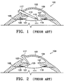
- Figure 1 illustrates a sectional view of an eye 100 including a cornea 103, sclera 105, iris 107 and capsular bag 111.
- a straight and rigid irrigation/aspiration instrument 113 having a tip portion 115 is inserted into the eye through the limbal incision 117.
- Peripheral cortex is easily engaged by the irrigation/aspiration tip 115 at the location directly opposite the incision designated by reference numeral 119.
- the cortex directly under the iris 107 directly below the incision 121 is difficult to access when using a straight and rigid irrigation/aspiration tip.
- irrigation/aspiration tips have been proposed having an angled or bent configuration.
- an irrigation/aspiration tip 123 is shown inserted through the limbal incision 117 and including an angled tip portion 125.
- cortex may be easily removed from the 12 o'clock position 121.
- engagement and removal of cortex directly under the iris at the 6 o'clock position 119 becomes difficult using the angled tip 125.
- both the straight and rigid irrigation/aspiration tip 113 and the angled tip 123 must be used during the surgical procedure.
- Using both surgical instruments requires removal of one followed by insertion of the other which results in additional trauma to the surrounding ocular tissue during the surgical operation as well as requiring additional items for each surgical procedure with the attendant sterilization, cleanliness and assembly requirements.
- the present invention provides a handpiece for use in microsurgery having a flexible and steerable aspiration tip, in particular, ophthalmic surgery such as cataract removal.
- the flexible and steerable aspiration tip includes a flexible tip portion, the shape of which may be remotely altered to permit the tip portion to access difficult to reach areas.
- the flexible and steerable aspiration tip permits performing a variety of surgical procedures while eliminating the requirement of using differently configured tips during the surgical procedure.
- any lenticular material for example, nuclear, capsular or cortical material
- the aspiration tip includes a straight rigid portion, a flexible free end and may include a spherical distal cap.
- the flexible free end further includes a pre-stressed activation spring coated by an elastomeric material, the spring having a curved shape in its relaxed state.
- the aspiration tip is connected to a handpiece assembly which includes a housing adapted to provide aspiration therethrough, a piston assembly and sleeve.
- the piston assembly and sleeve cooperate with the flexible portion to provide flexing and steering of the tip during a surgical or medical procedure such as cataract extraction.
- the aspiration tip is designed to removably attach to the handpiece and connect to the piston assembly.
- the piston assembly longitudinally translates the aspirating tip within the rigid sleeve.
- the energy of the activation spring is overcome such that the spring and flexible tip are configured in a straight and rigid manner.
- the aspiration tip is in a straight and rigid configuration for use in cataract surgery.
- the spring is permitted to return to its relaxed state such that the tip is configured in a curved manner to access difficult to reach areas in the surgical site.
- the sleeve is designed to engage an outer and distal end of the handpiece and includes a passageway to provide irrigation fluid to the surgical site.
- the sleeve includes a rigid tubular distal end which maintains the activation spring in its straight configuration when the piston assembly retracts the aspiration tip within the sleeve.
- a pull wire may be attached to the distal end of the flexible and steerable aspiration tip, the piston assembly providing the flexing and steering of the tip during a surgical or medical procedure such as cataract extraction.
- This embodiment allows the use of a soft, elastomeric sleeve to surround the flexible and steerable aspiration tip to provide for irrigation to the surgical site.
- the flexible and steerable aspiration tip is used without a sleeve.
- the present invention is concerned with handpiece for use in microsurgery having a flexible and steerable aspiration tip, particularly for use in surgical procedures in the field of ophthalmic surgery.
- the flexible and steerable aspiration tip offers advantages over prior art devices by eliminating the necessity of using a plurality of instruments to perform surgical procedures such as in, for example, cataract extraction.
- a single instrument to remove cortical lenticular tissue in a cataract extraction surgical procedure trauma to surrounding intraocular structures caused by withdrawal and reinsertion of a plurality of instruments is significantly reduced.
- the flexible and steerable aspiration tip permits removal of softened lenticular material without causing stress and possible consequent tearing and/or rupturing of lens capsules and/or zonules.
- the flexible and steerable tip has been disclosed for use in cataract extraction procedures, the flexible tip may be adapted for use as a bendable irrigating cannula or illuminator in ophthalmic surgical procedures involving the posterior segment of the eye as in vitreous and/or retinal surgery as well as in other microsurgical disciplines such as neuro- or ear surgery.
- the flexible and steerable aspiration tip is coupled with an irrigation/aspiration handpiece to permit manipulation of the aspiration tip at a surgical site as well as provide a means for remotely altering the configuration of the distal end of the flexible and steerable tip.
- the flexible and steerable aspiration tip is generally designated by the reference numeral 10 and is seen to include a rigid tubular member 1.
- the rigid tubular member 1 may be made out a suitable sized, stainless steel, thin-walled hypodermic tubing.
- the aspiration tip 10 also includes a flexible portion 3 which comprises an activation spring 5 covered by a thin layer of elastomeric material 7. Adjacent the distal end of the flexible portion 3 is a spherical distal cap 9 having an aperture 11 at the distal end thereof.
- the distal cap 9 is generally hollow and may be manufactured of stainless steel by progressive die or cold forming processes.
- the aperture 11 may be formed in the distal cap 9 by drilling, bead blasting or other known processes.
- the tubular member 1 and distal cap may be made from polymeric materials such as thermoplastics, e.g. ABS, polycarbonate, polypropylene or the like.
- the distal cap 9 includes a hollow male end 13 which is designed to be inserted within the spring 5 to couple the distal cap 9 to the flexible portion 3.
- the flexible portion 3 is coupled to the rigid tubular member 1 via the coupling 15.
- the coupling 15 is designed to receive the proximal end of the spring 5 and the distal end of the tubular member 1.
- the coupling 15 also includes a lip 16 designed to engage the distal end face 18 of the tubular member 1.
- the coupling 15 may also be made out of a stainless steel material.
- the spring 5, coupling 15 and tubular member 1 may be permanently joined by well known processes such as electrobeam welding.
- the tubular member 1 also includes a metal or plastic hub 17 having external threads 20 thereon.
- the hub 17 may be press fit or attached in other known manners to the tubular member 1.
- the hub is designed to facilitate attachment of the aspiration tip 10 to a suitable handpiece as will be discussed hereinafter.
- the thin elastomeric material 7 may be a polymer such as polyolefin or fluorosilicon.
- the elastomeric material 7 isolates the internal lumen 19 from the surrounding environment. Coating of the elastomeric material 7 on the spring 5 may be accomplished by a known processes such as injection insert molding, utilizing an internal mandrel in order to straighten the spring material during the overmolding process as well as keeping the lumen 19 of the aspiration tip open. The internal mandrel would be subsequently removed after the overmolding process completes coating of the spring material.
- Figure 5 shows a schematic representation of the spring 5 in both the pre-curved or relaxed state and the straight, stressed state.
- the curved or relaxed state is designated by the reference numeral 21 with the straight and stressed state designated by the reference numeral 25.
- the relaxed state 21 includes a defined radius designated by the reference numeral 23.
- the spring material includes on the distal end thereof a portion 27 having a length b. This straight portion 27 is designed to receive the distal cap 9 shown in cross-hatch.
- the activation spring 5 is manufactured from a material such as stainless steel wire in a relaxed state having the curve shown in Figure 5.
- a typical spring would include an outer diameter of 1 mm. (0.04 inches) and an overall length of 7.75 mm. (0.31 inches).
- a typical radius of curvature would be 1 mm. (0.04 inches) with the number of activation coils numbering 42 and the wire diameter as well as spacing between coils approximately 0.075 mm. (0.003 inches).
- the activation spring 5 may be straightened to the stressed state 25 by application of a force greater than the energy of the spring in the relaxed state 21.
- the handpiece 30 comprises a hollow housing 31 which is generally cylindrical in shape and of a length which approximates the length of a pencil to facilitate being held by a user.
- the housing 31 includes a bore 33 therein. Disposed within the bore 33 are an insert 35 and a length of rigid tubing 37.
- the insert 35 has an opening 39 which allows attachment of the aspiration tip 10 to the insert 35 by the hub 17 threadably engaging the internal threads (not shown) within the opening 39 of the insert.
- the rigid tube 37 may be integrally attached to the insert 35 so as to maintain the lumen passageway 19 along the lumen 49 within the rigid tubing 37.
- Other known coupling techniques may be utilized to provide removable attachment between the tip and handpiece components as well as between handpiece components, such press fitting, use of fasteners or the like.
- the distal end of the housing 31 of the handpiece 30 is designed to accept a cap 47.
- the cap 47 comprises a sleeve portion 51 which is designed to engage the outer surface of the housing 31 at the distal end thereof for attachment purposes.
- the cap 47 includes a thin-walled rigid sleeve 53.
- the thin-walled rigid sleeve may be of the type disclosed in US-A-4,787,899 to Steppe et al.
- the proximal end of the housing includes end cap 41 having ports 43 and 45.
- the housing 31 of the handpiece 30 includes a chamber 55 which contains a piston assembly 57.
- the piston assembly 57 includes a piston 59, a spring 61, bulkhead 63 and O-ring 65.
- the end cap 41 also includes an O-ring 67 at the distal end thereof.
- Figure 6 illustrates the handpiece 30 in a rest state with the flexible and steerable aspiration tip in a stressed state.
- the handpiece 30 is shown in the fully compressed state with the aspiration tip 10 shown in the fully relaxed state with the flexible portion in the curved position.
- pneumatic pressure is applied through the port 45 against the piston 59.
- the pneumatic pressure causes the piston 59 to move toward the distal end of the handpiece to compress the spring 61 against the bulkhead 63. Since the piston is attached to the tubular member 37, insert 35 and aspiration tip 10, longitudinal movement of the piston along the axis of the handpiece translates to longitudinal movement of the aspiration tip 10.
- O-rings 65 and 67 seal the chamber 69 between the piston 59 and the end cap 41 to permit application of pneumatic pressure against the piston.
- the cap 47 also includes a port 73 which may be used to supply irrigation fluid to the surgical site.
- the irrigation fluid would flow through the port 73 and between the aspiration tip 10 and inner circumference of the rigid sleeve 53 exiting at the distal end thereof.
- the distal end of the rigid sleeve 53 may have one or more apertures therein to facilitate flow of irrigation fluid therefrom.
- control unit is designed to control flow of irrigation fluid to the handpiece, aspiration from the handpiece, and application of pneumatic pressure by a user of the invention device. It should be understood that these types of control units are well recognized in the field of surgical aspiration and irrigation instrumentation and, therefore, are not described in greater detail.
- the aspiration tip 10 is depicted during a typical cortical clean-up phase of a planned extracapsular cataract extraction or phacoemulsification cataract surgery.
- the aspiration tip 10 and sleeve 53 are shown inserted through a limbal incision 75 and anterior capsulotomy 77 to remove cortical material 79 at the location designated by the reference numeral 81.
- the flexible and steerable aspiration tip is in the straight configuration to readily engage, strip the underlying cortex from the lens capsule 83, and aspirate removed material.
- pneumatic pressure is applied to the handpiece (not shown) to extend the flexible and steerable aspiration tip 10 from the confines of the sleeve 53 to achieve the curved configuration.
- the curved tip may access the cortical material at the location designated by the reference numeral 85.
- the surgical instrument is not required to be removed from the surgical site to access all cortical material in the lens capsule 83.
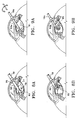
- Figures 9A and 9B illustrate another exemplary use of the flexible and steerable aspiration tip in a endocapsular cataract surgical procedure wherein a small anterior capsulotomy is performed such that the endocapsular bag remains essentially intact.
- Figures 9A and 9B also illustrate a flexible and steerable aspiration tip 10a and sleeve 53a of slightly smaller diameter than that disclosed in Figures 8A and 8B.
- lenticular material may be removed from both the location 81 as well as the location 85.
- Figure 9A also illustrates that the flexible and steerable aspiration tip 10a may be rotated to position the aperture in the distal cap of the flexible tip in a desired location.
- the flexible and steerable aspiration tip 10a can replace several instruments to perform the same surgical procedure and minimize trauma to the intraocular surgical site such as capsule tearing or zonular rupture.
- trauma to intraocular areas such as the iris or zonules are also minimized by using a single instrument having ready access to all capsular positions.
- the flexible portion 3' of the tip comprises a spring 5', which is similar to the spring disclosed in Figure 5, is provided with a pull wire 90 extending therethrough.
- the pull wire 90 is attached to the distal end of the spring 5' at reference numeral 92.
- the pull wire 90 extends through the lumen 19' and into the irrigation/aspiration handpiece as will be described hereinafter.
- the spring 5' includes a similar configuration as described for the spring 5 in Figure 5 and includes a relaxed state 21' and a stressed state 25'.
- the pull wire may be made of many materials and dimensions, with a preferred material being stainless steel and preferred dimensions including 0.05 mm. (0.002) inches by 0.15 mm. (0.006 inches).
- the pull wire 90 is attached to the distal end of the spring 5' using any known joining techniques such as soldering, welding or the like.
- an irrigation/aspiration handpiece is generally designated by the reference numeral 200 and seen to include a housing 201 having a shoulder 203 and a distal end portion of reduced diameter 205.
- the housing 201 includes a chamber 207 which houses a piston assembly 209.
- the piston assembly 209 includes a piston 210 having a reduced diameter neck portion 211 and a spring 213 designed to engage the neck portion 211 of the piston 210. Also provided is a sleeve 215 which is mounted in the proximal end of the piston 210. The sleeve 215 maintains a channel between the lumen 19' in the flexible and steerable aspiration tip 10' and the rigid tubular member l' and the aspiration port 217.
- the pull wire 90 is rigidly mounted to the piston 210.
- the flexible and steerable aspiration tip 10' may be configured between the straight and stressed state as depicted in Figure 11A and the relaxed and curved state depicted in Figure 11B.
- the piston 210 is under the force of the spring 213 thereby applying a force against the pull wire 90 and straightening the aspiration tip 10'.
- a pneumatic pressure is applied through the port 221 forcing the piston 210 to compress the spring 213 and relax the tension on the pull wire 90.
- the aspiration tip 10' is allowed to relax to its curved position.
- the flexible and steerable aspiration tip 10' may be configured in any position between the straight position depicted in Figure 11A and the fully curved position depicted in Figure 11B.
- a flexible sleeve 223 may be utilized in place of the rigid sleeve 53 disclosed in the embodiment depicted in Figures 6 and 7.
- the sleeve may be omitted using the pull wire embodiment.
- the distal end tip may include illumination means or utilized merely for irrigation purposes alone.
- the sleeve 53 may be utilized to provide a rigid support against the flexible and steerable aspiration tip with separate irrigation means providing a source of irrigation fluid.
Claims (6)
- Instrument d'irrigation et d'aspiration pour microchirurgie, comprenant un logement (31, 201), un chapeau (47, 47') qui est monté sur et fixé à une extrémité distale du logement et qui comprend un élément de manchon (53, 223) qui en forme un prolongement monobloc et comporte une extrémité ouverte et un trou longitudinal, un embout d'aspiration (1, 1') qui est relié à un élément (37, 215) situé dans le logement, ledit embout étant disposé le long du trou longitudinal du manchon (53, 223), un moyen de commande (57, 210) destiné à déplacer en translation l'élément (37, 215) et l'embout (1, 1') de manière à positionner l'embout (1, 1') à l'intérieur du manchon et de manière à le mettre dans le prolongement du manchon, un passage (73, 73') de circulation d'un fluide d'irrigation qui est placé coaxialement entre l'embout d'aspiration (10, 10') et le manchon (53, 223), caractérisé par une partie rectiligne rigide et par une extrémité libre incurvée souple (3, 3') de l'embout d'aspiration (10, 10'), le moyen de commande étant entraîné pneumatiquement - ou électriquement -, de manière que, en déplaçant l'embout en translation, le moyen de commande fasse fléchir à distance et positionne l'extrémité libre de l'embout entre une position redressée sous contrainte à l'intérieur du manchon (53, 223) et une position incurvée relâchée à laquelle elle est à l'extérieur du manchon.
- Instrument selon la revendication 1, dans lequel l'extrémité libre (3, 3') de l'embout d'aspiration (10, 10') comprend un ressort (5, 5') qui est incurvé à l'état relâché et qui est revêtu d'une matière élastomère.
- Instrument selon la revendication 1 ou la revendication 2, dans lequel ledit moyen (57, 210) comprend un piston, un soufflet ou un diaphragme en combinaison avec une source de pression pneumatique.
- Instrument selon la revendication 1, 2 ou 3, dans lequel le manchon est rigide.
- Instrument selon la revendication 3, dans lequel un fil métallique de traction (90) est fixé entre le piston et l'extrémité libre (3') de l'embout d'aspiration (10'), le manchon étant un manchon mou en élastomère.
- Instrument d'irrigation et d'aspiration pour microchirurgie, comprenant un logement (201), un chapeau (47') qui est monté sur et fixé à une extrémité distale du logement, un embout d'aspiration (1') qui est monté sur un élément (215) situé dans le logement, caractérisé en ce que l'embout se prolonge à l'extérieur du chapeau, l'embout d'aspiration comprenant une partie rectiligne rigide et une extrémité libre incurvée et souple (3'), un fil métallique de traction (90) est fixé à une extrémité distale de l'extrémité libre et un piston (210') est fixé au fil métallique de traction sur le côté opposé de celui de l'extrémité libre, le piston étant destiné à effectuer des mouvements alternatifs dans une chambre (207) située dans le logement en réponse à une pression pneumatique afin de faire fléchir à distance et de positionner l'extrémité libre de l'embout entre une position redressée sous contrainte et une position relâchée incurvée.
Applications Claiming Priority (3)
| Application Number | Priority Date | Filing Date | Title |
|---|---|---|---|
| US841990 | 1992-02-28 | ||
| US07/841,990 US5217465A (en) | 1992-02-28 | 1992-02-28 | Flexible and steerable aspiration tip for microsurgery |
| PCT/US1993/000881 WO1993016668A1 (fr) | 1992-02-28 | 1993-02-03 | Embout d'aspiration flexible et orientable pour microchirurgie |
Publications (2)
| Publication Number | Publication Date |
|---|---|
| EP0627904A1 EP0627904A1 (fr) | 1994-12-14 |
| EP0627904B1 true EP0627904B1 (fr) | 1997-11-26 |
Family
ID=25286267
Family Applications (1)
| Application Number | Title | Priority Date | Filing Date |
|---|---|---|---|
| EP93904798A Expired - Lifetime EP0627904B1 (fr) | 1992-02-28 | 1993-02-03 | Instrument pour microchirurgie avec un embout d'aspiration flexible et orientable |
Country Status (9)
| Country | Link |
|---|---|
| US (1) | US5217465A (fr) |
| EP (1) | EP0627904B1 (fr) |
| JP (1) | JPH07504105A (fr) |
| KR (2) | KR950700041A (fr) |
| AT (1) | ATE160498T1 (fr) |
| AU (1) | AU663769B2 (fr) |
| CA (1) | CA2126860C (fr) |
| DE (1) | DE69315426T2 (fr) |
| WO (1) | WO1993016668A1 (fr) |
Cited By (4)
| Publication number | Priority date | Publication date | Assignee | Title |
|---|---|---|---|---|
| US8377000B2 (en) | 2010-10-01 | 2013-02-19 | Abbott Laboratories | Enteral feeding apparatus having a feeding set |
| US8377001B2 (en) | 2010-10-01 | 2013-02-19 | Abbott Laboratories | Feeding set for a peristaltic pump system |
| US8689439B2 (en) | 2010-08-06 | 2014-04-08 | Abbott Laboratories | Method for forming a tube for use with a pump delivery system |
| US11684511B2 (en) | 2013-03-15 | 2023-06-27 | Johnson & Johnson Surgical Vision, Inc. | Irrigation and aspiration sleeve for phacoemulsification |
Families Citing this family (157)
| Publication number | Priority date | Publication date | Assignee | Title |
|---|---|---|---|---|
| US5364405A (en) * | 1991-04-23 | 1994-11-15 | Allergan, Inc. | Ophthalmic instrument with curved suction conduit and internal ultrasound needle |
| DE4313245C2 (de) * | 1993-04-23 | 1997-03-27 | Geuder Hans Gmbh | Hohlnadel für ein augenchirurgisches Instrument |
| US5562619A (en) * | 1993-08-19 | 1996-10-08 | Boston Scientific Corporation | Deflectable catheter |
| US5417654A (en) * | 1994-02-02 | 1995-05-23 | Alcon Laboratories, Inc. | Elongated curved cavitation-generating tip for disintegrating tissue |
| US5944686A (en) * | 1995-06-07 | 1999-08-31 | Hydrocision, Inc. | Instrument for creating a fluid jet |
| US5624396A (en) * | 1995-10-30 | 1997-04-29 | Micro Therapeutics, Inc. | Longitudinally extendable infusion device |
| US5651773A (en) * | 1996-01-19 | 1997-07-29 | Perry; Larry C. | Skin protector for ultrasonic-assisted liposuction and accessories |
| AUPO178796A0 (en) * | 1996-08-22 | 1996-09-12 | Oversby Pty Ltd | Intraocular irrigation/aspiration device |
| US5718677A (en) * | 1997-02-14 | 1998-02-17 | Alcon Laboratories, Inc. | Soft aspriation tip |
| US6331172B1 (en) | 1997-04-14 | 2001-12-18 | Baxter International Inc. | Applicator for dispensing measured quantities with use of controlled suction |
| EP0984812B1 (fr) | 1997-04-14 | 2011-01-19 | Baxter International Inc. | Applicateur de fluide destine a distribuer des quantites mesurees a l'aide d'une aspiration commandee |
| US6007555A (en) * | 1997-04-25 | 1999-12-28 | Surgical Design Corp | Ultrasonic needle for surgical emulsification |
| US5897489A (en) * | 1997-05-27 | 1999-04-27 | Urbanowicz; Cynthia | Snap-on suction tube for laryngoscope |
| US6013052A (en) * | 1997-09-04 | 2000-01-11 | Ep Technologies, Inc. | Catheter and piston-type actuation device for use with same |
| WO1999042036A1 (fr) * | 1998-02-20 | 1999-08-26 | General Surgical Innovations, Inc. | Instruments medicaux reutilisables, pliables, ayant une resistance a la fatigue amelioree |
| US7892229B2 (en) | 2003-01-18 | 2011-02-22 | Tsunami Medtech, Llc | Medical instruments and techniques for treating pulmonary disorders |
| US8016823B2 (en) | 2003-01-18 | 2011-09-13 | Tsunami Medtech, Llc | Medical instrument and method of use |
| US6398759B1 (en) | 1998-06-04 | 2002-06-04 | Alcon Manufacturing, Ltd. | Liquefracture handpiece tip |
| US6786913B1 (en) | 1999-02-01 | 2004-09-07 | Onux Medical, Inc. | Surgical suturing instrument and method of use |
| US6332889B1 (en) | 1998-08-27 | 2001-12-25 | Onux Medical, Inc. | Surgical suturing instrument and method of use |
| US6186975B1 (en) * | 1998-10-30 | 2001-02-13 | Suzuki Motor Corporation | Liquid conveying catheter |
| JP2000197696A (ja) * | 1998-10-30 | 2000-07-18 | Suzuki Motor Corp | 液体搬送用カテ―テル |
| US6537281B1 (en) * | 1999-03-22 | 2003-03-25 | Valdemar Portney | Corrective intraocular lens system, intraocular lenses, and lens handling and installation devices for use therewith |
| US6375635B1 (en) | 1999-05-18 | 2002-04-23 | Hydrocision, Inc. | Fluid jet surgical instruments |
| US6273894B1 (en) * | 1999-07-22 | 2001-08-14 | Staar Surgical Company, Inc. | Vacuum cannula apparatus and method for positioning an intraocular lens in the eye |
| US6527785B2 (en) | 1999-08-03 | 2003-03-04 | Onux Medical, Inc. | Surgical suturing instrument and method of use |
| US6767352B2 (en) | 1999-08-03 | 2004-07-27 | Onux Medical, Inc. | Surgical suturing instrument and method of use |
| US6511489B2 (en) * | 1999-08-03 | 2003-01-28 | Frederic P. Field | Surgical suturing instrument and method of use |
| US20040097996A1 (en) | 1999-10-05 | 2004-05-20 | Omnisonics Medical Technologies, Inc. | Apparatus and method of removing occlusions using an ultrasonic medical device operating in a transverse mode |
| US6679895B1 (en) * | 1999-11-05 | 2004-01-20 | Onux Medical, Inc. | Apparatus and method for placing suture wires into tissue for the approximation and tensioning of tissue |
| US6423074B1 (en) | 1999-12-21 | 2002-07-23 | Allergan Sales, Inc. | Flexible irrigation/aspiration tip assembly for providing irrigation to an eye capsule and for aspirating fluid from the eye capsule |
| US6451017B1 (en) | 2000-01-10 | 2002-09-17 | Hydrocision, Inc. | Surgical instruments with integrated electrocautery |
| US6511493B1 (en) | 2000-01-10 | 2003-01-28 | Hydrocision, Inc. | Liquid jet-powered surgical instruments |
| US6663643B2 (en) * | 2000-03-27 | 2003-12-16 | Onux Medical, Inc. | Surgical suturing instrument and method of use |
| NL1015631C2 (nl) * | 2000-07-06 | 2002-01-08 | Dutch Ophthalmic Res Ct B V | Oogchirurgisch gereedschap. |
| CA2426552C (fr) * | 2000-10-20 | 2009-07-14 | Onux Medical, Inc. | Instrument pour suture chirurgicale et procede d'utilisation correspondant |
| US7549987B2 (en) | 2000-12-09 | 2009-06-23 | Tsunami Medtech, Llc | Thermotherapy device |
| US9433457B2 (en) | 2000-12-09 | 2016-09-06 | Tsunami Medtech, Llc | Medical instruments and techniques for thermally-mediated therapies |
| US7131980B1 (en) | 2001-01-18 | 2006-11-07 | Dvl Acquisitions Sub, Inc. | Surgical suturing instrument and method of use |
| US6647755B2 (en) | 2001-03-07 | 2003-11-18 | Omnisonics Medical Technologies, Inc. | Method for manufacturing small diameter medical devices |
| WO2002095234A1 (fr) | 2001-04-27 | 2002-11-28 | Hydrocision, Inc. | Cartouches de pompage haute pression destinees a des applications de pompage ou de perfusion medicales ou chirurgicales |
| US6585718B2 (en) | 2001-05-02 | 2003-07-01 | Cardiac Pacemakers, Inc. | Steerable catheter with shaft support system for resisting axial compressive loads |
| US7011668B2 (en) | 2001-07-23 | 2006-03-14 | Dvl Acquistion Sub, Inc. | Surgical suturing instrument and method of use |
| EP1416998B1 (fr) * | 2001-08-08 | 2009-06-17 | HydroCision, Inc. | Dispositif medical equipe d'une piece a main a demontage rapide et a pression elevee |
| JP2005502416A (ja) | 2001-09-14 | 2005-01-27 | オーナックス・メディカル・インコーポレーテッド | 外科用縫合器具および使用方法 |
| US6830555B2 (en) * | 2001-10-09 | 2004-12-14 | Advanced Medical Optics | Multi-functional second instrument for cataract removal |
| US7153316B1 (en) | 2001-11-09 | 2006-12-26 | Mcdonald Marguerite B | Surgical instruments and method for corneal reformation |
| ATE367122T1 (de) * | 2001-11-21 | 2007-08-15 | Hydrocision Inc | Chirurgische flüssigkeitsstrahlinstrumente mit entlang dem strahl ausgerichteten kanalöffnungen |
| US8444636B2 (en) | 2001-12-07 | 2013-05-21 | Tsunami Medtech, Llc | Medical instrument and method of use |
| US7131978B2 (en) | 2001-12-11 | 2006-11-07 | Dvl Acquisition Sub, Inc. | Surgical suturing instrument and method of use |
| US6902558B2 (en) | 2002-03-11 | 2005-06-07 | Microsurgical Technology, Inc. | Aspirator tip |
| EP1487352A4 (fr) * | 2002-03-25 | 2006-07-12 | Dvl Acquisition Sub Inc | Instrument chirurgical de suture et son procede d'utilisation |
| JP2005525866A (ja) * | 2002-05-17 | 2005-09-02 | オーナックス・メディカル・インコーポレーテッド | 外科用縫合器具およびその使用法 |
| US6852092B2 (en) | 2002-10-02 | 2005-02-08 | Advanced Medical Optics, Inc. | Handpiece system for multiple phacoemulsification techniques |
| US10363061B2 (en) | 2002-10-25 | 2019-07-30 | Hydrocision, Inc. | Nozzle assemblies for liquid jet surgical instruments and surgical instruments for employing the nozzle assemblies |
| US8162966B2 (en) | 2002-10-25 | 2012-04-24 | Hydrocision, Inc. | Surgical devices incorporating liquid jet assisted tissue manipulation and methods for their use |
| US9931244B2 (en) | 2003-01-29 | 2018-04-03 | Edwin Ryan | Small gauge surgical instrument with support device |
| US8202277B2 (en) * | 2003-01-29 | 2012-06-19 | Edwin Ryan | Small gauge surgical instrument with support device |
| US8052694B2 (en) * | 2003-03-19 | 2011-11-08 | Boston Scientific Scimed, Inc. | Device for manipulating material in a tissue |
| US8579892B2 (en) | 2003-10-07 | 2013-11-12 | Tsunami Medtech, Llc | Medical system and method of use |
| US7794414B2 (en) | 2004-02-09 | 2010-09-14 | Emigrant Bank, N.A. | Apparatus and method for an ultrasonic medical device operating in torsional and transverse modes |
| US20060287655A1 (en) * | 2004-08-18 | 2006-12-21 | Khuray Aslan R | Method for eye refractive surgery and device for implanting an intraocular refractive lens |
| US20060058723A1 (en) * | 2004-09-15 | 2006-03-16 | Pratt William R | Apparatus and method for cleaning a surgically prepared bone surface |
| US20060190003A1 (en) * | 2005-02-18 | 2006-08-24 | Alcon, Inc. | Surgical method |
| US20060189948A1 (en) * | 2005-02-18 | 2006-08-24 | Alcon, Inc. | Phacoemulsification tip |
| US20070032785A1 (en) * | 2005-08-03 | 2007-02-08 | Jennifer Diederich | Tissue evacuation device |
| US8016843B2 (en) * | 2005-09-09 | 2011-09-13 | Alcon Research Ltd | Ultrasonic knife |
| TWI285543B (en) * | 2006-01-24 | 2007-08-21 | Everest Display Inc | Capsule laparoscope having a mechanism of direction control and releasing |
| US20070260173A1 (en) * | 2006-05-05 | 2007-11-08 | Alcon, Inc. | Irrigation/aspiration tip |
| US20080125696A1 (en) | 2006-08-21 | 2008-05-29 | Tycohealthcare Group Lp | Adjustable aspiration device and method of making |
| US9232959B2 (en) | 2007-01-02 | 2016-01-12 | Aquabeam, Llc | Multi fluid tissue resection methods and devices |
| US8221401B2 (en) | 2007-08-23 | 2012-07-17 | Aegea Medical, Inc. | Uterine therapy device and method |
| US9924992B2 (en) | 2008-02-20 | 2018-03-27 | Tsunami Medtech, Llc | Medical system and method of use |
| US20100152646A1 (en) * | 2008-02-29 | 2010-06-17 | Reshma Girijavallabhan | Intravitreal injection device and method |
| JP5506702B2 (ja) | 2008-03-06 | 2014-05-28 | アクアビーム エルエルシー | 流体流れ内を伝達される光学エネルギーによる組織切除および焼灼 |
| US20090264898A1 (en) * | 2008-04-17 | 2009-10-22 | Medtronic Vascular, Inc. | Steerable Endovascular Retrieval Device |
| US8721632B2 (en) | 2008-09-09 | 2014-05-13 | Tsunami Medtech, Llc | Methods for delivering energy into a target tissue of a body |
| US8579888B2 (en) | 2008-06-17 | 2013-11-12 | Tsunami Medtech, Llc | Medical probes for the treatment of blood vessels |
| US20100094270A1 (en) | 2008-10-06 | 2010-04-15 | Sharma Virender K | Method and Apparatus for Tissue Ablation |
| US10064697B2 (en) | 2008-10-06 | 2018-09-04 | Santa Anna Tech Llc | Vapor based ablation system for treating various indications |
| US10695126B2 (en) | 2008-10-06 | 2020-06-30 | Santa Anna Tech Llc | Catheter with a double balloon structure to generate and apply a heated ablative zone to tissue |
| US9561068B2 (en) | 2008-10-06 | 2017-02-07 | Virender K. Sharma | Method and apparatus for tissue ablation |
| US9561066B2 (en) | 2008-10-06 | 2017-02-07 | Virender K. Sharma | Method and apparatus for tissue ablation |
| US9351871B2 (en) * | 2008-11-12 | 2016-05-31 | Alcon Research, Ltd. | Distal plastic end infusion/aspiration tip |
| US11284931B2 (en) | 2009-02-03 | 2022-03-29 | Tsunami Medtech, Llc | Medical systems and methods for ablating and absorbing tissue |
| US8057483B2 (en) * | 2009-02-14 | 2011-11-15 | Ocular Transplantation Llc | Subretinal implantation instrument |
| US8623040B2 (en) * | 2009-07-01 | 2014-01-07 | Alcon Research, Ltd. | Phacoemulsification hook tip |
| JP5770731B2 (ja) * | 2009-08-31 | 2015-08-26 | アルコン リサーチ, リミテッド | 駆動バルブデューティによる空気圧出力の制御 |
| US8900223B2 (en) | 2009-11-06 | 2014-12-02 | Tsunami Medtech, Llc | Tissue ablation systems and methods of use |
| US8545462B2 (en) | 2009-11-11 | 2013-10-01 | Alcon Research, Ltd. | Patch for irrigation/aspiration tip |
| WO2011071655A1 (fr) * | 2009-12-10 | 2011-06-16 | Alcon Research, Ltd. | Systèmes et procédés pour dispositif de commande dynamique de soupape pneumatique |
| US9161801B2 (en) | 2009-12-30 | 2015-10-20 | Tsunami Medtech, Llc | Medical system and method of use |
| US20110213317A1 (en) * | 2010-03-01 | 2011-09-01 | Chen David E-Bin | Cannula for intraocular surgery |
| US8821524B2 (en) | 2010-05-27 | 2014-09-02 | Alcon Research, Ltd. | Feedback control of on/off pneumatic actuators |
| US9943353B2 (en) | 2013-03-15 | 2018-04-17 | Tsunami Medtech, Llc | Medical system and method of use |
| US10258505B2 (en) | 2010-09-17 | 2019-04-16 | Alcon Research, Ltd. | Balanced phacoemulsification tip |
| WO2012064864A1 (fr) | 2010-11-09 | 2012-05-18 | Aegea Medical Inc. | Procédé et appareil de placement pour délivrer de la vapeur dans l'utérus |
| US8784361B2 (en) | 2010-12-07 | 2014-07-22 | Alcon Research, Ltd. | Combined coaxial and bimanual irrigation/aspiration apparatus |
| US8808318B2 (en) | 2011-02-28 | 2014-08-19 | Alcon Research, Ltd. | Surgical probe with increased fluid flow |
| US9060841B2 (en) | 2011-08-31 | 2015-06-23 | Alcon Research, Ltd. | Enhanced flow vitrectomy probe |
| CN104135960B (zh) | 2011-10-07 | 2017-06-06 | 埃杰亚医疗公司 | 一种子宫治疗装置 |
| US9370447B2 (en) * | 2011-10-10 | 2016-06-21 | Cygnus LP | Probes for use in ophthalmic and vitreoretinal surgery |
| US20160302970A1 (en) * | 2011-10-10 | 2016-10-20 | Cygnus LP | Probes for Use In Ophthalmic and Vitreoretinal Surgery |
| US9433725B2 (en) | 2011-12-23 | 2016-09-06 | Alcon Research, Ltd. | Combined coaxial and bimanual irrigation/aspiration apparatus |
| EP3351196A1 (fr) | 2012-02-29 | 2018-07-25 | Procept Biorobotics Corporation | Résection et traitement de tissu automatisés guidés par image |
| US9335455B2 (en) | 2012-05-30 | 2016-05-10 | Cygnus, LP | Extended tip laser and illumination probe for retina surgery |
| US9278027B2 (en) * | 2012-07-09 | 2016-03-08 | Alcon Research, Ltd. | Rounded-end device, system, and method for preventing posterior capsular opacification |
| US9757536B2 (en) | 2012-07-17 | 2017-09-12 | Novartis Ag | Soft tip cannula |
| US9320648B2 (en) | 2012-10-04 | 2016-04-26 | Autocam Medical Devices, Llc | Ophthalmic surgical instrument with pre-set tip-to-shell orientation |
| EP3964151A3 (fr) | 2013-01-17 | 2022-03-30 | Virender K. Sharma | Appareil d'ablation de tissu |
| US10231867B2 (en) | 2013-01-18 | 2019-03-19 | Auris Health, Inc. | Method, apparatus and system for a water jet |
| KR102240262B1 (ko) | 2013-06-06 | 2021-04-14 | 알콘 인코포레이티드 | 변환기 세척/흡인 장치 |
| US10744035B2 (en) * | 2013-06-11 | 2020-08-18 | Auris Health, Inc. | Methods for robotic assisted cataract surgery |
| US10426661B2 (en) | 2013-08-13 | 2019-10-01 | Auris Health, Inc. | Method and apparatus for laser assisted cataract surgery |
| US9993290B2 (en) | 2014-05-22 | 2018-06-12 | Aegea Medical Inc. | Systems and methods for performing endometrial ablation |
| WO2015179662A1 (fr) | 2014-05-22 | 2015-11-26 | Aegea Medical Inc. | Procédé de test d'intégrité et appareil pour acheminer de la vapeur dans l'utérus |
| US20160287279A1 (en) | 2015-04-01 | 2016-10-06 | Auris Surgical Robotics, Inc. | Microsurgical tool for robotic applications |
| WO2017037538A2 (fr) | 2015-09-04 | 2017-03-09 | Besselink Petrus A | Dispositif flexible et orientable |
| US10182939B2 (en) * | 2015-09-16 | 2019-01-22 | Novartis Ag | Hydraulic injector and methods for intra-ocular lens insertion |
| US10639108B2 (en) | 2015-10-30 | 2020-05-05 | Auris Health, Inc. | Process for percutaneous operations |
| US9955986B2 (en) | 2015-10-30 | 2018-05-01 | Auris Surgical Robotics, Inc. | Basket apparatus |
| US9949749B2 (en) | 2015-10-30 | 2018-04-24 | Auris Surgical Robotics, Inc. | Object capture with a basket |
| EP3416551B1 (fr) | 2016-02-19 | 2022-10-12 | Aegea Medical Inc. | Appareils pour déterminer l'intégrité d'une cavité corporelle |
| US11331140B2 (en) | 2016-05-19 | 2022-05-17 | Aqua Heart, Inc. | Heated vapor ablation systems and methods for treating cardiac conditions |
| US10492821B2 (en) | 2016-06-24 | 2019-12-03 | Hydrocision, Inc. | Selective tissue removal treatment device |
| US10485568B2 (en) | 2016-06-24 | 2019-11-26 | Hydrocision, Inc. | Selective tissue removal treatment device |
| WO2018152500A1 (fr) * | 2017-02-17 | 2018-08-23 | Sim*Vivo, Llc | Dispositif d'élimination de fluide |
| KR102545869B1 (ko) | 2017-03-28 | 2023-06-23 | 아우리스 헬스, 인코포레이티드 | 샤프트 작동 핸들 |
| US10285574B2 (en) | 2017-04-07 | 2019-05-14 | Auris Health, Inc. | Superelastic medical instrument |
| EP4032459A1 (fr) | 2017-04-07 | 2022-07-27 | Auris Health, Inc. | Alignement d'introducteur pour patient |
| US11058578B2 (en) | 2017-06-14 | 2021-07-13 | Johnson & Johnson Surgical Vision, Inc. | Convertible phacoemulsification i/a sleeve and mechanical activation mechanism |
| US11419971B2 (en) * | 2017-08-28 | 2022-08-23 | Surgical Design Corporation | Ocular surgical work tip adapter |
| NL2019868B1 (en) | 2017-11-08 | 2019-05-15 | Crea Ip B V | System and method for directing a conduit within a surgical field |
| US11806066B2 (en) | 2018-06-01 | 2023-11-07 | Santa Anna Tech Llc | Multi-stage vapor-based ablation treatment methods and vapor generation and delivery systems |
| CN112218596A (zh) | 2018-06-07 | 2021-01-12 | 奥瑞斯健康公司 | 具有高力器械的机器人医疗系统 |
| WO2020005854A1 (fr) | 2018-06-28 | 2020-01-02 | Auris Health, Inc. | Systèmes médicaux incorporant un partage de poulie |
| WO2020036685A1 (fr) | 2018-08-15 | 2020-02-20 | Auris Health, Inc. | Instruments médicaux pour cautérisation de tissus |
| EP3806758A4 (fr) | 2018-08-17 | 2022-04-06 | Auris Health, Inc. | Instrument médical bipolaire |
| CN112770689A (zh) | 2018-09-26 | 2021-05-07 | 奥瑞斯健康公司 | 用于抽吸和冲洗的系统和器械 |
| US11576738B2 (en) | 2018-10-08 | 2023-02-14 | Auris Health, Inc. | Systems and instruments for tissue sealing |
| WO2020131529A1 (fr) | 2018-12-20 | 2020-06-25 | Auris Health, Inc. | Blindage pour instruments à poignets |
| WO2020154100A1 (fr) | 2019-01-25 | 2020-07-30 | Auris Health, Inc. | Dispositif de scellement de vaisseaux ayant des capacités de chauffage et de refroidissement |
| EP3908201B1 (fr) | 2019-03-25 | 2024-04-24 | Auris Health, Inc. | Instruments d'agrafage médical |
| US11369386B2 (en) | 2019-06-27 | 2022-06-28 | Auris Health, Inc. | Systems and methods for a medical clip applier |
| CN110236789B (zh) * | 2019-06-27 | 2021-04-27 | 宋莉 | 一种防溢流耳道冲洗装置 |
| WO2020263949A1 (fr) | 2019-06-28 | 2020-12-30 | Auris Health, Inc. | Instruments médicaux comprenant des poignets dotés de surfaces de réorientation hybrides |
| US11896330B2 (en) | 2019-08-15 | 2024-02-13 | Auris Health, Inc. | Robotic medical system having multiple medical instruments |
| US10959792B1 (en) | 2019-09-26 | 2021-03-30 | Auris Health, Inc. | Systems and methods for collision detection and avoidance |
| WO2021064536A1 (fr) | 2019-09-30 | 2021-04-08 | Auris Health, Inc. | Instrument médical avec cabestan |
| US11737835B2 (en) | 2019-10-29 | 2023-08-29 | Auris Health, Inc. | Braid-reinforced insulation sheath |
| US11540941B2 (en) | 2019-12-11 | 2023-01-03 | Alcon Inc. | Adjustable support sleeve for surgical instruments |
| CN114901188A (zh) | 2019-12-31 | 2022-08-12 | 奥瑞斯健康公司 | 动态滑轮系统 |
| EP4084724A4 (fr) | 2019-12-31 | 2023-12-27 | Auris Health, Inc. | Mode d'entraînement de panier avancé |
| US20210298953A1 (en) * | 2020-03-30 | 2021-09-30 | Scoutcam Ltd. | Miniature precision medical device |
| EP4171427A1 (fr) | 2020-06-29 | 2023-05-03 | Auris Health, Inc. | Systèmes et procédés de détection de contact entre une liaison et un objet externe |
| EP4171428A1 (fr) | 2020-06-30 | 2023-05-03 | Auris Health, Inc. | Système médical robotique avec indicateurs de proximité de collision |
| US11357586B2 (en) | 2020-06-30 | 2022-06-14 | Auris Health, Inc. | Systems and methods for saturated robotic movement |
Family Cites Families (21)
| Publication number | Priority date | Publication date | Assignee | Title |
|---|---|---|---|---|
| US1741740A (en) * | 1928-03-19 | 1929-12-31 | John E Sederholm | Urethro-cystoscopic instrument |
| US3856009A (en) * | 1971-11-26 | 1974-12-24 | Johnson & Johnson | Catheter placement unit |
| US3757768A (en) * | 1972-04-07 | 1973-09-11 | Medical Evaluation Devices And | Manipulable spring guide-catheter and tube for intravenous feeding |
| US3847154A (en) * | 1972-09-22 | 1974-11-12 | Weck & Co Edward | Surgical drill with detachable hand-piece |
| US3994297A (en) * | 1974-12-09 | 1976-11-30 | Kopf J David | Ophthalmic instrument |
| US4169984A (en) * | 1976-11-30 | 1979-10-02 | Contract Systems Associates, Inc. | Ultrasonic probe |
| US4210146A (en) * | 1978-06-01 | 1980-07-01 | Anton Banko | Surgical instrument with flexible blade |
| SU992044A1 (ru) * | 1981-10-27 | 1983-01-30 | Крымский Медицинский Институт | Устройство дл рассечени тканей |
| US4445509A (en) * | 1982-02-04 | 1984-05-01 | Auth David C | Method and apparatus for removal of enclosed abnormal deposits |
| US4473077A (en) * | 1982-05-28 | 1984-09-25 | United States Surgical Corporation | Surgical stapler apparatus with flexible shaft |
| US4577629A (en) * | 1983-10-28 | 1986-03-25 | Coopervision, Inc. | Surgical cutting instrument for ophthalmic surgery |
| US4672964A (en) * | 1986-02-21 | 1987-06-16 | Dee Robert N | Scalpel with universally adjustable blade |
| US4764165A (en) * | 1986-07-17 | 1988-08-16 | Mentor O & O, Inc. | Ophthalmic aspirator-irrigator with valve |
| CH670391A5 (fr) * | 1986-07-29 | 1989-06-15 | Sarcem Sa | |
| SU1572614A1 (ru) * | 1987-04-24 | 1990-06-23 | Межотраслевой научно-технический комплекс "Микрохирургия глаза" | Устройство дл удалени хрусталиковых масс |
| US5112339A (en) * | 1990-06-18 | 1992-05-12 | Ophthalmocare, Inc. | Apparatus for extracting cataractous tissue |
| US4909249A (en) * | 1987-11-05 | 1990-03-20 | The Cooper Companies, Inc. | Surgical cutting instrument |
| DE3819372C1 (en) * | 1988-06-07 | 1990-01-04 | Andreas Dr. 7800 Freiburg De Zeiher | Guide catheter |
| US4960134A (en) * | 1988-11-18 | 1990-10-02 | Webster Wilton W Jr | Steerable catheter |
| AU646666B2 (en) * | 1990-05-14 | 1994-03-03 | Colin Nates | Surgical apparatus |
| US5084012A (en) * | 1991-03-22 | 1992-01-28 | Kelman Charles D | Apparatus and method for irrigation and aspiration of interior regions of the human eye |
-
1992
- 1992-02-28 US US07/841,990 patent/US5217465A/en not_active Expired - Lifetime
-
1993
- 1993-02-03 KR KR1019940703050A patent/KR950700041A/ko not_active IP Right Cessation
- 1993-02-03 AT AT93904798T patent/ATE160498T1/de active
- 1993-02-03 WO PCT/US1993/000881 patent/WO1993016668A1/fr active IP Right Grant
- 1993-02-03 AU AU36035/93A patent/AU663769B2/en not_active Expired
- 1993-02-03 EP EP93904798A patent/EP0627904B1/fr not_active Expired - Lifetime
- 1993-02-03 JP JP5514869A patent/JPH07504105A/ja active Pending
- 1993-02-03 DE DE69315426T patent/DE69315426T2/de not_active Expired - Lifetime
- 1993-02-03 CA CA002126860A patent/CA2126860C/fr not_active Expired - Lifetime
-
1994
- 1994-08-29 KR KR940703050A patent/KR100274480B1/ko active
Cited By (4)
| Publication number | Priority date | Publication date | Assignee | Title |
|---|---|---|---|---|
| US8689439B2 (en) | 2010-08-06 | 2014-04-08 | Abbott Laboratories | Method for forming a tube for use with a pump delivery system |
| US8377000B2 (en) | 2010-10-01 | 2013-02-19 | Abbott Laboratories | Enteral feeding apparatus having a feeding set |
| US8377001B2 (en) | 2010-10-01 | 2013-02-19 | Abbott Laboratories | Feeding set for a peristaltic pump system |
| US11684511B2 (en) | 2013-03-15 | 2023-06-27 | Johnson & Johnson Surgical Vision, Inc. | Irrigation and aspiration sleeve for phacoemulsification |
Also Published As
| Publication number | Publication date |
|---|---|
| WO1993016668A1 (fr) | 1993-09-02 |
| AU3603593A (en) | 1993-09-13 |
| EP0627904A1 (fr) | 1994-12-14 |
| US5217465A (en) | 1993-06-08 |
| ATE160498T1 (de) | 1997-12-15 |
| AU663769B2 (en) | 1995-10-19 |
| JPH07504105A (ja) | 1995-05-11 |
| CA2126860A1 (fr) | 1993-09-02 |
| CA2126860C (fr) | 2002-07-16 |
| DE69315426D1 (de) | 1998-01-08 |
| DE69315426T2 (de) | 1998-03-19 |
| KR950700041A (ko) | 1995-01-16 |
| KR100274480B1 (fr) | 2001-11-22 |
Similar Documents
| Publication | Publication Date | Title |
|---|---|---|
| EP0627904B1 (fr) | Instrument pour microchirurgie avec un embout d'aspiration flexible et orientable | |
| EP1700584B1 (fr) | Sonde de phaco-émulsification | |
| EP0316085B1 (fr) | Instrument chirurgical coupant | |
| US8187293B2 (en) | Microsurgical instrument | |
| US4986827A (en) | Surgical cutting instrument with reciprocating inner cutter | |
| US20070185514A1 (en) | Microsurgical instrument | |
| EP1852095B1 (fr) | Pointe d'irrigation/aspiration | |
| US8038692B2 (en) | Modular design for ophthalmic surgical probe | |
| EP1693027B1 (fr) | Sonde de phaco-émulsification | |
| US20100312169A1 (en) | Method of operating a vitrectomy probe | |
| EP1759675B1 (fr) | Buse pour pièce à main de rinçage chirurgicale | |
| EP1852096A1 (fr) | Pointe de phaco-émulsification |
Legal Events
| Date | Code | Title | Description |
|---|---|---|---|
| PUAI | Public reference made under article 153(3) epc to a published international application that has entered the european phase |
Free format text: ORIGINAL CODE: 0009012 |
|
| 17P | Request for examination filed |
Effective date: 19940609 |
|
| AK | Designated contracting states |
Kind code of ref document: A1 Designated state(s): AT BE CH DE DK ES FR GB GR IE IT LI LU MC NL PT SE |
|
| 17Q | First examination report despatched |
Effective date: 19951207 |
|
| GRAG | Despatch of communication of intention to grant |
Free format text: ORIGINAL CODE: EPIDOS AGRA |
|
| GRAG | Despatch of communication of intention to grant |
Free format text: ORIGINAL CODE: EPIDOS AGRA |
|
| GRAH | Despatch of communication of intention to grant a patent |
Free format text: ORIGINAL CODE: EPIDOS IGRA |
|
| GRAG | Despatch of communication of intention to grant |
Free format text: ORIGINAL CODE: EPIDOS AGRA |
|
| GRAH | Despatch of communication of intention to grant a patent |
Free format text: ORIGINAL CODE: EPIDOS IGRA |
|
| GRAH | Despatch of communication of intention to grant a patent |
Free format text: ORIGINAL CODE: EPIDOS IGRA |
|
| GRAA | (expected) grant |
Free format text: ORIGINAL CODE: 0009210 |
|
| AK | Designated contracting states |
Kind code of ref document: B1 Designated state(s): AT BE CH DE DK ES FR GB GR IE IT LI LU MC NL PT SE |
|
| PG25 | Lapsed in a contracting state [announced via postgrant information from national office to epo] |
Ref country code: NL Free format text: LAPSE BECAUSE OF FAILURE TO SUBMIT A TRANSLATION OF THE DESCRIPTION OR TO PAY THE FEE WITHIN THE PRESCRIBED TIME-LIMIT Effective date: 19971126 Ref country code: GR Free format text: LAPSE BECAUSE OF FAILURE TO SUBMIT A TRANSLATION OF THE DESCRIPTION OR TO PAY THE FEE WITHIN THE PRESCRIBED TIME-LIMIT Effective date: 19971126 Ref country code: ES Free format text: THE PATENT HAS BEEN ANNULLED BY A DECISION OF A NATIONAL AUTHORITY Effective date: 19971126 Ref country code: DK Free format text: LAPSE BECAUSE OF NON-PAYMENT OF DUE FEES Effective date: 19971126 Ref country code: BE Free format text: LAPSE BECAUSE OF FAILURE TO SUBMIT A TRANSLATION OF THE DESCRIPTION OR TO PAY THE FEE WITHIN THE PRESCRIBED TIME-LIMIT Effective date: 19971126 Ref country code: AT Free format text: LAPSE BECAUSE OF FAILURE TO SUBMIT A TRANSLATION OF THE DESCRIPTION OR TO PAY THE FEE WITHIN THE PRESCRIBED TIME-LIMIT Effective date: 19971126 |
|
| REF | Corresponds to: |
Ref document number: 160498 Country of ref document: AT Date of ref document: 19971215 Kind code of ref document: T |
|
| REG | Reference to a national code |
Ref country code: CH Ref legal event code: EP |
|
| ITF | It: translation for a ep patent filed |
Owner name: ING. A. GIAMBROCONO & C. S.R.L. |
|
| REG | Reference to a national code |
Ref country code: CH Ref legal event code: NV Representative=s name: PATENTANWALTSBUERO ZINK |
|
| ET | Fr: translation filed | ||
| REF | Corresponds to: |
Ref document number: 69315426 Country of ref document: DE Date of ref document: 19980108 |
|
| PG25 | Lapsed in a contracting state [announced via postgrant information from national office to epo] |
Ref country code: LU Free format text: LAPSE BECAUSE OF NON-PAYMENT OF DUE FEES Effective date: 19980203 Ref country code: IE Free format text: LAPSE BECAUSE OF NON-PAYMENT OF DUE FEES Effective date: 19980203 |
|
| PG25 | Lapsed in a contracting state [announced via postgrant information from national office to epo] |
Ref country code: SE Free format text: LAPSE BECAUSE OF FAILURE TO SUBMIT A TRANSLATION OF THE DESCRIPTION OR TO PAY THE FEE WITHIN THE PRESCRIBED TIME-LIMIT Effective date: 19980226 Ref country code: PT Free format text: LAPSE BECAUSE OF FAILURE TO SUBMIT A TRANSLATION OF THE DESCRIPTION OR TO PAY THE FEE WITHIN THE PRESCRIBED TIME-LIMIT Effective date: 19980226 |
|
| NLV1 | Nl: lapsed or annulled due to failure to fulfill the requirements of art. 29p and 29m of the patents act | ||
| PG25 | Lapsed in a contracting state [announced via postgrant information from national office to epo] |
Ref country code: MC Free format text: LAPSE BECAUSE OF NON-PAYMENT OF DUE FEES Effective date: 19980831 |
|
| PLBE | No opposition filed within time limit |
Free format text: ORIGINAL CODE: 0009261 |
|
| STAA | Information on the status of an ep patent application or granted ep patent |
Free format text: STATUS: NO OPPOSITION FILED WITHIN TIME LIMIT |
|
| 26N | No opposition filed | ||
| REG | Reference to a national code |
Ref country code: GB Ref legal event code: IF02 |
|
| PGFP | Annual fee paid to national office [announced via postgrant information from national office to epo] |
Ref country code: CH Payment date: 20120224 Year of fee payment: 20 Ref country code: FR Payment date: 20120306 Year of fee payment: 20 |
|
| PGFP | Annual fee paid to national office [announced via postgrant information from national office to epo] |
Ref country code: DE Payment date: 20120228 Year of fee payment: 20 |
|
| PGFP | Annual fee paid to national office [announced via postgrant information from national office to epo] |
Ref country code: IT Payment date: 20120224 Year of fee payment: 20 Ref country code: GB Payment date: 20120224 Year of fee payment: 20 |
|
| REG | Reference to a national code |
Ref country code: DE Ref legal event code: R071 Ref document number: 69315426 Country of ref document: DE |
|
| REG | Reference to a national code |
Ref country code: DE Ref legal event code: R071 Ref document number: 69315426 Country of ref document: DE |
|
| REG | Reference to a national code |
Ref country code: GB Ref legal event code: PE20 Expiry date: 20130202 |
|
| PG25 | Lapsed in a contracting state [announced via postgrant information from national office to epo] |
Ref country code: DE Free format text: LAPSE BECAUSE OF EXPIRATION OF PROTECTION Effective date: 20130205 Ref country code: GB Free format text: LAPSE BECAUSE OF EXPIRATION OF PROTECTION Effective date: 20130202 |