EP0627635A2 - Imagerie ultrasonore à balayage radial de secteur trapézoidal - Google Patents
Imagerie ultrasonore à balayage radial de secteur trapézoidal Download PDFInfo
- Publication number
- EP0627635A2 EP0627635A2 EP94202297A EP94202297A EP0627635A2 EP 0627635 A2 EP0627635 A2 EP 0627635A2 EP 94202297 A EP94202297 A EP 94202297A EP 94202297 A EP94202297 A EP 94202297A EP 0627635 A2 EP0627635 A2 EP 0627635A2
- Authority
- EP
- European Patent Office
- Prior art keywords
- signal components
- echo signal
- array
- ultrasonic
- imaging system
- Prior art date
- Legal status (The legal status is an assumption and is not a legal conclusion. Google has not performed a legal analysis and makes no representation as to the accuracy of the status listed.)
- Granted
Links
Images


Classifications
-
- G—PHYSICS
- G01—MEASURING; TESTING
- G01S—RADIO DIRECTION-FINDING; RADIO NAVIGATION; DETERMINING DISTANCE OR VELOCITY BY USE OF RADIO WAVES; LOCATING OR PRESENCE-DETECTING BY USE OF THE REFLECTION OR RERADIATION OF RADIO WAVES; ANALOGOUS ARRANGEMENTS USING OTHER WAVES
- G01S7/00—Details of systems according to groups G01S13/00, G01S15/00, G01S17/00
- G01S7/52—Details of systems according to groups G01S13/00, G01S15/00, G01S17/00 of systems according to group G01S15/00
- G01S7/52017—Details of systems according to groups G01S13/00, G01S15/00, G01S17/00 of systems according to group G01S15/00 particularly adapted to short-range imaging
- G01S7/52085—Details related to the ultrasound signal acquisition, e.g. scan sequences
-
- G—PHYSICS
- G01—MEASURING; TESTING
- G01S—RADIO DIRECTION-FINDING; RADIO NAVIGATION; DETERMINING DISTANCE OR VELOCITY BY USE OF RADIO WAVES; LOCATING OR PRESENCE-DETECTING BY USE OF THE REFLECTION OR RERADIATION OF RADIO WAVES; ANALOGOUS ARRANGEMENTS USING OTHER WAVES
- G01S15/00—Systems using the reflection or reradiation of acoustic waves, e.g. sonar systems
- G01S15/88—Sonar systems specially adapted for specific applications
- G01S15/89—Sonar systems specially adapted for specific applications for mapping or imaging
- G01S15/8906—Short-range imaging systems; Acoustic microscope systems using pulse-echo techniques
- G01S15/8909—Short-range imaging systems; Acoustic microscope systems using pulse-echo techniques using a static transducer configuration
- G01S15/8915—Short-range imaging systems; Acoustic microscope systems using pulse-echo techniques using a static transducer configuration using a transducer array
- G01S15/8918—Short-range imaging systems; Acoustic microscope systems using pulse-echo techniques using a static transducer configuration using a transducer array the array being linear
-
- G—PHYSICS
- G01—MEASURING; TESTING
- G01S—RADIO DIRECTION-FINDING; RADIO NAVIGATION; DETERMINING DISTANCE OR VELOCITY BY USE OF RADIO WAVES; LOCATING OR PRESENCE-DETECTING BY USE OF THE REFLECTION OR RERADIATION OF RADIO WAVES; ANALOGOUS ARRANGEMENTS USING OTHER WAVES
- G01S7/00—Details of systems according to groups G01S13/00, G01S15/00, G01S17/00
- G01S7/52—Details of systems according to groups G01S13/00, G01S15/00, G01S17/00 of systems according to group G01S15/00
- G01S7/52017—Details of systems according to groups G01S13/00, G01S15/00, G01S17/00 of systems according to group G01S15/00 particularly adapted to short-range imaging
- G01S7/52053—Display arrangements
- G01S7/52057—Cathode ray tube displays
- G01S7/5206—Two-dimensional coordinated display of distance and direction; B-scan display
- G01S7/52063—Sector scan display
-
- G—PHYSICS
- G10—MUSICAL INSTRUMENTS; ACOUSTICS
- G10K—SOUND-PRODUCING DEVICES; METHODS OR DEVICES FOR PROTECTING AGAINST, OR FOR DAMPING, NOISE OR OTHER ACOUSTIC WAVES IN GENERAL; ACOUSTICS NOT OTHERWISE PROVIDED FOR
- G10K11/00—Methods or devices for transmitting, conducting or directing sound in general; Methods or devices for protecting against, or for damping, noise or other acoustic waves in general
- G10K11/18—Methods or devices for transmitting, conducting or directing sound
- G10K11/26—Sound-focusing or directing, e.g. scanning
- G10K11/34—Sound-focusing or directing, e.g. scanning using electrical steering of transducer arrays, e.g. beam steering
- G10K11/341—Circuits therefor
- G10K11/345—Circuits therefor using energy switching from one active element to another
Definitions
- This invention relates to ultrasonic imaging using a linear transducer array and, in particular, to imaging through use of such a transducer array over an imaging field comprising a trapezoidal sector.
- Ultrasonic imaging systems which perform sector scanning utilizing a linear array are known in the art to comprise a linear array of transducers which are successively activated at times delayed with respect to individual transducers so as to transmit a radial scan beam in a predetermined direction.
- the relative delay times of transducer activation is successively varied so that the radial beam is angularly steered across the sector scan field.
- this sector scan field has an origin point located on the surface of the transducer array such that the near field is represented in a substantially triangular, pointed format. Accordingly, near field breadth of view is limited by this point source origin of the sector scan field at the surface of the transducer.
- the prior art contains numerous approaches directed toward improving the breadth of the scan in the near field.
- a simple approach is to perform the scanning through a water-filled bag as a stand off from the skin surface.
- the effect of this approach is to offset the origin of the field from the surface of the skin, thereby effectively truncating the triangular sector and creating a broader field of view at the skin surface.
- image resolution at increasing depths is compromised, as these depths are relatively more greatly removed from the scanning transducer by the thickness of the water-filled bag.
- a second approach is to perform conventional linear array scanning over the center of the sector by transmission of a plurality of beams normal to the surface of the array, and to scan a portion of a fan-like sector field at each end of the array.
- This technique also increases near field resolution without causing the deterioration in depth of field resolution which is characteristic of the prior approach.
- a third approach is to activate the transducers of a successively selected, laterally shifting group of transducers of a linear array such that the transmitted beams form a sector scan field of which the origin point is located behind the transducer array.
- This technique is described in U.S. Patent No. 4,368,643 and offers an improvement in simplification of the scan converter necessary to process the returned echo signals for a visual display.
- the display format is simplified by incrementing the angle of the radial scan beams in substantially equal tangential increments.
- the returning echo data is sampled at a rate which varies inversely with the cosine of the angle of the radial scan beams.
- the desired simplification of the scan converter is offset by increased complexity in the trigonometric variability of the scanning rate.
- lateral resolution is decreased as the spacing between the radial scan beams increases in the lateral direction relative to the center of the scanning field.
- a linear transducer array scanning technique in which transmit beams form a trapezoidal-shaped sector scan field.
- the angles of successive radial scanning beams are incremented in substantially equal angular increments relative to the linear array across the sector scan field.
- Transmit focusing is employed, with the transmit aperture determined by those array elements satisfying a predetermined sensitivity criterion.
- Returning echo signals are processed by transmission through delay means which provides several image enhancements. The delay means imparts relative delays to signal components received by individual transducers in the array so as to bring the returning echo signal components into a common alignment in time for each scanning angle.
- the delay means inhibits the reception of signal components from laterally disposed transducer elements in the array until the reception of echo signals from increasing depths so as to expand the aperture of the array in concert with the reception of echo signals from increasing depths.
- Dynamic focusing is provided by varying the frequency at which laterally disposed echo signals are sampled over the depth of field. By transmitting the beams and processing the returning echo signals in this way, near field breadth of view is improved as well as image resolution at increasing depths of focus.
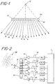
- a linear array 10 of individual transducer elements is shown.
- ultrasonic beams are transmitted from the array at angles increasing from the normal direction for ultrasonic beams emanating at increasing distances from the center of the array.
- a number of these beams are indicated at 4, 6, 8, 12, 14, and 16. All of the beams transmitted by the array 10 would appear to emanate from an origin O located behind the transmitting surface of the array.
- the area scanned in this manner thus represents a truncation of the conventional triangular sector area, with improved breadth of view in the near field as compared to a phased array, and improved breadth of view in the far field as compared to a linear array.
- the scanned area is seen to be in the form of a trapezoid, with the smaller parallel side of the trapezoid adjacent to the linear array 10 and the angular sides of the trapezoid at the lateral extremities of the array.
- ultrasonic beams are transmitted at angles which are incremented by uniform angular increments, proceeding from the center of the array 10.
- ultrasonic beam 4 in FIGURE 1 is the central beam in the scan field it is transmitted at an angle of 90 degrees with respect to the surface of the array 10.
- the adjacent beam 6 in this example is transmitted at an angle equal to 90 degrees + dt, where dt is a given angular increment delta theta.
- the next beam 8 in the scan field is transmitted at an angle of 90 degrees + 2dt.
- Beam 14 is transmitted at an angle which is offset from the angles of beams 12 and 16 by the same angular increment, dt.
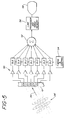
- FIGURE 2 illustrates in block diagram form apparatus for transmitting one of the angular beams 14 of FIGURE 1.
- the wavefront of this beam is transmitted at an angle ⁇ with respect to an axis which is normal to surface of the transducer array 10.
- Illustrative components of the transmitted wavefront which are launched by individual transducer elements E6, E8, E10, etc., are indicated at 28.
- a controller 1 transmits pulsar actuation signals through delay lines DL1 through DL5.
- the lengths of the respective delay lines progressively increase from DL5 through DL1. These times are indicated by the respective positions of pulsar actuation signals w5 through w1.
- Pulsar actuation signal w5 will actuate pulsar P5, which in turn will excite transducer element E6.
- pulsar actuation signals w4 through w1 will successively actuate pulsars P4 through P1, thereby exciting transducers E8 through E14.
- an off axis wavefront as indicated at 28 will emanate as a combined result of the actuation of the individual transducer elements E6 through E14.
- FIGURE 3a illustrates a technique for focusing the beam transmitted in direction 14 at focal point 22.
- the distances from the respective transducer elements to the focal point 22 are determined. Two of these distances a10 and b6 are indicated in FIGURE 3 for elements E10 and E6.
- the transit time of ultrasound from the respective transducer elements to the focal point 22 is determined.
- the interelement transit time differences are taken into account by the selection of the lengths of the delay lines DL1-DL5 in the excitation of the transducer elements to cause the steered beam to be focused in the vicinity of focal point 22.
- the image sector may be repetitively scanned with different focal points along the ultrasonic beam path 14 in order to assemble an image which is focused at numerous depths of field.
- FIGURE 3a illustrates the ultrasonic beam 14 as emanating from transducer array element E10, which is at the center of the aperture of beam 14. From the discussion of FIGURE 2 it may be appreciated that transducer element E6, when included in the aperture of beam 14, is actuated at a time preceding the actuation of element E10 by reason of the increased transit time of path b6 as compared with that of the shorter path a10. However, the time marker for the transmission of ultrasonic beam 14 is taken as the time of actuation of the effective central element, element E10 in FIGURE 3a, even though the central element is not the first to be actuated in the launching of the beam wavefront.
- FIGURE 3b the transmission and focusing of next adjacent ultrasonic beam 16 of the scan area is depicted in FIGURE 3b.
- Beam 16 is transmitted at an angle ⁇ 16, which is equal to ⁇ 14 + dt.
- the distance from the effective origin O to focal point 22', the interelement spacing X, and the angle ⁇ 16 are used to determine the distances a'10 and b'6 from the active transducer elements to the focal point 22', and the ultrasonic speed of the medium is used to determine corresponding transmit times.
- a data table of transit times and transit focal depths is assembled for the transducer groups used to transmit all of the ultrasonic beams of the scan field.
- the effective central element of the beam 16 is between elements E10 and E12 in FIGURE 3b.
- the time marker for the launching of ultrasonic beam 16 is neither the time of actuation of element E10 nor E12, but is a calculated time between two actuation times.
- each individual transducer element in the array has its own antenna pattern, often referred to as the element sensitivity pattern, which is not omni directional and generally favors signals coming from a direction normal to the transducer.
- Each exemplary sensitivity pattern is shown for respective transducer elements E8, E14 and E20 in FIGURE 4.
- the boundary of each sensitivity pattern indicates a constant level of reduced sensitivity taken with respect to peak sensitivity for each of the corresponding transducer elements.
- point 23 on ultrasonic beam 14 is within the limits of the sensitivity patterns A8 and A14 for respective elements E8 and E14.
- the point 23 is not within the sensitivity pattern of element E20, and hence elements E8 and E14 but not element E20 would be employed in focusing beam 14 at focal point 23.
- the point 25, however, is within the uniform sensitivity boundaries of all three sensitivity patterns A8, A14, and A20. Hence, when beam 14 is focused at point 25 all of the elements E8, E14, and E20, as well as intervening transducer elements, would be included in the beam aperture.
- Another technique for making the same determination of elements to include in the aperture for focusing at point 23 is to determine the sensitivity of individual transducer elements in the array to signals emanating from point 23 through a predetermined acoustic medium. Those falling within a range of sensitivity levels below a given threshold, such as 6dB below the signal strength of the transducer nearest the focal point, would be used in the aperture for point 23. At increasing depths of field the relative differences in sensitivity between adjacent transducer would decrease, and hence an increasing number of transducers would be used in the aperture for increased depths of focus.
- FIGURE 5 illustrates a returning echo wavefront 28', which is returning to the transducer array 10 in a direction indicated by arrow 34. As FIGURE 5 indicates, this wavefront will reach transducer element E5 first, then successively arrive at and be detected by elements E7 through E13.
- the received echo signal components are amplified by amplifiers indicated at 50, and delayed by respective delay lines indicated as DL1 through DL7. The lengths of the respective delay lines are controlled by timing and control subsystem 54.
- delay line DL5 would be the longest delay line employed to bring the echo signal components of angular beam 34 into time coincidence, with delay lines DL3, DL1, DL2, and DL4 being progressively shorter in length to focus the components of echo 28' received by elements E5 through E13.
- delay line lengths are properly staggered, signal components will be produced at the output of the delay lines in time synchronism and be summed constructively by summer 52.
- the echoes returning from increasing depths of field along beam direction 34 are processed and stored by line processor and image memory 56 and subsequently displayed on an image display 58.
- returning echo signals are focused and the array aperture during echo reception is varied according to the depth of returning signals.
- receive focusing and aperture is varied dynamically as echoes are received from the near to the far field.
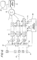
- FIGURE 6 illustrates in block diagram form an implementation of the receiving arrangement of FIGURE 5 which focuses received echo signal components over the full depth of field while varying the aperture of the transducer array.
- the individual elements E1 through En of the transducer array are connected to delay lines of appropriate length by way of individual receiver amplifiers 50 of the respective delay lines.
- the gain characteristics of the receiver amplifiers 50 may be shaped by selected time gain control signals as indicated at the TGC inputs of the receiver amplifiers.
- FIGURE 6 illustrates three of the delay line paths of the receiver arrangement; however, it is understood that there are as many delay line paths as there are elements in the transducer array 10.
- the echo signal components received by the receiver amplifiers 50 are digitized by respective analog to digital converters 70, 72, and 74 and the digitized signal samples are shifted into the input stages of ripple through register delay lines 80, 82, and 84 of lengths appropriate to the delays to be imparted to the respective echo components.
- the length of each delay line register must be at least of sufficient length to provide the maximum period of delay required by its associated transducer element during any scanning procedure.
- the delay line lengths are a function of the transit time differences of echo signal components from the various points of the scanned area to the respective transducer elements.
- the delay period of a particular delay line 80, 82 or 84 is determined by the starting times of echo signal sampling and the frequency at which the digitized samples are clocked into and out of the delay line, in consideration of the maximum angle ⁇ max at which beams are steered and the maximum aperture.
- the delay period required by each transducer element can be analyzed in terms of the delay required for focusing and the delay required for steering. In general, the central element of the array will require the largest focusing delay, with laterally disposed elements requiring lesser delays as a function of their distance from the central element. For steering delays, the most laterally disposed element in the direction of steering requires the greatest delay and the most laterally disposed element in the direction opposite the steering direction requires the shortest steering delay.
- the respective analog to digital converters and the input stages to delay lines 80, 82, and 84 are clocked by clock signals CF7, CF8, and CF9 developed by the central controller 88.
- clock signals CF7, CF8, and CF9 developed by the central controller 88.
- the disparity in distances from the tail of beam arrow 35 to elements E1, E8, and En is substantially less on a percentage basis.
- all the ultrasonic path lengths would be the same in this example.
- the sampling frequencies of selected analog to digital converters are continually varied. Since the distances to the laterally remote elements of the aperture are much greater than the distance to the central element of the aperture at near focal points but approach the distance to the central element as the range increases, it is necessary to sample the echoes in correspondence with this decline in distance disparity. This is accomplished by sampling at higher frequencies at the laterally remote elements, and decreasing the sampling frequencies as the focal depth increases.
- the frequencies of clock signals CF7, CF8, and CF9 decline from respective higher frequencies for near field focus, and approach on a continually varying basis some predetermined lower frequency as the depth of focus increases.
- the differently varying clock frequencies approach a nominal rate in the far field which is in the range of 10-30 MHz.
- the clock signals associated with laterally disposed transducer elements of the aperture which are at greater spatial distances to the initial focal point will have initial CF clock frequencies which are higher than those associated with transducer elements which are closer to the focal point.
- the samples As echo signal samples are docked into the delay lines 80, 82, and 84 the samples rapidly propagate through the intermediate central registers and accumulate in their sampling sequence at the end of the registers.
- the signal samples are then clocked out of the delay lines in time synchronism by output clock signals, OC5, OC6, and OC7.
- the output stages of the delay lines will thus normally be clocked in synchronism by the output clock signals, and the sequence of signal samples in the central registers will continually propagate to the output stages as signal samples are clocked out of the delay lines.
- the concurrently clocked output signal components of the delay lines 80, 82, and 84 are coherently summed by adders in a summing network 52, and the summed signals are then transmitted to the line processor and image memory 56 for display on the display 58.
- the output clock signals in addition to synchronously clocking the delayed echo signal components out of the output stages of the delay lines 80, 82, and 84, also control dynamic variation of the receive aperture.
- the number of transducer elements used in the receive aperture varies from a small number initially to a larger number in the far field, in accordance with the number of transducers satisfying a sensitivity criterion at different focal points as illustrated in FIGURE 4.
- the times at which laterally remote elements from the beam center begin to contribute to the active aperture is delayed until a sensitivity-determined depth of focus is reached at which time they are to be added to the aperture.
- the central controller 88 retards the times at which the input and output stages of the delay lines of laterally remote transducer elements of the aperture begin sampling and thus produces delayed output signals for summation with the other signal components of the aperture.
- a maximum delay of up to 340 microseconds can be provided before a respective transducer element participates in signal summation.
Applications Claiming Priority (3)
| Application Number | Priority Date | Filing Date | Title |
|---|---|---|---|
| US07/556,691 US5123415A (en) | 1990-07-19 | 1990-07-19 | Ultrasonic imaging by radial scan of trapezoidal sector |
| US556691 | 1990-07-19 | ||
| EP91306571A EP0467690B1 (fr) | 1990-07-19 | 1991-07-18 | Imagerie ultrasonore à balayage radial de secteur trapézoidal |
Related Parent Applications (2)
| Application Number | Title | Priority Date | Filing Date |
|---|---|---|---|
| EP91306571.0 Division | 1991-07-18 | ||
| EP91306571A Division EP0467690B1 (fr) | 1990-07-19 | 1991-07-18 | Imagerie ultrasonore à balayage radial de secteur trapézoidal |
Publications (3)
| Publication Number | Publication Date |
|---|---|
| EP0627635A2 true EP0627635A2 (fr) | 1994-12-07 |
| EP0627635A3 EP0627635A3 (en) | 1994-12-28 |
| EP0627635B1 EP0627635B1 (fr) | 1998-02-11 |
Family
ID=24222449
Family Applications (2)
| Application Number | Title | Priority Date | Filing Date |
|---|---|---|---|
| EP94202297A Expired - Lifetime EP0627635B1 (fr) | 1990-07-19 | 1991-07-18 | Imagerie ultrasonore à balayage radial de secteur trapézoidal |
| EP91306571A Expired - Lifetime EP0467690B1 (fr) | 1990-07-19 | 1991-07-18 | Imagerie ultrasonore à balayage radial de secteur trapézoidal |
Family Applications After (1)
| Application Number | Title | Priority Date | Filing Date |
|---|---|---|---|
| EP91306571A Expired - Lifetime EP0467690B1 (fr) | 1990-07-19 | 1991-07-18 | Imagerie ultrasonore à balayage radial de secteur trapézoidal |
Country Status (5)
| Country | Link |
|---|---|
| US (1) | US5123415A (fr) |
| EP (2) | EP0627635B1 (fr) |
| JP (1) | JP3135942B2 (fr) |
| AT (2) | ATE163232T1 (fr) |
| DE (2) | DE69114934T2 (fr) |
Cited By (12)
| Publication number | Priority date | Publication date | Assignee | Title |
|---|---|---|---|---|
| US5590658A (en) * | 1995-06-29 | 1997-01-07 | Teratech Corporation | Portable ultrasound imaging system |
| WO1997001768A2 (fr) * | 1995-06-29 | 1997-01-16 | Teratech Corporation | Systeme d'imagerie ultrasonique portatif |
| US5839442A (en) * | 1995-06-29 | 1998-11-24 | Teratech Corporation | Portable ultrasound imaging system |
| US5957846A (en) * | 1995-06-29 | 1999-09-28 | Teratech Corporation | Portable ultrasound imaging system |
| US5964709A (en) * | 1995-06-29 | 1999-10-12 | Teratech Corporation | Portable ultrasound imaging system |
| WO2001033251A1 (fr) * | 1999-11-03 | 2001-05-10 | Koninklijke Philips Electronics N.V. | Systeme d'imagerie diagnostique ultrasonore a balayage volumetrique uniforme |
| US7500952B1 (en) | 1995-06-29 | 2009-03-10 | Teratech Corporation | Portable ultrasound imaging system |
| US7527591B2 (en) | 2003-11-21 | 2009-05-05 | General Electric Company | Ultrasound probe distributed beamformer |
| US7527592B2 (en) | 2003-11-21 | 2009-05-05 | General Electric Company | Ultrasound probe sub-aperture processing |
| US9935254B2 (en) | 2008-09-18 | 2018-04-03 | Fujifilm Sonosite, Inc. | Methods for manufacturing ultrasound transducers and other components |
| US10596597B2 (en) | 2008-09-18 | 2020-03-24 | Fujifilm Sonosite, Inc. | Methods for manufacturing ultrasound transducers and other components |
| CN112353419A (zh) * | 2020-11-30 | 2021-02-12 | 简小华 | 多阵元扫描式超声波探头及超声成像系统和超声成像方法 |
Families Citing this family (42)
| Publication number | Priority date | Publication date | Assignee | Title |
|---|---|---|---|---|
| US5744898A (en) * | 1992-05-14 | 1998-04-28 | Duke University | Ultrasound transducer array with transmitter/receiver integrated circuitry |
| US5329496A (en) * | 1992-10-16 | 1994-07-12 | Duke University | Two-dimensional array ultrasonic transducers |
| GB2301892B (en) * | 1992-07-14 | 1997-02-26 | Intravascular Res Ltd | Methods and apparatus for the examination and treatment of internal organs |
| US5322068A (en) * | 1993-05-21 | 1994-06-21 | Hewlett-Packard Company | Method and apparatus for dynamically steering ultrasonic phased arrays |
| US5798461A (en) * | 1993-06-02 | 1998-08-25 | Hewlett-Packard Company | Methods and apparatus for ultrasound imaging using combined scan patterns |
| US5379642A (en) * | 1993-07-19 | 1995-01-10 | Diasonics Ultrasound, Inc. | Method and apparatus for performing imaging |
| JP3059042B2 (ja) * | 1994-02-22 | 2000-07-04 | フクダ電子株式会社 | 超音波診断装置 |
| US5685308A (en) * | 1994-08-05 | 1997-11-11 | Acuson Corporation | Method and apparatus for receive beamformer system |
| US5675554A (en) * | 1994-08-05 | 1997-10-07 | Acuson Corporation | Method and apparatus for transmit beamformer |
| AU3361095A (en) * | 1994-08-05 | 1996-03-04 | Acuson Corporation | Method and apparatus for transmit beamformer system |
| GB2293240B (en) * | 1994-09-15 | 1998-05-20 | Intravascular Res Ltd | Ultrasonic visualisation method and apparatus |
| US5544655A (en) | 1994-09-16 | 1996-08-13 | Atlantis Diagnostics International, Llc | Ultrasonic multiline beamforming with interleaved sampling |
| US5438994A (en) * | 1994-10-07 | 1995-08-08 | Advanced Technology Laboratories, Inc. | Ultrasonic diagnostic image scanning |
| EP0705564B1 (fr) * | 1994-10-07 | 2004-02-04 | Advanced Technology Laboratories, Inc. | Techniques de reproduction d'images diagnostiques à balayage ultrasonore |
| US8241217B2 (en) | 1995-06-29 | 2012-08-14 | Teratech Corporation | Portable ultrasound imaging data |
| US6254542B1 (en) | 1995-07-17 | 2001-07-03 | Intravascular Research Limited | Ultrasonic visualization method and apparatus |
| EP0883860B1 (fr) * | 1996-02-29 | 2006-08-23 | Acuson Corporation | Systeme, procede et tansducteur d'alignement d'images ultrasonores multiples |
| US5817024A (en) * | 1996-06-28 | 1998-10-06 | Sonosight, Inc. | Hand held ultrasonic diagnostic instrument with digital beamformer |
| US7819807B2 (en) * | 1996-06-28 | 2010-10-26 | Sonosite, Inc. | Balance body ultrasound system |
| US6416475B1 (en) | 1996-06-28 | 2002-07-09 | Sonosite, Inc. | Ultrasonic signal processor for a hand held ultrasonic diagnostic instrument |
| US6045508A (en) | 1997-02-27 | 2000-04-04 | Acuson Corporation | Ultrasonic probe, system and method for two-dimensional imaging or three-dimensional reconstruction |
| US6669633B2 (en) | 1999-06-22 | 2003-12-30 | Teratech Corporation | Unitary operator control for ultrasonic imaging graphical user interface |
| US20040015079A1 (en) | 1999-06-22 | 2004-01-22 | Teratech Corporation | Ultrasound probe with integrated electronics |
| US9402601B1 (en) | 1999-06-22 | 2016-08-02 | Teratech Corporation | Methods for controlling an ultrasound imaging procedure and providing ultrasound images to an external non-ultrasound application via a network |
| US6685645B1 (en) | 2001-10-20 | 2004-02-03 | Zonare Medical Systems, Inc. | Broad-beam imaging |
| US6725721B2 (en) * | 2001-10-22 | 2004-04-27 | Magnetic Analysis Corporation | Ultrasonic multi-element transducers and methods for testing |
| US7331234B2 (en) * | 2002-11-13 | 2008-02-19 | Fujifilm Corporation | Ultrasonic imaging method and ultrasonic imaging apparatus |
| US20050113698A1 (en) * | 2003-11-21 | 2005-05-26 | Kjell Kristoffersen | Ultrasound probe transceiver circuitry |
| WO2005104210A2 (fr) * | 2004-04-20 | 2005-11-03 | Visualsonics Inc. | Transducteur ultrasonique en reseau |
| US8066642B1 (en) | 2005-05-03 | 2011-11-29 | Sonosite, Inc. | Systems and methods for ultrasound beam forming data control |
| EP1952175B1 (fr) | 2005-11-02 | 2013-01-09 | Visualsonics, Inc. | Formateur de faisceaux digital pour un système ultrasonore à réseau de transducteurs |
| KR100936454B1 (ko) | 2006-08-18 | 2010-01-13 | 주식회사 메디슨 | 스캔라인을 제어하는 초음파 시스템 및 방법 |
| US7757559B2 (en) | 2007-05-25 | 2010-07-20 | Magnetic Analysis Corporation | Oblique flaw detection using ultrasonic transducers |
| US8137278B2 (en) * | 2007-09-12 | 2012-03-20 | Sonosite, Inc. | System and method for spatial compounding using phased arrays |
| US20110144494A1 (en) | 2008-09-18 | 2011-06-16 | James Mehi | Methods for acquisition and display in ultrasound imaging |
| US20100228130A1 (en) * | 2009-03-09 | 2010-09-09 | Teratech Corporation | Portable ultrasound imaging system |
| US9177543B2 (en) | 2009-08-26 | 2015-11-03 | Insightec Ltd. | Asymmetric ultrasound phased-array transducer for dynamic beam steering to ablate tissues in MRI |
| US8661873B2 (en) | 2009-10-14 | 2014-03-04 | Insightec Ltd. | Mapping ultrasound transducers |
| US9852727B2 (en) | 2010-04-28 | 2017-12-26 | Insightec, Ltd. | Multi-segment ultrasound transducers |
| RU2650738C2 (ru) | 2013-03-25 | 2018-04-17 | Конинклейке Филипс Н.В. | Ультразвуковая диагностическая система визуализации с пространственным составлением трапецеидального сектора |
| CN105027219B (zh) * | 2013-03-28 | 2018-09-11 | 株式会社日立制作所 | 延迟电路、使用延迟电路的电子电路以及超声波拍摄装置 |
| JP7211150B2 (ja) | 2019-02-21 | 2023-01-24 | コニカミノルタ株式会社 | 超音波診断装置、超音波画像生成方法及びプログラム |
Citations (5)
| Publication number | Priority date | Publication date | Assignee | Title |
|---|---|---|---|---|
| US4446740A (en) * | 1982-03-09 | 1984-05-08 | Sri International | Frequency controlled hybrid ultrasonic imaging arrays |
| EP0119911A1 (fr) * | 1983-03-18 | 1984-09-26 | Cgr Ultrasonic | Procédé d'imagerie par ultrasons à partir d'un alignement d'éléments transducteurs |
| US4567897A (en) * | 1983-08-19 | 1986-02-04 | Kabushiki Kaisha Toshiba | Ultrasonic diagnostic apparatus |
| US4664122A (en) * | 1984-07-25 | 1987-05-12 | Kabushiki Kaisha Toshiba | Ultrasonic transducer array used in ultrasonic diagnosis apparatus |
| EP0442450A2 (fr) * | 1990-02-12 | 1991-08-21 | Acuson Corporation | Procédé et dispositif pour le scanning acoustique avec origine variable et angle variable |
Family Cites Families (15)
| Publication number | Priority date | Publication date | Assignee | Title |
|---|---|---|---|---|
| DE2643918C3 (de) * | 1976-09-29 | 1986-10-23 | Siemens AG, 1000 Berlin und 8000 München | Gerät zur Ultraschallabtastung |
| US4159462A (en) * | 1977-08-18 | 1979-06-26 | General Electric Company | Ultrasonic multi-sector scanner |
| US4180790A (en) * | 1977-12-27 | 1979-12-25 | General Electric Company | Dynamic array aperture and focus control for ultrasonic imaging systems |
| JPS5578947A (en) * | 1978-12-08 | 1980-06-14 | Matsushita Electric Ind Co Ltd | Method of displaying ultrasoniccwave diagnosis device |
| US4241610A (en) * | 1979-02-05 | 1980-12-30 | Varian Associates, Inc. | Ultrasonic imaging system utilizing dynamic and pseudo-dynamic focusing |
| US4290310A (en) * | 1979-07-09 | 1981-09-22 | Varian Associates, Inc. | Ultrasonic imaging system using digital control |
| JPS5672857A (en) * | 1979-11-16 | 1981-06-17 | Matsushita Electric Ind Co Ltd | Method of scanning ultrasonic diagnosing device |
| JPS60103944A (ja) * | 1983-11-10 | 1985-06-08 | 株式会社東芝 | 超音波検査装置 |
| US4691570A (en) * | 1984-03-12 | 1987-09-08 | Dietrich Hassler | Method and apparatus for ultrasonically scanning a subject with an ultrasound head |
| CA1242267A (fr) * | 1984-09-25 | 1988-09-20 | Rainer Fehr | Affichage en temps reel d'une image composite engendree par ultrasons |
| EP0186290B1 (fr) * | 1984-11-09 | 1992-01-15 | Matsushita Electric Industrial Co., Ltd. | Système d'imagerie ultrasonore pour l'affichage simultané d'images multiples à balayage sectoriel |
| US4644795A (en) * | 1985-07-29 | 1987-02-24 | Advanced Technology Laboratories, Inc. | High resolution multiline ultrasonic beamformer |
| FR2625562B1 (fr) * | 1987-12-30 | 1990-12-28 | Labo Electronique Physique | Echographe ultrasonore a cadence d'images amelioree |
| US5005419A (en) * | 1988-06-16 | 1991-04-09 | General Electric Company | Method and apparatus for coherent imaging system |
| US4937797A (en) * | 1988-11-14 | 1990-06-26 | Hewlett-Packard Company | Method and apparatus for controlling scan line direction in a linear array ultrasonic doppler scanning system |
-
1990
- 1990-07-19 US US07/556,691 patent/US5123415A/en not_active Expired - Lifetime
-
1991
- 1991-07-18 DE DE69114934T patent/DE69114934T2/de not_active Expired - Fee Related
- 1991-07-18 EP EP94202297A patent/EP0627635B1/fr not_active Expired - Lifetime
- 1991-07-18 DE DE69128919T patent/DE69128919T2/de not_active Expired - Fee Related
- 1991-07-18 AT AT94202297T patent/ATE163232T1/de not_active IP Right Cessation
- 1991-07-18 AT AT91306571T patent/ATE130939T1/de not_active IP Right Cessation
- 1991-07-18 EP EP91306571A patent/EP0467690B1/fr not_active Expired - Lifetime
- 1991-07-18 JP JP03177914A patent/JP3135942B2/ja not_active Expired - Fee Related
Patent Citations (5)
| Publication number | Priority date | Publication date | Assignee | Title |
|---|---|---|---|---|
| US4446740A (en) * | 1982-03-09 | 1984-05-08 | Sri International | Frequency controlled hybrid ultrasonic imaging arrays |
| EP0119911A1 (fr) * | 1983-03-18 | 1984-09-26 | Cgr Ultrasonic | Procédé d'imagerie par ultrasons à partir d'un alignement d'éléments transducteurs |
| US4567897A (en) * | 1983-08-19 | 1986-02-04 | Kabushiki Kaisha Toshiba | Ultrasonic diagnostic apparatus |
| US4664122A (en) * | 1984-07-25 | 1987-05-12 | Kabushiki Kaisha Toshiba | Ultrasonic transducer array used in ultrasonic diagnosis apparatus |
| EP0442450A2 (fr) * | 1990-02-12 | 1991-08-21 | Acuson Corporation | Procédé et dispositif pour le scanning acoustique avec origine variable et angle variable |
Non-Patent Citations (1)
| Title |
|---|
| ULTRASONIC IMAGING, vol.12, no.1, 31 January 1990, DULUTH, MN, US pages 1 - 16 SONG ET AL. 'A NEW DIGITAL PHASEDD ARRAY SYSTEM FOR DYNAMIC FOCUSING AND STEERING WITH REDUCEX SAMPLING RATE' * |
Cited By (18)
| Publication number | Priority date | Publication date | Assignee | Title |
|---|---|---|---|---|
| US7500952B1 (en) | 1995-06-29 | 2009-03-10 | Teratech Corporation | Portable ultrasound imaging system |
| WO1997001768A2 (fr) * | 1995-06-29 | 1997-01-16 | Teratech Corporation | Systeme d'imagerie ultrasonique portatif |
| WO1997001768A3 (fr) * | 1995-06-29 | 1997-01-30 | Teratech Corp | Systeme d'imagerie ultrasonique portatif |
| US5690114A (en) * | 1995-06-29 | 1997-11-25 | Teratech Corporation | Portable ultrasound imaging system |
| US5839442A (en) * | 1995-06-29 | 1998-11-24 | Teratech Corporation | Portable ultrasound imaging system |
| US5957846A (en) * | 1995-06-29 | 1999-09-28 | Teratech Corporation | Portable ultrasound imaging system |
| US5964709A (en) * | 1995-06-29 | 1999-10-12 | Teratech Corporation | Portable ultrasound imaging system |
| US6106472A (en) * | 1995-06-29 | 2000-08-22 | Teratech Corporation | Portable ultrasound imaging system |
| US5590658A (en) * | 1995-06-29 | 1997-01-07 | Teratech Corporation | Portable ultrasound imaging system |
| WO2001033251A1 (fr) * | 1999-11-03 | 2001-05-10 | Koninklijke Philips Electronics N.V. | Systeme d'imagerie diagnostique ultrasonore a balayage volumetrique uniforme |
| US7527591B2 (en) | 2003-11-21 | 2009-05-05 | General Electric Company | Ultrasound probe distributed beamformer |
| US7527592B2 (en) | 2003-11-21 | 2009-05-05 | General Electric Company | Ultrasound probe sub-aperture processing |
| US9935254B2 (en) | 2008-09-18 | 2018-04-03 | Fujifilm Sonosite, Inc. | Methods for manufacturing ultrasound transducers and other components |
| US10596597B2 (en) | 2008-09-18 | 2020-03-24 | Fujifilm Sonosite, Inc. | Methods for manufacturing ultrasound transducers and other components |
| US11094875B2 (en) | 2008-09-18 | 2021-08-17 | Fujifilm Sonosite, Inc. | Methods for manufacturing ultrasound transducers and other components |
| US11845108B2 (en) | 2008-09-18 | 2023-12-19 | Fujifilm Sonosite, Inc. | Methods for manufacturing ultrasound transducers and other components |
| CN112353419A (zh) * | 2020-11-30 | 2021-02-12 | 简小华 | 多阵元扫描式超声波探头及超声成像系统和超声成像方法 |
| CN112353419B (zh) * | 2020-11-30 | 2024-03-15 | 中国科学院苏州生物医学工程技术研究所 | 多阵元扫描式超声波探头及超声成像系统和超声成像方法 |
Also Published As
| Publication number | Publication date |
|---|---|
| DE69128919T2 (de) | 1998-08-13 |
| EP0467690A3 (en) | 1992-12-02 |
| ATE163232T1 (de) | 1998-02-15 |
| DE69114934D1 (de) | 1996-01-11 |
| EP0627635A3 (en) | 1994-12-28 |
| JP3135942B2 (ja) | 2001-02-19 |
| DE69114934T2 (de) | 1996-05-23 |
| US5123415A (en) | 1992-06-23 |
| JPH04232888A (ja) | 1992-08-21 |
| EP0467690A2 (fr) | 1992-01-22 |
| DE69128919D1 (de) | 1998-03-19 |
| ATE130939T1 (de) | 1995-12-15 |
| EP0627635B1 (fr) | 1998-02-11 |
| EP0467690B1 (fr) | 1995-11-29 |
Similar Documents
| Publication | Publication Date | Title |
|---|---|---|
| EP0467690B1 (fr) | Imagerie ultrasonore à balayage radial de secteur trapézoidal | |
| JP2807113B2 (ja) | 音響走査方法及び装置 | |
| US5844139A (en) | Method and apparatus for providing dynamically variable time delays for ultrasound beamformer | |
| US8672846B2 (en) | Continuous transmit focusing method and apparatus for ultrasound imaging system | |
| US5566675A (en) | Beamformer for phase aberration correction | |
| US6638227B2 (en) | Ultrasound imaging method and apparatus using orthogonal Golay codes | |
| US5487306A (en) | Phase aberration correction in phased-array imaging systems | |
| US5419330A (en) | Ultrasonic diagnostic equipment | |
| US5817023A (en) | Ultrasound imaging system with dynamic window function generator | |
| US20040187583A1 (en) | Ultrasonic transmitting and receiving apparatus | |
| JP2000157548A (ja) | 超音波散乱体をイメ―ジングするための方法及びシステム | |
| US6736780B2 (en) | Synthetic aperture focusing method for ultrasound imaging based on planar waves | |
| US6669640B2 (en) | Ultrasound imaging system using multi-stage pulse compression | |
| Dietz et al. | Expanding-aperture annular array | |
| US4460987A (en) | Variable focus sonar with curved array | |
| US5476098A (en) | Partially coherent imaging for large-aperture phased arrays | |
| US5548561A (en) | Ultrasound image enhancement using beam-nulling | |
| US5642329A (en) | Method for doubling the resolving power of a sonar array and a sonar array for implementing the same | |
| US20040193050A1 (en) | Ultrasonic transmitting and receiving apparatus | |
| JPH02209135A (ja) | 超音波送受信装置 | |
| JP2003220059A (ja) | 超音波撮像システムでの合成開口集束方法 | |
| JP3202969B2 (ja) | 波動受信装置 | |
| JP4643807B2 (ja) | 超音波計測装置 | |
| JP4154043B2 (ja) | 超音波撮像装置 | |
| JP2001104307A (ja) | 柔軟性のある受信ビームフォーミング用集積回路アーキテクチャ |
Legal Events
| Date | Code | Title | Description |
|---|---|---|---|
| PUAI | Public reference made under article 153(3) epc to a published international application that has entered the european phase |
Free format text: ORIGINAL CODE: 0009012 |
|
| PUAL | Search report despatched |
Free format text: ORIGINAL CODE: 0009013 |
|
| AC | Divisional application: reference to earlier application |
Ref document number: 467690 Country of ref document: EP |
|
| AK | Designated contracting states |
Kind code of ref document: A2 Designated state(s): AT BE CH DE DK ES FR GB GR IT LI LU NL SE |
|
| AK | Designated contracting states |
Kind code of ref document: A3 Designated state(s): AT BE CH DE DK ES FR GB GR IT LI LU NL SE |
|
| 17P | Request for examination filed |
Effective date: 19950511 |
|
| 17Q | First examination report despatched |
Effective date: 19960628 |
|
| GRAG | Despatch of communication of intention to grant |
Free format text: ORIGINAL CODE: EPIDOS AGRA |
|
| GRAG | Despatch of communication of intention to grant |
Free format text: ORIGINAL CODE: EPIDOS AGRA |
|
| GRAH | Despatch of communication of intention to grant a patent |
Free format text: ORIGINAL CODE: EPIDOS IGRA |
|
| GRAH | Despatch of communication of intention to grant a patent |
Free format text: ORIGINAL CODE: EPIDOS IGRA |
|
| GRAA | (expected) grant |
Free format text: ORIGINAL CODE: 0009210 |
|
| AC | Divisional application: reference to earlier application |
Ref document number: 467690 Country of ref document: EP |
|
| AK | Designated contracting states |
Kind code of ref document: B1 Designated state(s): AT BE CH DE DK ES FR GB GR IT LI LU NL SE |
|
| PG25 | Lapsed in a contracting state [announced via postgrant information from national office to epo] |
Ref country code: LI Free format text: LAPSE BECAUSE OF FAILURE TO SUBMIT A TRANSLATION OF THE DESCRIPTION OR TO PAY THE FEE WITHIN THE PRESCRIBED TIME-LIMIT Effective date: 19980211 Ref country code: GR Free format text: LAPSE BECAUSE OF FAILURE TO SUBMIT A TRANSLATION OF THE DESCRIPTION OR TO PAY THE FEE WITHIN THE PRESCRIBED TIME-LIMIT Effective date: 19980211 Ref country code: ES Free format text: THE PATENT HAS BEEN ANNULLED BY A DECISION OF A NATIONAL AUTHORITY Effective date: 19980211 Ref country code: CH Free format text: LAPSE BECAUSE OF FAILURE TO SUBMIT A TRANSLATION OF THE DESCRIPTION OR TO PAY THE FEE WITHIN THE PRESCRIBED TIME-LIMIT Effective date: 19980211 Ref country code: BE Free format text: LAPSE BECAUSE OF FAILURE TO SUBMIT A TRANSLATION OF THE DESCRIPTION OR TO PAY THE FEE WITHIN THE PRESCRIBED TIME-LIMIT Effective date: 19980211 Ref country code: AT Free format text: LAPSE BECAUSE OF FAILURE TO SUBMIT A TRANSLATION OF THE DESCRIPTION OR TO PAY THE FEE WITHIN THE PRESCRIBED TIME-LIMIT Effective date: 19980211 |
|
| REF | Corresponds to: |
Ref document number: 163232 Country of ref document: AT Date of ref document: 19980215 Kind code of ref document: T |
|
| REG | Reference to a national code |
Ref country code: CH Ref legal event code: EP |
|
| REF | Corresponds to: |
Ref document number: 69128919 Country of ref document: DE Date of ref document: 19980319 |
|
| ET | Fr: translation filed | ||
| ITF | It: translation for a ep patent filed |
Owner name: STUDIO TORTA S.R.L. |
|
| PG25 | Lapsed in a contracting state [announced via postgrant information from national office to epo] |
Ref country code: SE Free format text: LAPSE BECAUSE OF FAILURE TO SUBMIT A TRANSLATION OF THE DESCRIPTION OR TO PAY THE FEE WITHIN THE PRESCRIBED TIME-LIMIT Effective date: 19980511 Ref country code: DK Free format text: LAPSE BECAUSE OF FAILURE TO SUBMIT A TRANSLATION OF THE DESCRIPTION OR TO PAY THE FEE WITHIN THE PRESCRIBED TIME-LIMIT Effective date: 19980511 |
|
| PG25 | Lapsed in a contracting state [announced via postgrant information from national office to epo] |
Ref country code: LU Free format text: LAPSE BECAUSE OF NON-PAYMENT OF DUE FEES Effective date: 19980718 |
|
| REG | Reference to a national code |
Ref country code: CH Ref legal event code: PL |
|
| PLBE | No opposition filed within time limit |
Free format text: ORIGINAL CODE: 0009261 |
|
| STAA | Information on the status of an ep patent application or granted ep patent |
Free format text: STATUS: NO OPPOSITION FILED WITHIN TIME LIMIT |
|
| 26N | No opposition filed | ||
| PGFP | Annual fee paid to national office [announced via postgrant information from national office to epo] |
Ref country code: GB Payment date: 19990723 Year of fee payment: 9 |
|
| PGFP | Annual fee paid to national office [announced via postgrant information from national office to epo] |
Ref country code: FR Payment date: 19990727 Year of fee payment: 9 |
|
| PGFP | Annual fee paid to national office [announced via postgrant information from national office to epo] |
Ref country code: NL Payment date: 19990730 Year of fee payment: 9 |
|
| PGFP | Annual fee paid to national office [announced via postgrant information from national office to epo] |
Ref country code: DE Payment date: 19990826 Year of fee payment: 9 |
|
| PG25 | Lapsed in a contracting state [announced via postgrant information from national office to epo] |
Ref country code: GB Free format text: LAPSE BECAUSE OF NON-PAYMENT OF DUE FEES Effective date: 20000718 |
|
| PG25 | Lapsed in a contracting state [announced via postgrant information from national office to epo] |
Ref country code: NL Free format text: LAPSE BECAUSE OF NON-PAYMENT OF DUE FEES Effective date: 20010201 |
|
| GBPC | Gb: european patent ceased through non-payment of renewal fee |
Effective date: 20000718 |
|
| PG25 | Lapsed in a contracting state [announced via postgrant information from national office to epo] |
Ref country code: FR Free format text: LAPSE BECAUSE OF NON-PAYMENT OF DUE FEES Effective date: 20010330 |
|
| NLV4 | Nl: lapsed or anulled due to non-payment of the annual fee |
Effective date: 20010201 |
|
| REG | Reference to a national code |
Ref country code: FR Ref legal event code: ST |
|
| PG25 | Lapsed in a contracting state [announced via postgrant information from national office to epo] |
Ref country code: DE Free format text: LAPSE BECAUSE OF NON-PAYMENT OF DUE FEES Effective date: 20010501 |
|
| PG25 | Lapsed in a contracting state [announced via postgrant information from national office to epo] |
Ref country code: IT Free format text: LAPSE BECAUSE OF NON-PAYMENT OF DUE FEES Effective date: 20050718 |