EP0625833B1 - Sendeleistungssteuerung einer Mobil-Station in einem Mobil-Funktelefonsystem - Google Patents
Sendeleistungssteuerung einer Mobil-Station in einem Mobil-Funktelefonsystem Download PDFInfo
- Publication number
- EP0625833B1 EP0625833B1 EP94303324A EP94303324A EP0625833B1 EP 0625833 B1 EP0625833 B1 EP 0625833B1 EP 94303324 A EP94303324 A EP 94303324A EP 94303324 A EP94303324 A EP 94303324A EP 0625833 B1 EP0625833 B1 EP 0625833B1
- Authority
- EP
- European Patent Office
- Prior art keywords
- signal
- level
- circuit
- amplifier
- transmission
- Prior art date
- Legal status (The legal status is an assumption and is not a legal conclusion. Google has not performed a legal analysis and makes no representation as to the accuracy of the status listed.)
- Expired - Lifetime
Links
Images




Classifications
-
- H—ELECTRICITY
- H04—ELECTRIC COMMUNICATION TECHNIQUE
- H04B—TRANSMISSION
- H04B1/00—Details of transmission systems, not covered by a single one of groups H04B3/00 - H04B13/00; Details of transmission systems not characterised by the medium used for transmission
- H04B1/02—Transmitters
- H04B1/04—Circuits
-
- H—ELECTRICITY
- H04—ELECTRIC COMMUNICATION TECHNIQUE
- H04W—WIRELESS COMMUNICATION NETWORKS
- H04W52/00—Power management, e.g. Transmission Power Control [TPC] or power classes
- H04W52/04—Transmission power control [TPC]
- H04W52/52—Transmission power control [TPC] using AGC [Automatic Gain Control] circuits or amplifiers
Definitions
- the present invention relates to a radio communication apparatus and, more particularly, to an apparatus where the output level of a transmission signal is adjustable.
- a base station In a duplex mobile telephone system inclusive of portable telephone and car telephone, such as a cellular phone system, a base station is capable of controlling or designating the transmission output power of a mobile station. The purpose is to reduce the transmission output of the mobile station to the minimum value required for the base station, so as to increase the number of mobile stations, which can utilize the system, by using the same channel even in a cell (service area) of another base station.
- the control or designation of the transmission output of a mobile station is realized by transmission of a code termed MAC (Mobile Attenuation Code) from the base station to the mobile station.
- MAC Mobile Attenuation Code
- FIG. 1 of the accompanying drawings More specifically, the MAC is 3 bits of data, and therefore it is possible to designate the transmission output in a maximum of 8 steps.
- the transmission output is classified into three classes from 1 to 3; i.e., class 1 is assigned to car telephone or the like, class 2 to car telephone and shoulder type mobile telephone, and class 3 to handy type portable telephone, respectively.
- a car telephone of class 1 its transmission output is controlled or designated in 8 steps at an interval of 4 dB.
- its maximum output is predetermined to be less than half the value of that of a car telephone in class 1 in order to increase the service life of the battery used as a power supply.
- the allowable error range of each transmission output is set to be relatively wide as shown in FIG. 1.
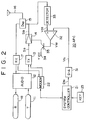
- FIG. 2 is a block diagram of a radio communication apparatus on which the present invention is based.
- FIG. 2 there are shown a mouthpiece 11, an audio circuit 12, a transmitting circuit 13, a power amplifier 14, a duplexer 15, a transmitting/receiving antenna 16, a receiving circuit 17, and an earpiece 18.
- a down-channel FM signal (transmission signal) from the base station is received at the antenna 16.
- the signal thus received is supplied via the duplexer 15 to the receiving circuit 17, so that the sound signal from the talker is extracted. Thereafter the sound signal thus extracted is supplied via the audio circuit 12 to the earpiece 18.
- Denoted by 21 is a system controller which consists of a microcomputer.
- the transmitting circuit 13 and the receiving circuit 17 are connected to each other via a modem circuit 22, whereby a predetermined command signal or data such as MAC can be accessed between the system controller 21 and the base station. Further the audio circuit 12, the transmitting circuit 13 and the receiving circuit 17 are controlled by the system controller 21 in response to the command signal or the data received from the base station.
- Denoted by 23 is an operation key such as a dial key or a talk key.
- Reference numeral 30 denotes an APC (Auto Power Control) circuit for controlling the transmission output in accordance with the MAC.
- Data D31 is obtained from a latched output port of the system controller 21.
- the data D31 is used for designating the transmission output and has, e.g., complementary correlation to the MAC.
- the data D31 is supplied to a D-A converter 31, where a digital-to-analog conversion is executed to convert the data D31 into an analog voltage V31.
- the voltage V31 thus obtained through the digital-to-analog conversion is supplied as a reference voltage to a voltage comparator 32.
- the transmission signal from the power amplifier 14 is partially supplied to a detector 33, which then outputs a DC-voltage V33 of a level corresponding to the level or amplitude of the transmission signal S13, and then the voltage V33 is supplied to the comparator 32.
- the emitter-collector junction of a transistor 35 is connected in series between a power supply terminal 34 and a power line of the amplifier 14, and a comparison output voltage V32 obtained from the comparator 32 is supplied to the base of the transistor 35 as a control signal for the transistor 35.
- the level of the transmission signal S13 can be controlled in the system controller 21 by controlling the value of the data D31, whereby the base station is able to control or designate the transmission output of the mobile station in accordance with the MAC.
- the transmission output of a mobile station is reduced to the minimum necessary value.
- fine designation of the transmission output is not executed by a base station, and the maximum output is permitted in most cases. As a result, the current consumption in a mobile station is large.
- the mobile station is a car telephone of class 1
- a portable telephone of the class 3 which uses the battery incorporated therein for its operation, the service life of the battery is shortened if the current consumption is great, hence shortening the effective time for communication.
- the allowable range of the transmission output is as wide as +2 dB to -4 dB (or -2 dB).
- the current consumption thereof varies widely depending on whether the transmission output is set to a rated value of +2 dB or -2 dB, whereby the service life of the battery is considerably changed.
- US-5,129,098 describes a system where a CPU samples the incoming signal power level, averages it over time and provides an appropriate calibration factor to determine the required power amplifier output.
- GB-A-2,299,609 describes a system where the base station transmits a power level designation code to a mobile unit. If the field level of the received signal is equal to or higher than a predetermined field level and the power level designation code is at maximum power, then the output power level is decreased.
- EP-A-0,392,079 describes a system in which the level of the received signal is detected. If it is higher than a reference value, the output power level is reduced.
- a radio communication apparatus comprising:
- control circuit controls said amplifier, in response to the detection output of said detecting circuit, in such a manner that, when the result of the detection signifies that the error rate of the signal transmitted from said opposite station in the low-level mode of said transmission signal fails to satisfy the preset value, the level of said transmission signal is raised within the prescribed range.
- the control circuit may be operable to switch the transmission signal selectively from a high-level mode to a low-level mode or from a low-level mode to a high-level mode according to said detected error rate.
- the current consumption can be reduced, in a call mode, by lowering the output level of the transmission signal only when the reception state of the signal transmitted from the opposite station satisfies the predetermined condition. It is considered that, when the reception state satisfies the predetermined condition, the opposite station is also receiving the radio waves exactly, hence preventing deterioration of the speech quality. Furthermore, if a battery is used as a power supply, it becomes possible to prolong the service life of the battery. In addition, since the output level of the transmission signal is lowered, it is possible to reduce a disturbance to the opposite station. Besides the above, due to the contrivance that the output level of the transmission signal is adjusted within the allowable range of the transmission output, there occurs no deterioration of the speech quality.
- FIG. 3 shows an analog portable telephone, wherein like component elements corresponding to those in FIG. 2 are denoted by the same reference numerals, and a detailed description thereof conforms with the foregoing explanation.
- the telephone of FIG. 3 is not in accordance with the present invention but is useful for understanding the present invention.
- An intermediate-frequency signal for example is supplied from a receiving circuit 17 to a detecting circuit 41, and a signal voltage V41 representing the reception level of a down-channel FM signal is outputted from the circuit 41.
- the voltage V41 thus obtained is supplied to an A-D converter 42 where analog-to-digital conversion is executed. Thereafter the signal V41 obtained through such analog-to-digital conversion is supplied to a system controller 21 as a parameter indicating the reception state of the down-channel FM signal.
- a control routine 100 of FIG. 5 for example is prepared to execute selective switching of the transmission output to an H mode or an L mode under control.
- this control routine 100 a process for controlling the transmission output by the MAC received from a base station, and also a process for clear-down.
- step 101 of the control routine 100 When a power supply is turned on in this construction, the processing sequence of the system controller 21 starts from step 101 of the control routine 100. Then at step 102, the component circuits are initialized. Thereafter at step 103, a check is executed as to whether a request for a terminating call or an originating call is existent or not. And if the result of such check signifies none of request, the process of step 103 is repeated. In this manner, when the power supply is turned on, the telephone is placed in s standby mode. In this standby mode, some partial circuits inclusive of the receiving circuit and the system controller 21 operate to monitor a terminating call request in a control channel while monitoring an originating call request from a key 23.
- step 103 When a terminating call request or an originating call request arrives in such a standby mode, the request is detected at step 103, and subsequently the processing sequence of the system controller 21 proceeds from step 103 to step 111.
- step 111 a process for connection to the base station is executed with setting of the transmission output to its maximum output level.
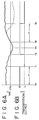
- step 112 Upon completion of the connection to the base station, the processing sequence advances to step 112 where, as indicated at a time point t0 in FIG. 6B for example, the transmission output is set to an H mode (great output mode) out of those corresponding to the MAC designated by the base station.
- a detection voltage V41 representing the reception level is higher than a predetermined threshold level VTH. In this manner, the telephone is shifted from step 111 to a call mode.
- step 113 a wait is executed for a time period ⁇ , e.g., 10 seconds, from the time point t0 to a next time point t1. Therefore, during the first period ⁇ after connection of the telephone to the base station at the time point t0, a call is effected in the H mode regardless of any state of radio waves.
- a time period ⁇ e.g. 10 seconds
- step 114 a check is executed by the detection voltage V41 as to whether the reception level of the down-channel FM signal from the base station is above the predetermined threshold value or not. In other words, a check is executed as to whether the condition is V41 ⁇ VTH or not. If the result of such check signifies that the condition is not V41 ⁇ VTH, the process of step 114 is repeated. Accordingly, when the reception level of the down-channel FM signal is below the predetermined threshold value VTH, the call mode is kept on continuously with the transmission output being maintained in the H mode.
- step 114 when the result of the check at step 114 signifies that the condition is V41 ⁇ VTH as indicated at the time point tl in FIG. 6A, the processing sequence proceeds from step 114 to step 115. At this step 115, as indicated at the time point tl in FIG. 6B, the transmission output is switched to an L mode. Thereafter the processing sequence advances to step 116. At this step, a check is executed again as to whether the condition is V41 ⁇ VTH or not. In the state of V41 ⁇ VTH as indicated at the time point tl, the process of step 116 is repeated. Accordingly, the transmission output is maintained in the L mode during the continuous state of V41 ⁇ VTH after the time point t1, but no problem arises therefrom since the transmission output is within the allowable range designated by the base station in accordance with the MAC.
- the call is effected in the L mode continuously in the state of V41 ⁇ VTH.
- the processing sequence proceeds from step 116 to step 117, and the transmission output is switched to the H mode as indicated at the time point t2 in FIG. 4B.
- the processing sequence proceeds to step 118.
- a check is executed as to whether the condition is V41 ⁇ VTH or not. And if the result of such check signifies that the condition is V41 ⁇ VTH, the process of step 118 is repeated. Accordingly, during the time period of V41 ⁇ VTH as indicated from t2 to t4, the call mode is maintained in the state where the transmission output is set to the H mode.
- the transmission output is set to the L mode to be kept at a low level during the call mode as described above, whereby the current consumption is reduced to consequently prolong the service life of the power supply battery. It has been confirmed on the basis of experiments that the service life of the battery can be prolonged approximately 15 to 20 percent.
- control of the transmission output is performed within the allowable range of the transmission output designated in the base station, whereby the base station is rendered capable of exactly receiving the up-channel radio waves from the portable station to eventually prevent deterioration of the speech quality.
- any data required for control of such connection is transmitted in a state where the transmission output is set to the H mode, so that enhanced connection is achieved to thereby raise the probability of complete connection.
- FIGS. 7A and 7B show other exemplary cases of selectively switching a transmission output to an H mode or an L mode under control.
- n a numerical value signifying the number of times of the continuous condition V41 ⁇ VTH has exceeded a preset value subsequently to setting of the transmission output to the L mode
- the transmission output is suppressed in the call mode to consequently reduce the current consumption, hence prolonging the service life of the power supply battery. And it is further possible to diminish the disturbance to any other base station.
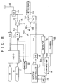
- FIG. 8 a digital portable telephone of the DTMA system is so constructed as shown in FIG. 8.
- FIG. 8 an embodiment of the present invention represented by such a digital portable telephone will be described.
- any component circuits or elements corresponding to those used in FIG. 2 are denoted by the same reference numerals, and a detailed explanation thereof is omitted.
- the error generation frequency when the error generation frequency is low in a digital audio signal or digital data transmitted from a base station, it can be presumed that the error generation frequency is low also in a digital audio signal or digital data transmitted from a portable telephone and received at the base station.
- processes of digital-to-analog conversion and time base correction are executed in an audio circuit 12.
- the output signal of the audio circuit 12 is partially supplied to a detecting circuit 51, which then extracts a BER signal S51 representing the bit error rate of the audio signal or data transmitted from the base station.
- the BER signal thus obtained is supplied to a comparator 52 as a parameter indicative of the reception state.
- a shaping circuit 53 outputs a signal S53 which indicates an allowable value of the bit error rate of the audio signal or data transmitted from the base station.
- the signal S53 is then supplied as a reference signal to the comparator 52.
- the signal S51 is compared with the reference signal S53, and the comparison output thereof is supplied to a system controller 21.
- the system controller 21 decides, in response to the comparison output of the comparator 52, the error generation frequency of the audio signal or data transmitted from the base station. If the error generation frequency is lower than the predetermined value indicated by the reference signal S53, the transmission output is set to an L mode. To the contrary, if the error generation frequency is higher than the predetermined value, the transmission output is set to an H mode. In case the error generation frequency is continuously kept to be less than the predetermined value for more than a preset period of time, then the transmission output is set to the L mode. And when the error generation frequency has exceeded the predetermined value, the transmission output is set immediately to the H mode.
- the processing sequence may be returned to step 113. It is also possible to use the reception-level detection voltage V41 as a signal indicating the logarithm of the reception level. Furthermore, an intermediate value between a great value (H mode) and a small value (L mode) may be prepared as another transmission output in addition thereto, and such transmission output may be changed in a multiplicity of steps. Besides the above, it is further possible in the system controller 21 to execute the processes of the circuits 51 to 53 by means of software. In this case also, similarly to the foregoing instances of FIGS. 6A, 6B, 7A and 7B, the transmission output can be switched to the L mode when there occurs no deterioration of the error rate for a predetermined period of time.
Landscapes
- Engineering & Computer Science (AREA)
- Computer Networks & Wireless Communication (AREA)
- Signal Processing (AREA)
- Mobile Radio Communication Systems (AREA)
- Transceivers (AREA)
- Transmitters (AREA)
Claims (7)
- Telekommunikationsvorrichtung mitwobei die Steuerschaltung (21) betreibbar ist, um den Ausgangspegel des von dem Verstärker (14) abgegebenen Übertragungssignals in Abhängigkeit des von der Erfassungsschaltung (41) abgegebenen Signals zu steuern,einer Empfangsschaltung (17) zum Empfang eines Signals welches von einer Gegenstation ausgesendet wurde,einer Sendeschaltung (13) zur Übertragung eines Signals zu der Gegenstation,einem Verstärker (14) zur Verstärkung des Signals, welches von der Sendeschaltung (13) übertragen werden soll,einer Steuerschaltung (21, 31, 32, 33) zur Steuerung des Pegels des von dem Verstärker (14) abgegebenen Übertragungssignals undeiner Erfassungsschaltung (41) zur Erfassung des Empfangsstatus eines von der Gegenstation empfangenen Signals,
dadurch gekennzeichnet,
daß der erfaßte Empfangsstatus die Fehlerrate des von der Gegenstation übertragenen Signals ist und daß die Steuerschaltung (21) betreibbar ist, den Pegel des Übertragungssignals auf einen niedrigen Wert innerhalb eines vorgegebenen Bereichs zu steuern, falls die Fehlerrate des von der Gegenstation übertragenen Signals einen festgesetzten Wert erfüllt. - Telekommunikationsvorrichtung nach Anspruch 1,
wobei die Steuerschaltung den Verstärker in Abhängigkeit des Erfassungsergebnisses der Erfassungsschaltung (51) in der Art steuert, daß der Pegel des Übertragungssignals innerhalb eines vorgegebenen Bereichs angehoben wird, wenn das Resultat der Erfassung besagt, daß die Fehlerrate des von der Gegenstation übertragenen Signals in dem Niederpegel-Modus einen festgesetzten Wert nicht erfüllt. - Telekommunikationsvorrichtung nach Anspruch 1 oder 2,
wobei die Steuerschaltung (21) betreibbar ist, den Ausgangspegel des Übertragungssignals selektiv von einem Hochpegel-Modus in einen Niederpegel-Modus oder von einem Niederpegel-Modus in einen Hochpegel-Modus zu schalten, in Übereinstimmung mit der Fehlerrate des von der Gegenstation übertragenen Signals. - Telekommunikationsvorrichtung nach einem der vorhergehenden Ansprüche,
wobei die Steuerschaltung (21) den Verstärker (14) in der Art steuert, daß der Ausgangspegel des von dem Verstärker (14) abgegebenen Übertragungssignals, für einen festgesetzten Zeitraum nach Aufnahme der Verbindung zu der Gegenstation, in dem Hochpegel-Modus festgehalten wird. - Telekommunikationsvorrichtung nach einem der vorhergehenden Ansprüche,
die zusätzlich eine Extrahierschaltung für die Extraktion von Daten aus dem Ausgangssignal der Empfangsschaltung enthält zur Steuerung des Übertragungspegels, wobei die Steuerschaltung (21) ausgebildet ist, den Übertragungspegel auf Grundlage der von dieser Extrahierschaltung extrahierten Daten zu steuern. - Telekommunikationsvorrichtung nach Anspruch 5, wobei die Steuerschaltung (21) ausgebildet ist, den Verstärker (14) in Abhängigkeit der von der Extrahierschaltung erhaltenen Daten so zu steuern, daß der Ausgangspegel des Übertragungssignals in einer Mehrzahl von Stufen stufenweise ausgegeben wird, und ferner den Verstärker in Abhängigkeit der von der Erfassungsschaltung erhaltenen Fehlerrate so zu steuern, daß der Ausgangspegel des Übertragungssignals innerhalb des vorgegebenen Bereichs auf eine niedrigere Stufe geschaltet wird, bezüglich jeder der Stufen.
- Telekommunikationsvorrichtung nach Anspruch 5 oder 6,
wobei die von der Extrahierschaltung extrahierten Daten einem MAC (Mobile Attenuation Code = Mobiler Dämpfungs Code) Signal entsprechen.
Applications Claiming Priority (3)
| Application Number | Priority Date | Filing Date | Title |
|---|---|---|---|
| JP5139096A JPH06326631A (ja) | 1993-05-17 | 1993-05-17 | 無線通信機 |
| JP139096/93 | 1993-05-17 | ||
| JP13909693 | 1993-05-17 |
Publications (2)
| Publication Number | Publication Date |
|---|---|
| EP0625833A1 EP0625833A1 (de) | 1994-11-23 |
| EP0625833B1 true EP0625833B1 (de) | 1999-07-14 |
Family
ID=15237405
Family Applications (1)
| Application Number | Title | Priority Date | Filing Date |
|---|---|---|---|
| EP94303324A Expired - Lifetime EP0625833B1 (de) | 1993-05-17 | 1994-05-09 | Sendeleistungssteuerung einer Mobil-Station in einem Mobil-Funktelefonsystem |
Country Status (5)
| Country | Link |
|---|---|
| US (1) | US5524287A (de) |
| EP (1) | EP0625833B1 (de) |
| JP (1) | JPH06326631A (de) |
| KR (1) | KR940027334A (de) |
| DE (1) | DE69419455T2 (de) |
Families Citing this family (21)
| Publication number | Priority date | Publication date | Assignee | Title |
|---|---|---|---|---|
| US5671218A (en) * | 1994-04-28 | 1997-09-23 | Lucent Technologies Inc. | Controlling power and access of wireless devices to base stations which use code division multiple access |
| JP3380036B2 (ja) * | 1994-05-20 | 2003-02-24 | 富士通株式会社 | 基地局および移動局における待受け制御方法 |
| US5737687A (en) * | 1995-03-01 | 1998-04-07 | Qualcomm Incorporated | Self-attenuating RF transceiver system using antenna and modem interfaces and cable link |
| US5689815A (en) * | 1995-05-04 | 1997-11-18 | Oki Telecom, Inc. | Saturation prevention system for radio telephone with open and closed loop power control systems |
| JP3098180B2 (ja) * | 1995-10-09 | 2000-10-16 | キヤノン株式会社 | コードレス電話システム |
| FI100072B (fi) * | 1996-01-19 | 1997-09-15 | Nokia Mobile Phones Ltd | Menetelmä lähetystehon säätämiseksi sekä radiojärjestelmä |
| KR100193842B1 (ko) * | 1996-09-13 | 1999-06-15 | 윤종용 | 무선통신시스템의 전력조절 회로 및 방법 |
| US5956619A (en) * | 1996-12-12 | 1999-09-21 | Globalstar L.P. | Satellite controlled power control for personal communication user terminals |
| JPH10190381A (ja) * | 1996-12-27 | 1998-07-21 | Fujitsu Ltd | 送受信装置 |
| US6236863B1 (en) | 1997-03-31 | 2001-05-22 | Oki Telecom, Inc. | Comprehensive transmitter power control system for radio telephones |
| SE9702272L (sv) * | 1997-06-13 | 1998-12-14 | Ericsson Telefon Ab L M | Anordning i en radioenhet |
| US6253092B1 (en) * | 1997-11-25 | 2001-06-26 | Uniden Financial, Inc. | Closed loop transmitter with DAC sensitivity adjusted to detector nonlinearity |
| FI106670B (fi) * | 1997-12-08 | 2001-03-15 | Nokia Networks Oy | Vastaanottomenetelmä ja vastaanotin |
| AUPP196598A0 (en) * | 1998-02-20 | 1998-03-19 | Siemens Plessey Electronic Systems Pty Ltd | Transmitter |
| KR100357619B1 (ko) * | 1998-06-23 | 2003-01-15 | 삼성전자 주식회사 | 이동 통신단말기의 출력전력 제어장치 및 방법 |
| KR100326929B1 (ko) * | 2000-01-28 | 2002-03-13 | 김형곤 | 원격제어 송신기의 송신출력 제어회로 |
| FR2813487B1 (fr) * | 2000-08-31 | 2002-11-29 | Cit Alcatel | Procede et dispositif de controle de l'amplification du signal emis par un terminal mobile permettant d'augmenter l'autonomie dudit terminal mobile |
| JP4564196B2 (ja) * | 2001-03-23 | 2010-10-20 | 株式会社東芝 | 無線通信装置および送信電力制御装置 |
| US6954620B2 (en) * | 2002-07-19 | 2005-10-11 | The Boeing Company | RF power control system including watchdog circuit |
| CN101777694B (zh) * | 2009-11-16 | 2012-10-03 | 福建省泉州华鸿通讯有限公司 | 一种对讲机大功率有源天线 |
| JP6115266B2 (ja) * | 2013-04-03 | 2017-04-19 | 株式会社デンソー | 通信装置 |
Family Cites Families (8)
| Publication number | Priority date | Publication date | Assignee | Title |
|---|---|---|---|---|
| DE3417233A1 (de) * | 1984-05-10 | 1985-11-14 | Standard Elektrik Lorenz Ag, 7000 Stuttgart | Funksystem |
| JPS63226124A (ja) * | 1986-10-29 | 1988-09-20 | Oki Electric Ind Co Ltd | 無線装置用レベル制御回路 |
| JPH02215238A (ja) * | 1989-02-15 | 1990-08-28 | Matsushita Electric Ind Co Ltd | 移動無線装置 |
| JP2769478B2 (ja) * | 1989-04-10 | 1998-06-25 | 三菱電機株式会社 | 無線機 |
| KR910007654B1 (ko) * | 1989-04-26 | 1991-09-28 | 삼성전자 주식회사 | 이동식 무선전화기의 rf전력 제어회로 |
| KR910007680B1 (ko) * | 1989-04-26 | 1991-09-30 | 삼성전자 주식회사 | 휴대용 이동 무선전화기의 rf 전력 레벨 제어회로 |
| US5129098A (en) * | 1990-09-24 | 1992-07-07 | Novatel Communication Ltd. | Radio telephone using received signal strength in controlling transmission power |
| DE69231437T2 (de) * | 1991-12-26 | 2001-03-01 | Nec Corp., Tokio/Tokyo | System zur Steuerung der Sendeleistung mit Gewährleistung einer konstanten Signalqualität in einem Mobilkommunikationsnetzwerk |
-
1993
- 1993-05-17 JP JP5139096A patent/JPH06326631A/ja active Pending
-
1994
- 1994-05-09 DE DE69419455T patent/DE69419455T2/de not_active Expired - Fee Related
- 1994-05-09 EP EP94303324A patent/EP0625833B1/de not_active Expired - Lifetime
- 1994-05-13 US US08/242,337 patent/US5524287A/en not_active Expired - Fee Related
- 1994-05-17 KR KR1019940010764A patent/KR940027334A/ko not_active Withdrawn
Also Published As
| Publication number | Publication date |
|---|---|
| DE69419455D1 (de) | 1999-08-19 |
| JPH06326631A (ja) | 1994-11-25 |
| DE69419455T2 (de) | 2000-01-05 |
| KR940027334A (ko) | 1994-12-10 |
| EP0625833A1 (de) | 1994-11-23 |
| US5524287A (en) | 1996-06-04 |
Similar Documents
| Publication | Publication Date | Title |
|---|---|---|
| EP0625833B1 (de) | Sendeleistungssteuerung einer Mobil-Station in einem Mobil-Funktelefonsystem | |
| US7634288B2 (en) | Mobile communication system, mobile communication terminal, power control method used therefor, and program therefor | |
| KR100277126B1 (ko) | 가변 전력 증폭기의 동적 조정 장치 및 방법 | |
| US5745842A (en) | Method and apparatus for controlling operation of a portable or mobile battery-operated radios | |
| KR100265527B1 (ko) | 다수의 정보 클래스를 전달하기 위한 무선 망에서의 전력 제어방법 | |
| JP3722055B2 (ja) | 携帯端末装置 | |
| US7218945B2 (en) | Transmission power controlling method and base station apparatus | |
| US5953646A (en) | System for controlling power consumption of a mobile radio communication device during standby using signal error rate | |
| US6445732B1 (en) | Dynamic range reduction circuitry for a digital communications receiver | |
| EP0626765A1 (de) | Funkkommunikationsgerät | |
| KR100366799B1 (ko) | 이동통신시스템의전송전력제어방법 | |
| JP2000252917A (ja) | セルラーシステム送信電力制御方法 | |
| KR100288358B1 (ko) | 셀룰러시스템에서순방향전력제어방법 | |
| KR100363358B1 (ko) | 소비전력절감장치 | |
| US6636724B1 (en) | Method for indoor operation of a wireless telecommunication device | |
| US7103336B1 (en) | Radio receiver, radio receiving method, and recording medium | |
| CA2024362C (en) | Transmitting power control circuit | |
| JP2943822B2 (ja) | 無線機の動作電圧制御回路 | |
| US7496337B2 (en) | Method for controlling LNA gain state | |
| KR19980025795A (ko) | 이동 통신 단말기용 통신 제어 방법 및 그 장치 | |
| US20030129947A1 (en) | Data communication terminal device and data communication rate varying method using the same | |
| KR100358434B1 (ko) | 아이에스-2000 씨디엠에이 이동통신 시스템의 역방향외부루프 전력제어방법 | |
| KR100591336B1 (ko) | 이동통신 단말기의 이득조정방법 | |
| JP3063891B2 (ja) | 携帯電話 | |
| JP2772890B2 (ja) | 移動無線電話機におけるチャンネル切換方式 |
Legal Events
| Date | Code | Title | Description |
|---|---|---|---|
| PUAI | Public reference made under article 153(3) epc to a published international application that has entered the european phase |
Free format text: ORIGINAL CODE: 0009012 |
|
| AK | Designated contracting states |
Kind code of ref document: A1 Designated state(s): DE GB IT |
|
| 17P | Request for examination filed |
Effective date: 19950425 |
|
| 17Q | First examination report despatched |
Effective date: 19970313 |
|
| GRAG | Despatch of communication of intention to grant |
Free format text: ORIGINAL CODE: EPIDOS AGRA |
|
| GRAG | Despatch of communication of intention to grant |
Free format text: ORIGINAL CODE: EPIDOS AGRA |
|
| GRAH | Despatch of communication of intention to grant a patent |
Free format text: ORIGINAL CODE: EPIDOS IGRA |
|
| GRAH | Despatch of communication of intention to grant a patent |
Free format text: ORIGINAL CODE: EPIDOS IGRA |
|
| GRAA | (expected) grant |
Free format text: ORIGINAL CODE: 0009210 |
|
| AK | Designated contracting states |
Kind code of ref document: B1 Designated state(s): DE GB IT |
|
| REF | Corresponds to: |
Ref document number: 69419455 Country of ref document: DE Date of ref document: 19990819 |
|
| ITF | It: translation for a ep patent filed | ||
| PLBE | No opposition filed within time limit |
Free format text: ORIGINAL CODE: 0009261 |
|
| STAA | Information on the status of an ep patent application or granted ep patent |
Free format text: STATUS: NO OPPOSITION FILED WITHIN TIME LIMIT |
|
| 26N | No opposition filed | ||
| PGFP | Annual fee paid to national office [announced via postgrant information from national office to epo] |
Ref country code: DE Payment date: 20010430 Year of fee payment: 8 |
|
| PGFP | Annual fee paid to national office [announced via postgrant information from national office to epo] |
Ref country code: GB Payment date: 20010509 Year of fee payment: 8 |
|
| REG | Reference to a national code |
Ref country code: GB Ref legal event code: IF02 |
|
| PG25 | Lapsed in a contracting state [announced via postgrant information from national office to epo] |
Ref country code: GB Free format text: LAPSE BECAUSE OF NON-PAYMENT OF DUE FEES Effective date: 20020509 |
|
| PG25 | Lapsed in a contracting state [announced via postgrant information from national office to epo] |
Ref country code: DE Free format text: LAPSE BECAUSE OF NON-PAYMENT OF DUE FEES Effective date: 20021203 |
|
| GBPC | Gb: european patent ceased through non-payment of renewal fee |
Effective date: 20020509 |
|
| PG25 | Lapsed in a contracting state [announced via postgrant information from national office to epo] |
Ref country code: IT Free format text: LAPSE BECAUSE OF NON-PAYMENT OF DUE FEES;WARNING: LAPSES OF ITALIAN PATENTS WITH EFFECTIVE DATE BEFORE 2007 MAY HAVE OCCURRED AT ANY TIME BEFORE 2007. THE CORRECT EFFECTIVE DATE MAY BE DIFFERENT FROM THE ONE RECORDED. Effective date: 20050509 |