EP0624834A2 - Einzel-Zyklus Positionniergerät - Google Patents
Einzel-Zyklus Positionniergerät Download PDFInfo
- Publication number
- EP0624834A2 EP0624834A2 EP94106420A EP94106420A EP0624834A2 EP 0624834 A2 EP0624834 A2 EP 0624834A2 EP 94106420 A EP94106420 A EP 94106420A EP 94106420 A EP94106420 A EP 94106420A EP 0624834 A2 EP0624834 A2 EP 0624834A2
- Authority
- EP
- European Patent Office
- Prior art keywords
- motor
- frequency
- power
- control means
- stop signal
- Prior art date
- Legal status (The legal status is an assumption and is not a legal conclusion. Google has not performed a legal analysis and makes no representation as to the accuracy of the status listed.)
- Granted
Links
Images


Classifications
-
- G—PHYSICS
- G05—CONTROLLING; REGULATING
- G05B—CONTROL OR REGULATING SYSTEMS IN GENERAL; FUNCTIONAL ELEMENTS OF SUCH SYSTEMS; MONITORING OR TESTING ARRANGEMENTS FOR SUCH SYSTEMS OR ELEMENTS
- G05B19/00—Programme-control systems
- G05B19/02—Programme-control systems electric
- G05B19/18—Numerical control [NC], i.e. automatically operating machines, in particular machine tools, e.g. in a manufacturing environment, so as to execute positioning, movement or co-ordinated operations by means of programme data in numerical form
- G05B19/416—Numerical control [NC], i.e. automatically operating machines, in particular machine tools, e.g. in a manufacturing environment, so as to execute positioning, movement or co-ordinated operations by means of programme data in numerical form characterised by control of velocity, acceleration or deceleration
-
- G—PHYSICS
- G05—CONTROLLING; REGULATING
- G05B—CONTROL OR REGULATING SYSTEMS IN GENERAL; FUNCTIONAL ELEMENTS OF SUCH SYSTEMS; MONITORING OR TESTING ARRANGEMENTS FOR SUCH SYSTEMS OR ELEMENTS
- G05B2219/00—Program-control systems
- G05B2219/30—Nc systems
- G05B2219/34—Director, elements to supervisory
- G05B2219/34217—Microprocessor with build in pwm
-
- G—PHYSICS
- G05—CONTROLLING; REGULATING
- G05B—CONTROL OR REGULATING SYSTEMS IN GENERAL; FUNCTIONAL ELEMENTS OF SUCH SYSTEMS; MONITORING OR TESTING ARRANGEMENTS FOR SUCH SYSTEMS OR ELEMENTS
- G05B2219/00—Program-control systems
- G05B2219/30—Nc systems
- G05B2219/41—Servomotor, servo controller till figures
- G05B2219/41101—Stop, halt step, ac motor on certain excitation phase, after sensing a reference
-
- G—PHYSICS
- G05—CONTROLLING; REGULATING
- G05B—CONTROL OR REGULATING SYSTEMS IN GENERAL; FUNCTIONAL ELEMENTS OF SUCH SYSTEMS; MONITORING OR TESTING ARRANGEMENTS FOR SUCH SYSTEMS OR ELEMENTS
- G05B2219/00—Program-control systems
- G05B2219/30—Nc systems
- G05B2219/41—Servomotor, servo controller till figures
- G05B2219/41285—Dynamic brake of ac, dc motor
-
- G—PHYSICS
- G05—CONTROLLING; REGULATING
- G05B—CONTROL OR REGULATING SYSTEMS IN GENERAL; FUNCTIONAL ELEMENTS OF SUCH SYSTEMS; MONITORING OR TESTING ARRANGEMENTS FOR SUCH SYSTEMS OR ELEMENTS
- G05B2219/00—Program-control systems
- G05B2219/30—Nc systems
- G05B2219/41—Servomotor, servo controller till figures
- G05B2219/41293—Inverter, dc-to-ac
-
- G—PHYSICS
- G05—CONTROLLING; REGULATING
- G05B—CONTROL OR REGULATING SYSTEMS IN GENERAL; FUNCTIONAL ELEMENTS OF SUCH SYSTEMS; MONITORING OR TESTING ARRANGEMENTS FOR SUCH SYSTEMS OR ELEMENTS
- G05B2219/00—Program-control systems
- G05B2219/30—Nc systems
- G05B2219/41—Servomotor, servo controller till figures
- G05B2219/41319—Ac, induction motor
-
- G—PHYSICS
- G05—CONTROLLING; REGULATING
- G05B—CONTROL OR REGULATING SYSTEMS IN GENERAL; FUNCTIONAL ELEMENTS OF SUCH SYSTEMS; MONITORING OR TESTING ARRANGEMENTS FOR SUCH SYSTEMS OR ELEMENTS
- G05B2219/00—Program-control systems
- G05B2219/30—Nc systems
- G05B2219/43—Speed, acceleration, deceleration control ADC
- G05B2219/43177—Single cycle positioning, start, move, stop for single rotation
Definitions
- This invention relates to positioning systems and, more particularly, to an improved single cycle positioning system which utilizes an induction motor to accurately position a cyclicly movable member at a precise location within its movement cycle according to the preamble of claim 1.
- Positioning systems utilizing servo motors are known. However, due to the type of motor required, such systems tend to be expensive. It is therefore another object of the present invention to provide a positioning system of the type described which utilizes a relatively inexpensive induction motor.
- a single cycle positioning system which utilizes a three phase wye connected induction motor and comprises a source of DC power, a movable member coupled to the motor for controlled cyclical movement thereby, means for providing a start signal to initiate movement of the member, means associated with the member for providing a stop signal when the member is at a predetermined position within its cycle of movement, and controllable inverter means connected between the source of DC power and the three phase windings of the motor for selectively providing connections between the DC power source and the three phase windings of the motor.
- control means which is coupled to receive the start signal and the stop signal for controlling the inverter means.
- the control means is effective in response to the start signal for controlling the inverter means so as to generate from the source of DC power three substantially sinusoidal phases of AC power which are applied to respective ones of the three phase windings of the motor.
- the control means is effective in response to the stop signal for controlling the inverter means to effect a dynamic braking of the motor so that the moveable member comes to rest at a desired position within a defined range of the predetermined position.
- control means is operative in response to the start signal for applying AC power to the motor at a frequency which increases up to a predetermined frequency, and thereafter maintaining the frequency of the AC power at the predetermined frequency until receipt of the stop signal.
- control means is operative in response to the stop signal for decreasing the frequency of the AC power applied to the motor down from the predetermined frequency.
- control means is effective to maintain the voltage applied to the motor at a predetermined value from receipt of the start signal until receipt of the stop signal.
- control means is effective after receipt of the stop signal to reduce the voltage applied to the motor relative to the predetermined value as a function of the ratio of the applied frequency to the predetermined frequency.
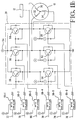
- Figures 1A and 1B together show a system for controlling a three phase wye connected induction motor 10 so that a movable member coupled thereto, illustratively the shaft 12, partakes of a single cycle of movement.
- a home switch 14 which is closed whenever the shaft 12 attains a predetermined angular orientation.
- the movable member is the shaft 12.
- the movable member can be any type of member which is controlled by the motor 10 for cyclical movement, such as, for example, a reciprocatory element.
- the home switch 14 is illustrated as being a simple single pole single throw switch, other types of switches may also be utilized as the home switch 14 such as, for example, a magnetic reed switch or a Hall effect sensing device.
- a coupling mechanism such as reduction gearing, between the motor 10 and the movable member 12 whereby the movable member 12 partakes of a single cycle of movement when the motor 10 makes some predetermined number of revolutions.
- Movement of the member 12 is initiated in response to closure of the switch 16 which may be, illustratively, a foot operated switch when the disclosed system is utilized in the environment of a crimping press of the general type disclosed in the aforereferenced U.S. Patent No. 3,343,398.
- Closure of the foot switch 16 results in the generation of a start signal on the lead 18 to the microprocessor 20 via the opto-isolator 22.
- closure of the home switch 14 results in the generation of a stop signal on the lead 24 to the microprocessor 20 via the opto-isolator 26.
- the microprocessor 20 responds to the start and stop signals on the leads 18 and 24, respectively, to control the three phase inverter 28 to supply power to the three phase windings 30, 32 and 34 of the motor 10 so that the shaft 12 partakes of a single revolution.
- the microprocessor 20 illustratively is a type 80C51FA microprocessor manufactured by Intel Corporation, which type of microprocessor has pulse width modulation capability built into it.
- the microprocessor 20 illustratively is a type 80C51FA microprocessor manufactured by Intel Corporation, which type of microprocessor has pulse width modulation capability built into it.
- several dedicated pulse width modulation registers three of which are utilized by the inventive system - one for each phase of the motor 10.
- Associated with each of those registers is a counter which is incremented by a clock.
- each of the registers and counters is 8 bits in length so that it contains a number from 0 through 255.
- the counter is configured so that in response to incoming clock pulses, it counts from 0 up to 255 and then rolls over to 0 again. At each clock pulse, the value that is in each register is compared to the count in the associated counter.
- each PWM output from the microprocessor 20 is a square wave whose duty cycle is determined by the value which had been pre-loaded into its associated register.
- the clock pulses utilized for the aforedescribed pulse width modulation are provided by the programmable timer 36.
- the timer 36 illustratively is a type 82C54 programmable counting array manufactured by Intel Corporation.
- the programmable feature of the timer 36 is the frequency at which the clock pulses are provided on the lead 38. This frequency is determined by signals provided from the microprocessor 20 on the leads 40.
- the aforedescribed PWM outputs from the microprocessor 20 appear on the leads 42, 44, and 46, for the three windings 30, 32 and 34, respectively, of the motor 10.
- the duty cycle square wave signals on the leads 42, 44 and 46 are utilized in conjunction with selection output signals on the leads 48, 50 and 52 to control the inverter 28.
- the inverter 28 is connected to a DC power supply 54, illustratively 170 volts, and to the three phase windings 30, 32 and 34 of the motor 10.
- the inverter 28 includes three pairs of transistors, one pair for each of the windings 30, 32 and 34.
- associated with the winding 30 is a high transistor 56 and a low transistor 58
- associated with the winding 32 is a high transistor 60 and a low transistor 62
- associated with the winding 34 is a high transistor 64 and a low transistor 66.
- Opto-isolators 68-1, 68-2, 68-3, 68-4, 68-5 and 68-6 are provided to isolate the high voltages in the inverter 28 from the low control voltages. These control voltages are provided on the leads 70, 72, 74, 76, 78 and 80. The signals on the leads 72, 76 and 80 control the high transistors 56, 60 and 64, respectively, and the signals on the leads 70, 74 and 78 control the low transistors 58, 62 and 66, respectively.
- the PWM output leads 42, 44 and 46 from the microprocessor 20 are connected to the router circuits 82-1, 82-2 and 82-3, respectively.
- the other inputs to the router circuits 82-1, 82-2 and 82-3 are the selection leads 48, 50 and 52, respectively, from the microprocessor 20.
- the signal on each of the selection leads 48, 50 and 52 determines which of the transistors in each pair for each winding (i.e., which of the transistors 56 and 58, which of the transistors 60 and 62, and which of the transistors 64 and 66) is turned on and the corresponding PWM output lead 42, 44 or 46 determines the conductive duty cycle.
- the microprocessor 20 in accordance with an internally stored program and data, utilizes its inherent pulse width modulation capability to provide appropriate signals on its pulse width modulation output leads 42, 44 and 46 and on its selection leads 48, 50 and 52 to control the inverter 28 so that three substantially sinusoidal phases of AC power are applied to the three phase windings 30, 32 and 34 of the motor 10 to cause it to go from an at rest condition in response to a start signal on the lead 18 so as to move the shaft 12 through a single revolution.
- the foregoing is accomplished according to the present invention by controlling the motor 10 to run in three stages. The first stage is the acceleration stage; the second stage is the run stage; and the third stage is the deceleration stage.
- the motor 10 is rated to be supplied with three phase AC power at a frequency of 60 Hertz. It has been found that to accelerate the motor it is better to gradually increase the frequency of the AC power up to 60 Hertz rather than to immediately apply power at 60 Hertz. The motor's running speed is more quickly attained in this matter.
- the frequency of the AC power applied to the motor 10 is gradually increased from 0 up to 60 Hertz. This is the acceleration stage. During the run stage, the frequency is maintained at 60 Hertz. The run stage terminates, and the deceleration stage begins, upon receipt of the stop signal on the lead 24 due to closure of the home switch 14.
- Induction motors can be dynamically braked by fixing the internal magnetic field in space. However, it has been found that more predictable stopping is achieved with dynamic braking if the deceleration is controlled by reducing the frequency of the power applied to the motor 10. However, while the increase in frequency relative to time during the acceleration stage is substantially linear, the decrease in frequency relative to time during the deceleration stage preferably is substantially parabolic, as shown in Figure 5. Generally, when an induction motor rated at a particular frequency is run at a lower frequency, the voltage is proportionately reduced. Thus, for example, if the motor 10 is a 60 Hertz 120 volts RMS motor running at 30 Hertz, it is conventional to reduce the voltage to 60 volts RMS.
- the voltage may not have to be reduced even though the frequency is less than the rated frequency. It is thought that this permits the motor 10 to come up to speed more quickly. However, during the deceleration stage, the motor voltage is reduced in proportion to the frequency.
- Figure 6A illustrates the overall operation of the system according to the present invention.
- the system enters the acceleration stage where the inverter 28 is controlled to supply power to the motor 10 at a frequency which increases to 60 Hertz.
- the system enters the run stage where the inverter 28 is controlled to supply power to the motor at 60 Hertz.
- the system remains in the run stage until the home switch 14 is operated.
- the system enters the deceleration stage where the inverter 28 is controlled to supply power to the motor 10 at a frequency which decreases while the voltage is reduced as a function of the frequency.
- the location of the home switch 14 relative to the stopping position of the shaft 12 is such that the deceleration stage causes the shaft 12 to stop within an acceptable tolerance of the desired position.
- the duty cycles of the signals on the PWM output leads 42, 44 and 46 are determined in accordance with the table of Figure 2 and the frequency of the power applied to the motor 10 is determined by the the frequency of the clock pulses on the lead 38 from the timer 36, as programmed by the signals on the leads 40.
- a pulse width modulation table with 24 ordered pulse width modulation (PWM) values. Each of those values is addressed in accordance with the value of a pointer, which can vary from 0 through 23.
- the PWM value determines duty cycle, and can vary from 0 to 255, with a value of 255 being equated with a 100% duty cycle.
- the microprocessor 20 sequences through the table of Figure 2 by decrementing the pointer value and Figure 3 is a curve showing the PWM value as a function of the pointer value.
- the PWM value is 115, which equates to a duty cycle of 45%.
- phase A i.e., the winding 30
- phase B the B pointer is decremented from 7 to 0 and the low transistor is turned on and pulse width modulated in a decreasing manner.
- phase C the C pointer is decremented from 23 to 16 and the low transistor is turned on and pulse width modulated in an increasing manner.
- phase A the A pointer is decremented from 7 to 0 and the high transistor is turned on and pulse width modulated in a decreasing manner.
- phase B the B pointer is decremented from 23 to 16 and the high transistor is turned on and pulse width modulated in an increasing manner.
- phase C the C pointer is decremented from 15 to 8 and the low transistor is turned on fully. This operation continues so as to generate the three substantially sinusoidal phases of AC power.
- the microprocessor 20 includes a pulse width modulation counter and several pulse width modulation registers, of which three are utilized.
- the counter In response to clock pulses on the lead 38 from the timer 36, the counter counts up from 0 to 255. In response to the next clock pulse the counter rolls over to 0 and at the same time generates an interrupt signal.
- the microprocessor 20 sets an initial pointer value for each of the three phases. Since the three phases must be offset by 120 degrees, the initial pointer values are staggered one third of the way through the table of Figure 2. Thus, illustratively, the initial pointer value for phase A may be 15, the initial pointer value for phase B may be 7, and the initial pointer value for phase C may be 23.
- the PWM counter At the same time that the initial pointer values are set, the PWM counter is set to one less than the value that causes an interrupt signal to be generated. Thus, the PWM counter is set to 255.
- Figure 6C illustrates, for one of the phases, how the pulse width modulation operates.
- the PWM counter is incremented. A check is made to see if the count is 0. If yes, then the interrupt signal is generated. In any case, the count is compared with the PWM value that is stored in the PWM register. If the count is greater than the PWM value, the transistor that had been on for that phase is turned off. If the count is not greater than the PWM value, then the selected transistor for that phase is controlled to be conductive.
- Figure 6D illustrates how the PWM value is obtained and placed in the PWM register. Upon the occurrence of an interrupt signal, the pointer is checked to see if it is 0.
- the pointer is 0, it is set to 24 and the other transistor of the pair for that phase is selected. Then the pointer is decremented. If the pointer had not been equal to 0, then it is merely decremented. The pointer is used to obtain the PWM value from the table of Figure 2. The PWM value is then placed in the PWM register.
- each cycle of the AC power is divided into 48 steps.
- Each of those 48 steps is itself subdivided into 256 parts and the selected transistor is turned on for as many of those parts out of the 256 as is determined by the PWM value placed in the PWM register.
- the foregoing pulse width modulation operation is unvarying during the running of the motor 10.
- One thing that does vary, however, is that during the acceleration stage, the frequency of the pulses from the timer 36 gradually increases up to a frequency which results in AC power at 60 Hertz being supplied to the motor 10.
- the frequency of the pulses from the timer 36 gradually increases up to a frequency which results in AC power at 60 Hertz being supplied to the motor 10.
- the microprocessor 20 provides signals to the timer 36 over the leads 40 to control this pulse rate.
- the pulse rate increases and during the deceleration stage the pulse rate decreases.
- the increase in frequency is linear and during the deceleration stage the decrease in frequency is parabolic.
- Another variable is the RMS voltage applied to the motor 10. This voltage may be constant during the acceleration stage and is constant during the run stage, but decreases during the deceleration stage. Accordingly, during the deceleration stage, the PWM values are reduced by a factor corresponding to the ratio of the frequency of the power applied to the motor 10 to the running frequency of 60 Hertz, thereby lowering the duty cycles and reducing the applied voltage.
Landscapes
- Engineering & Computer Science (AREA)
- Human Computer Interaction (AREA)
- Manufacturing & Machinery (AREA)
- Physics & Mathematics (AREA)
- General Physics & Mathematics (AREA)
- Automation & Control Theory (AREA)
- Control Of Ac Motors In General (AREA)
- Stopping Of Electric Motors (AREA)
Applications Claiming Priority (2)
| Application Number | Priority Date | Filing Date | Title |
|---|---|---|---|
| US52882 | 1993-04-26 | ||
| US08/052,882 US5449990A (en) | 1993-04-26 | 1993-04-26 | Single cycle positioning system |
Publications (3)
| Publication Number | Publication Date |
|---|---|
| EP0624834A2 true EP0624834A2 (de) | 1994-11-17 |
| EP0624834A3 EP0624834A3 (de) | 1998-04-08 |
| EP0624834B1 EP0624834B1 (de) | 2002-08-28 |
Family
ID=21980530
Family Applications (1)
| Application Number | Title | Priority Date | Filing Date |
|---|---|---|---|
| EP94106420A Expired - Lifetime EP0624834B1 (de) | 1993-04-26 | 1994-04-25 | Einzel-Zyklus Positionniergerät |
Country Status (4)
| Country | Link |
|---|---|
| US (1) | US5449990A (de) |
| EP (1) | EP0624834B1 (de) |
| JP (1) | JPH06351273A (de) |
| DE (1) | DE69431220T2 (de) |
Cited By (3)
| Publication number | Priority date | Publication date | Assignee | Title |
|---|---|---|---|---|
| US6927502B2 (en) | 2000-05-12 | 2005-08-09 | Aloys Wobben | Three-phase asynchronous motor driven azimuthal drive for wind power installations |
| US6945752B1 (en) | 1998-11-26 | 2005-09-20 | Aloys Wobben | Azimuthal driving system for wind turbines |
| EP1662138A1 (de) * | 2003-08-12 | 2006-05-31 | Nabtesco Corporation | Untersetzungsgetriebe zur verwendung in einer windnachführungsvorrichtung für eine windenergieerzeugungsvorrichtung, und windnachführungsverfahren und -vorrichtung für eine windenergieerzeugungsvorrichtung unter verwendung des untersetzungsgetriebes |
Families Citing this family (7)
| Publication number | Priority date | Publication date | Assignee | Title |
|---|---|---|---|---|
| FR2752111B1 (fr) * | 1996-07-30 | 1998-10-30 | Texas Instruments France | Procede et dispositif de commande d'onduleurs |
| AU4334699A (en) | 1998-06-05 | 1999-12-20 | Milwaukee Electric Tool Corporation | Braking and control circuit for electric power tools |
| US6310452B1 (en) | 2000-06-09 | 2001-10-30 | Tyco Electronics Corp | Single cycle positioning system utilizing a DC motor |
| DE60238484D1 (de) * | 2001-06-27 | 2011-01-13 | Depuy Products Inc | Minimalinvasives orthopädisches Gerät |
| US7308904B2 (en) * | 2004-11-12 | 2007-12-18 | Megtec Systems, Inc. | Electric gear motor drive for switching valve |
| RU2360354C1 (ru) * | 2007-12-04 | 2009-06-27 | Олег Анатольевич Буглаев | Вентильный электродвигатель |
| CN102011698B (zh) * | 2010-12-15 | 2013-09-04 | 北京金风科创风电设备有限公司 | 风力发电机偏航控制方法及系统 |
Citations (12)
| Publication number | Priority date | Publication date | Assignee | Title |
|---|---|---|---|---|
| FR2201165A1 (de) * | 1972-09-26 | 1974-04-26 | Peugeot & Renault | |
| US3815002A (en) * | 1973-05-29 | 1974-06-04 | Westinghouse Electric Corp | Braking circuit for alternating current induction motor |
| US3953778A (en) * | 1974-04-01 | 1976-04-27 | Texas Instruments Incorporated | Motion control system for an inductively controlled multi-phase motor |
| US4456865A (en) * | 1982-04-22 | 1984-06-26 | The Babcock & Wilcox Company | High torque servo positioner using 3 phase variable frequency constant torque controller |
| US4482853A (en) * | 1981-08-24 | 1984-11-13 | Reuland Electric Company | Composite control for soft start and dynamic braking of a three-phase induction motor |
| US4496891A (en) * | 1982-08-05 | 1985-01-29 | Canon Kabushiki Kaisha | Stepping motor control apparatus |
| WO1986003075A1 (en) * | 1984-11-13 | 1986-05-22 | Zycron Systems, Inc. | Microprocessor speed controller |
| EP0274212A1 (de) * | 1986-12-04 | 1988-07-13 | Hollingsworth (U.K.) Limited | Verfahren zum Anlassen und Anhalten einer Friktionsspinnmaschine |
| US4962976A (en) * | 1989-03-11 | 1990-10-16 | Sanken Electric Co., Ltd. | A.C. motor drive method and apparatus for precision positional control |
| EP0404350A2 (de) * | 1989-06-23 | 1990-12-27 | The Whitaker Corporation | Presse mit Steuerschaltungsanordnung |
| US5063337A (en) * | 1987-04-23 | 1991-11-05 | Jean Evin | Electric motor regulation to obtain desired speed curve |
| US5151637A (en) * | 1989-04-19 | 1992-09-29 | Hitachi, Ltd. | Deceleration apparatus for motor and drive circuit for use in motor deceleration apparatus or control apparatus for use in sewing machine |
Family Cites Families (6)
| Publication number | Priority date | Publication date | Assignee | Title |
|---|---|---|---|---|
| GB1050950A (de) * | 1964-10-15 | |||
| US3617837A (en) * | 1970-10-06 | 1971-11-02 | Honeywell Inc | Pulse actuated motor control circuit |
| JPS5635699A (en) * | 1979-08-31 | 1981-04-08 | Canon Inc | Driving system for pulse motor |
| US4250442A (en) * | 1979-10-04 | 1981-02-10 | Sperry Corporation | Stable synchronous drive system for gyroscope rotor |
| US4868479A (en) * | 1985-10-15 | 1989-09-19 | The Charles Stark Draper Laboratory, Inc. | Low loss permanent magnet motor |
| KR940009414B1 (ko) * | 1990-06-15 | 1994-10-13 | 미쓰비시덴키 가부시키가이샤 | 엘리베이터의 도어제어장치 |
-
1993
- 1993-04-26 US US08/052,882 patent/US5449990A/en not_active Expired - Lifetime
-
1994
- 1994-04-21 JP JP6107960A patent/JPH06351273A/ja active Pending
- 1994-04-25 DE DE69431220T patent/DE69431220T2/de not_active Expired - Lifetime
- 1994-04-25 EP EP94106420A patent/EP0624834B1/de not_active Expired - Lifetime
Patent Citations (12)
| Publication number | Priority date | Publication date | Assignee | Title |
|---|---|---|---|---|
| FR2201165A1 (de) * | 1972-09-26 | 1974-04-26 | Peugeot & Renault | |
| US3815002A (en) * | 1973-05-29 | 1974-06-04 | Westinghouse Electric Corp | Braking circuit for alternating current induction motor |
| US3953778A (en) * | 1974-04-01 | 1976-04-27 | Texas Instruments Incorporated | Motion control system for an inductively controlled multi-phase motor |
| US4482853A (en) * | 1981-08-24 | 1984-11-13 | Reuland Electric Company | Composite control for soft start and dynamic braking of a three-phase induction motor |
| US4456865A (en) * | 1982-04-22 | 1984-06-26 | The Babcock & Wilcox Company | High torque servo positioner using 3 phase variable frequency constant torque controller |
| US4496891A (en) * | 1982-08-05 | 1985-01-29 | Canon Kabushiki Kaisha | Stepping motor control apparatus |
| WO1986003075A1 (en) * | 1984-11-13 | 1986-05-22 | Zycron Systems, Inc. | Microprocessor speed controller |
| EP0274212A1 (de) * | 1986-12-04 | 1988-07-13 | Hollingsworth (U.K.) Limited | Verfahren zum Anlassen und Anhalten einer Friktionsspinnmaschine |
| US5063337A (en) * | 1987-04-23 | 1991-11-05 | Jean Evin | Electric motor regulation to obtain desired speed curve |
| US4962976A (en) * | 1989-03-11 | 1990-10-16 | Sanken Electric Co., Ltd. | A.C. motor drive method and apparatus for precision positional control |
| US5151637A (en) * | 1989-04-19 | 1992-09-29 | Hitachi, Ltd. | Deceleration apparatus for motor and drive circuit for use in motor deceleration apparatus or control apparatus for use in sewing machine |
| EP0404350A2 (de) * | 1989-06-23 | 1990-12-27 | The Whitaker Corporation | Presse mit Steuerschaltungsanordnung |
Cited By (4)
| Publication number | Priority date | Publication date | Assignee | Title |
|---|---|---|---|---|
| US6945752B1 (en) | 1998-11-26 | 2005-09-20 | Aloys Wobben | Azimuthal driving system for wind turbines |
| US6927502B2 (en) | 2000-05-12 | 2005-08-09 | Aloys Wobben | Three-phase asynchronous motor driven azimuthal drive for wind power installations |
| EP1662138A1 (de) * | 2003-08-12 | 2006-05-31 | Nabtesco Corporation | Untersetzungsgetriebe zur verwendung in einer windnachführungsvorrichtung für eine windenergieerzeugungsvorrichtung, und windnachführungsverfahren und -vorrichtung für eine windenergieerzeugungsvorrichtung unter verwendung des untersetzungsgetriebes |
| EP1662138A4 (de) * | 2003-08-12 | 2012-09-26 | Nabtesco Corp | Untersetzungsgetriebe zur verwendung in einer windnachführungsvorrichtung für eine windenergieerzeugungsvorrichtung, und windnachführungsverfahren und -vorrichtung für eine windenergieerzeugungsvorrichtung unter verwendung des untersetzungsgetriebes |
Also Published As
| Publication number | Publication date |
|---|---|
| US5449990A (en) | 1995-09-12 |
| DE69431220T2 (de) | 2003-04-17 |
| JPH06351273A (ja) | 1994-12-22 |
| EP0624834B1 (de) | 2002-08-28 |
| EP0624834A3 (de) | 1998-04-08 |
| DE69431220D1 (de) | 2002-10-02 |
Similar Documents
| Publication | Publication Date | Title |
|---|---|---|
| US5448141A (en) | Adjustable speed drive for residential applications | |
| EP0235074B1 (de) | Geschwindigkeitssteuerung für ein Scheibenwischersystem | |
| US3274471A (en) | Direct current motor with transistorized power supply | |
| US4746844A (en) | Control and operation of brushless continuous torque toroid motor | |
| EP0624834B1 (de) | Einzel-Zyklus Positionniergerät | |
| US4431953A (en) | Circuit for operating a synchronous motor from a dc supply | |
| EP0409952A1 (de) | Regelvorrichtung für einen reluktanzmotor | |
| EP0762625A1 (de) | Elektrischer Antrieb | |
| US6310452B1 (en) | Single cycle positioning system utilizing a DC motor | |
| US4353021A (en) | Control circuit for a pulse motor | |
| KR20020075565A (ko) | 왕복동식 압축기의 운전제어장치 | |
| KR100210083B1 (ko) | 스위치드 릴럭턴스 모터의 속도제어장치 | |
| EP0916179B1 (de) | Betätigungs- und regelverfahren und vorrichtung, insbesondere für synchrone, permanentmagnet-motoren | |
| US3457486A (en) | Speed-controlling device for d-c motors | |
| US4470001A (en) | Induction motor control | |
| US6140795A (en) | Variable speed control for AC induction motors | |
| US5835676A (en) | Motor driving apparatus | |
| KR0138780B1 (ko) | 직류 모터의 전류 방향 변환 제어 방법 | |
| US5959426A (en) | Circuit configuration for affecting the step frequency in the winding-current activation of stepping motor drives with chopped power output stages | |
| DE4413802C2 (de) | Verfahren und Vorrichtung zum Steuern der Drehzahl eines elektrischen Dreiphasen-Asynchronmotors | |
| GB2092401A (en) | Control apparatus for single phase AC induction motor | |
| Krishnan et al. | Design and performance of a microcontroller-based switched reluctance motor drive system | |
| US4488102A (en) | Electronic switch control method | |
| JP2560855B2 (ja) | プラシレスモータの駆動装置 | |
| EP0220814A2 (de) | Einrichtung und Verfahren für Schrittmotorstabilisierung |
Legal Events
| Date | Code | Title | Description |
|---|---|---|---|
| PUAI | Public reference made under article 153(3) epc to a published international application that has entered the european phase |
Free format text: ORIGINAL CODE: 0009012 |
|
| AK | Designated contracting states |
Kind code of ref document: A2 Designated state(s): DE FR GB IT NL |
|
| PUAL | Search report despatched |
Free format text: ORIGINAL CODE: 0009013 |
|
| AK | Designated contracting states |
Kind code of ref document: A3 Designated state(s): DE FR GB IT NL |
|
| RHK1 | Main classification (correction) |
Ipc: G05B 19/416 |
|
| 17P | Request for examination filed |
Effective date: 19981007 |
|
| 17Q | First examination report despatched |
Effective date: 19991130 |
|
| GRAG | Despatch of communication of intention to grant |
Free format text: ORIGINAL CODE: EPIDOS AGRA |
|
| GRAG | Despatch of communication of intention to grant |
Free format text: ORIGINAL CODE: EPIDOS AGRA |
|
| GRAH | Despatch of communication of intention to grant a patent |
Free format text: ORIGINAL CODE: EPIDOS IGRA |
|
| GRAH | Despatch of communication of intention to grant a patent |
Free format text: ORIGINAL CODE: EPIDOS IGRA |
|
| GRAA | (expected) grant |
Free format text: ORIGINAL CODE: 0009210 |
|
| AK | Designated contracting states |
Kind code of ref document: B1 Designated state(s): DE FR GB IT NL |
|
| PG25 | Lapsed in a contracting state [announced via postgrant information from national office to epo] |
Ref country code: NL Free format text: LAPSE BECAUSE OF FAILURE TO SUBMIT A TRANSLATION OF THE DESCRIPTION OR TO PAY THE FEE WITHIN THE PRESCRIBED TIME-LIMIT Effective date: 20020828 |
|
| REG | Reference to a national code |
Ref country code: GB Ref legal event code: FG4D |
|
| REF | Corresponds to: |
Ref document number: 69431220 Country of ref document: DE Date of ref document: 20021002 |
|
| ET | Fr: translation filed | ||
| NLV1 | Nl: lapsed or annulled due to failure to fulfill the requirements of art. 29p and 29m of the patents act | ||
| PLBE | No opposition filed within time limit |
Free format text: ORIGINAL CODE: 0009261 |
|
| STAA | Information on the status of an ep patent application or granted ep patent |
Free format text: STATUS: NO OPPOSITION FILED WITHIN TIME LIMIT |
|
| 26N | No opposition filed |
Effective date: 20030530 |
|
| PGFP | Annual fee paid to national office [announced via postgrant information from national office to epo] |
Ref country code: IT Payment date: 20090429 Year of fee payment: 16 Ref country code: FR Payment date: 20090417 Year of fee payment: 16 |
|
| PGFP | Annual fee paid to national office [announced via postgrant information from national office to epo] |
Ref country code: GB Payment date: 20090429 Year of fee payment: 16 |
|
| GBPC | Gb: european patent ceased through non-payment of renewal fee |
Effective date: 20100425 |
|
| REG | Reference to a national code |
Ref country code: FR Ref legal event code: ST Effective date: 20101230 |
|
| PGFP | Annual fee paid to national office [announced via postgrant information from national office to epo] |
Ref country code: DE Payment date: 20101102 Year of fee payment: 17 |
|
| PG25 | Lapsed in a contracting state [announced via postgrant information from national office to epo] |
Ref country code: GB Free format text: LAPSE BECAUSE OF NON-PAYMENT OF DUE FEES Effective date: 20100425 Ref country code: IT Free format text: LAPSE BECAUSE OF NON-PAYMENT OF DUE FEES Effective date: 20100425 |
|
| REG | Reference to a national code |
Ref country code: DE Ref legal event code: R119 Ref document number: 69431220 Country of ref document: DE |
|
| REG | Reference to a national code |
Ref country code: DE Ref legal event code: R119 Ref document number: 69431220 Country of ref document: DE |
|
| PG25 | Lapsed in a contracting state [announced via postgrant information from national office to epo] |
Ref country code: FR Free format text: LAPSE BECAUSE OF NON-PAYMENT OF DUE FEES Effective date: 20100430 |
|
| PG25 | Lapsed in a contracting state [announced via postgrant information from national office to epo] |
Ref country code: DE Free format text: LAPSE BECAUSE OF NON-PAYMENT OF DUE FEES Effective date: 20111031 |