EP0624746B1 - Shut-off valve - Google Patents
Shut-off valve Download PDFInfo
- Publication number
- EP0624746B1 EP0624746B1 EP94107132A EP94107132A EP0624746B1 EP 0624746 B1 EP0624746 B1 EP 0624746B1 EP 94107132 A EP94107132 A EP 94107132A EP 94107132 A EP94107132 A EP 94107132A EP 0624746 B1 EP0624746 B1 EP 0624746B1
- Authority
- EP
- European Patent Office
- Prior art keywords
- chamber
- sub
- piston
- valve
- shut
- Prior art date
- Legal status (The legal status is an assumption and is not a legal conclusion. Google has not performed a legal analysis and makes no representation as to the accuracy of the status listed.)
- Expired - Lifetime
Links
Images

Classifications
-
- F—MECHANICAL ENGINEERING; LIGHTING; HEATING; WEAPONS; BLASTING
- F16—ENGINEERING ELEMENTS AND UNITS; GENERAL MEASURES FOR PRODUCING AND MAINTAINING EFFECTIVE FUNCTIONING OF MACHINES OR INSTALLATIONS; THERMAL INSULATION IN GENERAL
- F16K—VALVES; TAPS; COCKS; ACTUATING-FLOATS; DEVICES FOR VENTING OR AERATING
- F16K31/00—Actuating devices; Operating means; Releasing devices
- F16K31/12—Actuating devices; Operating means; Releasing devices actuated by fluid
- F16K31/122—Actuating devices; Operating means; Releasing devices actuated by fluid the fluid acting on a piston
-
- F—MECHANICAL ENGINEERING; LIGHTING; HEATING; WEAPONS; BLASTING
- F16—ENGINEERING ELEMENTS AND UNITS; GENERAL MEASURES FOR PRODUCING AND MAINTAINING EFFECTIVE FUNCTIONING OF MACHINES OR INSTALLATIONS; THERMAL INSULATION IN GENERAL
- F16K—VALVES; TAPS; COCKS; ACTUATING-FLOATS; DEVICES FOR VENTING OR AERATING
- F16K47/00—Means in valves for absorbing fluid energy
Definitions
- the invention relates to a check valve which can be actuated pneumatically by a piston / cylinder arrangement.
- a pneumatically actuated passage valve with an inlet and outlet for a medium-containing valve housing is known, the passage of which is blocked or opened by a closure element at the valve seat.
- the closure element is actuated by a piston rod, which is displaceably guided in the cylinder and divides the cylinder into a first and a second partial chamber.
- the piston itself has a cavity that is open to the first partial chamber and into which a cylindrical projection projects, which receives a seal and at the same time reduces the dead volume of the first chamber.
- the invention has for its object to form a check valve of the type mentioned so that on the one hand a quick switching of the check valve is possible, but on the other hand excessive control forces on the piston in the opening direction of the valve are avoided when controlling high pressures.
- the volume displacement element considerably reduces the dead volume in the first chamber when the shut-off valve is closed. Since the closure element of the valve according to the invention is loaded in its closed position by the medium against the valve seat, a force acts on the piston in the direction of the valve seat via the piston rod. To open the valve, the entire force acting on the piston must be compensated for by building up a control pressure in the first chamber. After the closure element has been lifted off the sealing seat, an excess force arises on the piston, since the opposite force component generated by the pressure of the medium is eliminated. This usually leads to a strong acceleration of the piston at very high pressure of the medium.
- the flow conditions in the first partial chamber are favorably influenced by radially extending ribs provided on the displacement element. However, so that the ribs do not increase the dead volume in the first chamber, the contour of each rib essentially corresponds to the contour of the adjacent wall area of the cavity.
- those areas of the volume displacement element which are on the side facing away from the piston are correspondingly, i.e. complementary to the wall of the first sub-chamber.
- An additional amplification of the effect according to the invention achieve by a throttle element which is arranged between the first sub-chamber and an inlet on the cylinder and is provided for the introduction of a control medium into the first sub-chamber. This prevents the rapid pressure reduction in the first sub-chamber from being compensated for by an uncontrolled control medium after the initial phase of a switching process.
- a check valve 10 designed according to the invention is shown in cross section in the closed state.
- the check valve 10 consists essentially of a cylinder 12, a piston 14, a piston rod 16, a closure element 18 and a valve seat 20.
- the closure element 18 blocks a medium in the direction of flow S, which passes through an inlet channel 22 into the check valve 10 and when open Check valve 10 flows out again via an outlet channel 24.
- the input channel 22 and the output channel 24 are delimited by a valve housing 25 which is connected to the cylinder 12.
- the closure element 18 rests on the valve seat 20 and closes a passage 26 which is surrounded by the valve seat 20.
- the closure element 18 is fixedly connected to the piston 14 via the piston rod 16.
- Prestressed springs 28 and 30 press on the piston 14 in the direction of the closed position of the closure element 18.
- the closure element 18 is in the closed position of the closure element 18 via the piston 14 and the piston rod 16 by the springs 28 and 30 and by the pressure of the medium charged.
- the cylinder 12, the piston 14, the piston rod 16, the closure element 18 and the springs 28 and 30 are arranged coaxially.
- the piston 14 is bell-shaped, so that there is a cavity 32 within the piston 14.
- the piston 14 divides the cylinder 12 into a first partial chamber 34 and a second partial chamber 36.
- the cavity 32 is open in the direction of the first partial chamber 34.
- the first sub-chamber 34 has a small dead volume when the shut-off valve 10 is closed, while the second sub-chamber 36 has an increased volume.
- a first connection circuit 38 is provided for the first subchamber 34 and a second 40 for the second subchamber 36.
- the piston 14 is moved to open or close the check valve 10 by appropriately setting a gas pressure in the first sub-chamber 34 or the second sub-chamber 36.
- the gas is moved into and out of the first and second subchambers 34, 36 by known devices for controlling the piston 14. A detailed description of these known devices is not necessary.
- a throttle 39, 41 is provided in the manner of a thin bore, which flows into the subchamber 34, 36 too quickly or flows too quickly out of the subchamber 34, 36 prevented.
- the throttle 39, 41 is matched to the volume reduction effect according to the invention in the first sub-chamber 34 when the check valve 10 is opened.
- a closure cap 42 is screwed onto the cylinder 12 and has an annular extension which extends in the direction of the piston 14 and serves as a stop 44 for the piston 14. Furthermore, the closure cap 42 has grooves 421, 422 into which the springs 28 and 30, which load the piston 14 in the closed position of the closure element 18, engage. As a result, the springs 28, 30 in the piston 14 are secured against radial movement relative to the closure cap 42.
- a seal 46 is provided in an annular groove 142 open radially outward in the piston 14.
- a volume displacement element 48 is introduced into the first partial chamber 34.
- the volume displacement element 48 is mounted coaxially to the piston rod 16, the piston rod 16 being axially displaceable relative to the volume displacement element 48.
- the volume displacement element 48 has a sleeve-shaped part 481 and a disk-shaped part 482.
- the sleeve-shaped part 481 protrudes into the cavity 32 of the piston 14.
- the disk-shaped part 482 adjoins the sleeve-shaped part 481 and extends to the wall of the cylinder 12, which radially delimits the first partial chamber 34.
- the disk-shaped part 482 is designed to match the contour of the cylinder wall and the surface contour of the inner end face of the first partial chamber 34.
- ribs 483 which are offset by 90 ° protrude from the sleeve-shaped part 481 of the volume displacement element 48.
- the shape of these ribs 483 is adapted to the adjacent areas of the cavity 32 of the piston 14.
- the dead volume that is to say the volume available for the control pressure when the shut-off valve 10 is closed in the first partial chamber 34, is greatly reduced by the volume displacement element 48.
- a control pressure is built up in the first subchamber 34, that is to say in the dead volume, by supplying compressed air to the first subchamber 34 through the connection 38, for example.
- the piston 14 and thus the piston rod 16 moves with the closure element 18 upwards .
- the volume in the first sub-chamber 34 increases greatly in relation to the initial volume, so that the control pressure which was necessary for the initial movement of the piston 14 is reduced correspondingly quickly. Since the actuating force in the opening direction is now greatly reduced, an excessive, sudden acceleration of the piston 14 is avoided.
Description
Die Erfindung betrifft ein Sperrventil, das durch eine Kolben/Zylinderanordnung pneumatisch betätigbar ist.The invention relates to a check valve which can be actuated pneumatically by a piston / cylinder arrangement.
Aus der DE-A-1 809 448, die den nächstkommenden Stand der Technik bildet, ist ein pneumatisch betätigbares Durchgangsventil mit einem Zu- und Ablauf für ein Medium enthaltendes Ventilgehäuse bekannt, dessen Durchgang beim Ventilsitz von einem Verschlußelement gesperrt oder geöffnet wird. Das Verschlußelement wird durch den in dem Zylinder verschiebbar geführten, den Zylinder in eine erste und eine zweite Teilkammer teilenden Kolben über eine Kolbenstange betätigt. Der Kolben selbst weist eine zur ersten Teilkammer offene Höhlung auf, in die ein zylindrischer Ansatz ragt, der eine Dichtung aufnimmt und zugleich das Totvolumen der ersten Kammer reduziert. An der Kolbenrückseite liegt eine Feder an, die den Kolben in die Schließstellung drückt.From DE-A-1 809 448, which forms the closest prior art, a pneumatically actuated passage valve with an inlet and outlet for a medium-containing valve housing is known, the passage of which is blocked or opened by a closure element at the valve seat. The closure element is actuated by a piston rod, which is displaceably guided in the cylinder and divides the cylinder into a first and a second partial chamber. The piston itself has a cavity that is open to the first partial chamber and into which a cylindrical projection projects, which receives a seal and at the same time reduces the dead volume of the first chamber. There is a spring on the back of the piston that pushes the piston into the closed position.
Aus der US-A-3 029 061 ist ein hydraulisches Ventil mit einem Kolben bekannt, der eine zu einer ersten Teilkammer hin offene Höhlung aufweist, in die ein Gehäusevorsprung ragt. Auch bei diesem Ventil wird der Kolben durch eine Feder in eine Grundstellung gedrückt, wobei aber kein mit dem Kolben über eine Kolbenstange verbundenes Verschlußelement vorgesehen ist.From US-A-3 029 061 a hydraulic valve with a piston is known which has a cavity which is open towards a first partial chamber and into which a housing projection projects. In this valve, too, the piston is pressed into a basic position by a spring, but there is no closure element connected to the piston via a piston rod.
Der Erfindung liegt die Aufgabe zugrunde, ein Sperrventil der eingangs angegebenen Art so auszubilden, daß einerseits ein schnelles Schalten des Sperrventils möglich ist, andererseits aber bei Steuerung hoher Drücke übermäßig große Stellkräfte am Kolben in Öffnungsrichtung des Ventils vermieden werden.The invention has for its object to form a check valve of the type mentioned so that on the one hand a quick switching of the check valve is possible, but on the other hand excessive control forces on the piston in the opening direction of the valve are avoided when controlling high pressures.
Diese Aufgabe wird erfindungsgemäß durch die Merkmale des Anspruchs 1 gelöst.This object is achieved by the features of claim 1.
Zweckmäßige Weiterbildungen der Erfindung sind in den abhängigen Ansprüchen beschrieben.Appropriate developments of the invention are described in the dependent claims.
Das Volumenverdrängungselement reduziert bei geschlossenem Sperrventil das Totvolumen in der ersten Kammer erheblich. Da das Verschlußelement des erfindungsgemäßen Ventils in seiner Schließstellung durch das Medium gegen den Ventilsitz belastet wird, wirkt über die Kolbenstange eine Kraft auf den Kolben in Richtung des Ventilsitzes. Zum Öffnen des Ventils ist die gesamte auf den Kolben wirkende Kraft durch den Aufbau eines Steuerdrucks in der ersten Kammer zu kompensieren. Nach dem Abheben des Verschlußelements von dem Dichtsitz entsteht am Kolben ein Kräfteüberschuß, da die durch den Druck des Mediums erzeugte, entgegengesetzte Kraftkomponente entfällt. Dies führt üblicherweise bei sehr hohem Druck des Mediums zu einer starken Beschleunigung des Kolbens. Durch das geringe Volumen der ersten Teilkammer bei geschlossenem Sperrventil fällt der Steuerdruck in der ersten Teilkammer während der Öffnungsbewegung des Kolbens schnell ab, so daß sich eine Beschädigung des Sperrventils praktisch ausschließen läßt, obwohl in der Anfangsphase des Schaltvorgangs des Sperrventils der volle Steuerdruck zur Verfügung steht. Der schnelle Druckabfall nach Ablauf der Anfangsphase bewirkt also keine Erhöhung der erforderlichen Schaltzeit. Die Strömungsverhältnisse in der ersten Teilkammer werden durch am Verdrängungselement vorgesehene, radial verlaufende Rippen günstig beeinflußt. Damit die Rippen jedoch das Totvolumen in der ersten Kammer nicht erhöhen, entspricht die Kontur jeder Rippe im wesentlichen der Kontur des angrenzenden Wandungsbereichs der Höhlung.The volume displacement element considerably reduces the dead volume in the first chamber when the shut-off valve is closed. Since the closure element of the valve according to the invention is loaded in its closed position by the medium against the valve seat, a force acts on the piston in the direction of the valve seat via the piston rod. To open the valve, the entire force acting on the piston must be compensated for by building up a control pressure in the first chamber. After the closure element has been lifted off the sealing seat, an excess force arises on the piston, since the opposite force component generated by the pressure of the medium is eliminated. This usually leads to a strong acceleration of the piston at very high pressure of the medium. Due to the small volume of the first sub-chamber when the shut-off valve is closed, the control pressure in the first sub-chamber drops rapidly during the opening movement of the piston, so that damage to the shut-off valve can be practically ruled out, although the full control pressure is available in the initial phase of the switching operation of the shut-off valve . The rapid drop in pressure after the end of the initial phase does not increase the required switching time. The flow conditions in the first partial chamber are favorably influenced by radially extending ribs provided on the displacement element. However, so that the ribs do not increase the dead volume in the first chamber, the contour of each rib essentially corresponds to the contour of the adjacent wall area of the cavity.
Bei einer bevorzugten Ausführungsform werden diejenigen Bereiche des Volumenverdrängungselements, die auf der den Kolben abgewandten Seite liegen, entsprechend, d.h. komplementär der Wandung der ersten Teilkammer ausgebildet.In a preferred embodiment, those areas of the volume displacement element which are on the side facing away from the piston are correspondingly, i.e. complementary to the wall of the first sub-chamber.
Eine zusätzliche Verstärkung des erfindungsgemäßen Effekts läßt sich durch ein Drosselelement erzielen, das zwischen der ersten Teilkammer und einem Einlaß am Zylinder angeordnet ist und für das Einleiten eines Steuermediums in die erste Teilkammer vorgesehen ist. Hierdurch wird vermieden, daß nach der Anfangsphase eines Schaltvorgangs durch ein unkontrolliert nachströmendes Steuermedium der schnelle Druckabbau in der ersten Teilkammer ausgeglichen wird.An additional amplification of the effect according to the invention achieve by a throttle element which is arranged between the first sub-chamber and an inlet on the cylinder and is provided for the introduction of a control medium into the first sub-chamber. This prevents the rapid pressure reduction in the first sub-chamber from being compensated for by an uncontrolled control medium after the initial phase of a switching process.
Weitere Merkmale und Vorteile der Erfindung ergeben sich aus der folgenden Beschreibung einer Ausführungsform der Erfindung unter Bezugnahme auf die Zeichnungen. Es zeigen:
- Fig. 1 eine Querschnittsansicht einer Ausführungsform der Erfindung; und
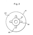
- Fig. 2 eine Draufsicht auf ein Volumenverdrängungselement der Ausführungsform von Fig. 1.
- 1 is a cross-sectional view of an embodiment of the invention; and
- FIG. 2 shows a top view of a volume displacement element of the embodiment from FIG. 1.
In Fig. 1 ist ein erfindungsgemäß ausgebildetes Sperrventil 10 im geschlossenen Zustand im Querschnitt dargestellt. Das Sperrventil 10 besteht im wesentlichen aus einem Zylinder 12, einem Kolben 14, einer Kolbenstange 16, einem Verschlußelement 18 und einem Ventilsitz 20. Das Verschlußelement 18 blockiert ein Medium in Fließrichtung S, das durch einen Eingangskanal 22 in das Sperrventil 10 gelangt und bei geöffnetem Sperrventil 10 über einen Ausgangskanal 24 wieder herausströmt. Der Eingangskanal 22 und der Ausgangskanal 24 werden durch ein Ventilgehäuse 25 begrenzt, das mit dem Zylinder 12 verbunden ist.In Fig. 1, a
Das Verschlußelement 18 liegt auf dem Ventilsitz 20 auf und verschließt einen Durchgang 26, der von dem Ventilsitz 20 umgeben wird. Das Verschlußelement 18 ist über die Kolbenstange 16 mit dem Kolben 14 fest verbunden. Auf den Kolben 14 drücken vorgespannte Federn 28 und 30 in Richtung auf die Schließstellung des Verschlußelements 18. Somit wird das Verschlußelement 18 über den Kolben 14 und die Kolbenstange 16 durch die Federn 28 und 30 sowie durch den anliegenden Druck des Mediums in Schließstellung des Verschlußelements 18 belastet.The
Der Zylinder 12, der Kolben 14, die Kolbenstange 16, das Verschlußelement 18 sowie die Federn 28 und 30 sind koaxial angeordnet.The
Der Kolben 14 ist glockenförmig ausgebildet, so daß sich eine Höhlung 32 innerhalb des Kolbens 14 ergibt. Der Kolben 14 teilt den Zylinder 12 in eine erste Teilkammer 34 und eine zweite Teilkammer 36. Die Höhlung 32 ist in Richtung auf die erste Teilkammer 34 geöffnet. Die erste Teilkammer 34 weist im geschlossenen Zustand des Sperrventils 10 ein kleines Totvolumen auf, während die zweite Teilkammer 36 ein vergrößertes Volumen aufweist.The
Um den Kolben 14 für eine Öffnungs- und Schließbewegung des Verschlußelements 18 steuern zu können, sind ein erster Anschluß schluß 38 für die erste Teilkammer 34 und ein zweiter 40 für die zweite Teilkammer 36 vorgesehen. Durch entsprechende Einstellung eines Gasdrucks in der ersten Teilkammer 34 bzw. der zweiten Teilkammer 36 wird der Kolben 14 zum Öffnen bzw. Schließen des Sperrventils 10 bewegt. Das Gas wird durch bekannte Vorrichtungen zum Steuern des Kolbens 14 in die bzw. aus der ersten und zweiten Teilkammer 34, 36 hinein bzw. heraus bewegt. Eine ausführliche Beschreibung dieser bekannten Vorrichtungen erübrigt sich. Zwischen dem Anschluß 38, 40 und der entsprechenden Teilkammer 34, 36 ist jeweils eine Drossel 39, 41 in der Art einer dünnen Bohrung vorgesehen, die ein zu schnelles Einströmen strömen in die Teilkammer 34, 36 bzw. ein zu schnelles aus der Teilkammer 34, 36 verhindert. Die Drossel 39, 41 ist dabei auf den erfindungsgemäßen Volumenreduzierungseffekt in der ersten Teilkammer 34 beim Öffnen des Sperrventils 10 abgestimmt.In order to be able to control the
Auf den Zylinder 12 ist eine Verschlußkappe 42 aufgeschraubt, die einen sich in Richtung auf den Kolben 14 erstreckenden ringförmigen Ansatz aufweist, der als Anschlag 44 für den Kolben 14 dient. Weiterhin weist die Verschlußkappe 42 Nuten 421, 422 auf, in die die den Kolben 14 in Schließstellung des Verschlußelements 18 belastenden Federn 28 und 30 eingreifen. Dadurch sind die Federn 28, 30 im Kolben 14 gegen eine Radialbewegung relativ zur Verschlußkappe 42 gesichert.A
Die anderen Enden der Federn 28 und 30 liegen auf der zum Anschlag 44 gerichteten Fläche des Kolbens 14 auf. Dabei drückt die radial innere Feder 30 gegen einen gegenüber dem Ende der Feder 28 erhöhten Absatz 141.The other ends of the
Um eine exakte, verlustfreie Steuerung des Kolbens 14 zu ermöglichen, ist in einer radial nach außen offenen Ringnut 142 im Kolben 14 eine Dichtung 46 vorgesehen.In order to enable precise, loss-free control of the
In die erste Teilkammer 34 ist ein Volumenverdrängungselement 48 eingebracht. Das Volumenverdrängungselement 48 ist koaxial zur Kolbenstange 16 gelagert, wobei die Kolbenstange 16 relativ zu dem Volumenverdrängungselement 48 axial verschiebbar ist. Das Volumenverdrängungselement 48 weist einen hülsenförmigen Teil 481 und einen scheibenförmigen Teil 482 auf. Der hülsenförmige Teil 481 ragt in die Höhlung 32 des Kolbens 14 hinein. Der scheibenförmige Teil 482 schließt sich an den hülsenförmigen Teil 481 an und erstreckt sich bis zur Wandung des Zylinders 12, die die erste Teilkammer 34 radial begrenzt. Der scheibenförmige Teil 482 ist der Kontur der Zylinderwandung und der Oberflächenkontur der Innenstirnfläche der ersten Teilkammer 34 angepaßt ausgebildet.A
Wie den Figuren 1 und 2 zu entnehmen ist, stehen von dem hülsenförmigen Teil 481 des Volumenverdrängungselements 48 um 90° versetzte Rippen 483 ab. Diese Rippen 483 sind in ihrer Kontur den angrenzenden Bereichen der Höhlung 32 des Kolbens 14 angepaßt ausgebildet. Durch das Volumenverdrängungselement 48 wird das Totvolumen, also das für den Steuerdruck bei geschlossenem Sperrventil 10 in der ersten Teilkammer 34 zur Verfügung stehende Volumen, stark verkleinert.As can be seen in FIGS. 1 and 2,
Zum Öffnen des Sperrventils 10 wird in der ersten Teilkammer 34, also in dem Totvolumen, ein Steuerdruck aufgebaut, indem durch den Anschluß 38 z.B. Druckluft der ersten Teilkammer 34 zugeführt wird. Ist die durch den Steuerdruck in der ersten Teilkammer 34 erzeugte Stellkraft größer als die Summe der Kräfte, die durch die Federn 28, 30 auf den Kolben 14 und durch den Mediumdruck auf das Verschlußelement 18 einwirken, so bewegt sich der Kolben 14 und somit die Kolbenstange 16 mit dem Verschlußelement 18 nach oben. Durch das Abheben des Verschlußelements 18 von dem Ventilsitz 20 entfällt plötzlich die zuvor durch den Druck des Mediums erzeugte Kraftkomponente in Schließrichtung. Durch die Bewegung des Kolbens 14 nach oben vergrößert sich aber das Volumen in der ersten Teilkammer 34 im Verhältnis zum Ausgangsvolumen stark, so daß der Steuerdruck, der für die Anfangsbewegung des Kolbens 14 nötig war, entsprechend schnell reduziert wird. Da nun die Stellkraft in Öffnungsrichtung stark vermindert ist, wird eine zu hohe, plötzliche Beschleunigung des Kolbens 14 vermieden.To open the shut-off
Claims (5)
- A shut-off valve (10), which can be pneumatically operated by a piston/cylinder arrangement (12, 14), having an inlet and outlet duct (22, 24) for a valve housing (25) containing medium, the passage (26) of which at the valve seat (20) is closed or opened by a sealing element (18), which is operated by the piston (14), which is displaceably guided in the cylinder (12) and divides the cylinder (12) into a first (34) and a second sub-chamber (36), via a piston rod (16) and in its closed position is loaded by the medium against the valve seat (20), wherein the piston (14) has a cavity (32) open to the first sub-chamber (34), into which a volume displacement element (48) in the first sub-chamber (34) extends, which to open the sealing element (18) has a higher pressure in comparison with the second sub-chamber (36), and with the shut-off valve (10) closed at least considerably reduces the clearance volume of the first sub-chamber (34), wherein the volume displacement element (48) has radially extending ribs (483), the contour of which substantially corresponds to the contour of the adjacent wall region of the cavity (32), and wherein the sealing element (18) is moved by controlling the pressure at least in the first sub-chamber (34).
- A shut-off valve according to Claim 1, wherein the volume displacement element (48) is disposed coaxially to the piston rod (16).
- A shut-off valve according to one of the preceding Claims, wherein the regions of the volume displacement element (48) which abut the wall limiting the first sub-chamber (34) have, on their side faced away from the piston (14), a contour which has a complementary construction to the contour of this wall.
- A shut-off valve according to one of the preceding Claims, wherein the volume displacement element (48) is prevented from making a movement relative to the cylinder (12) in the first sub-chamber (34).
- A shut-off valve having a connection (38, 40) for a pneumatic control medium for the first and/or second sub-chamber (34, 36) according to one of the preceding claims, wherein a choke (39) is provided between the first sub-chamber (34) and the connection (38) and/or a choke (41) is provided between the second sub-chamber (36) and the connection (40).
Applications Claiming Priority (2)
| Application Number | Priority Date | Filing Date | Title |
|---|---|---|---|
| DE9307166U DE9307166U1 (en) | 1993-05-11 | 1993-05-11 | |
| DE9307166U | 1993-05-11 |
Publications (3)
| Publication Number | Publication Date |
|---|---|
| EP0624746A2 EP0624746A2 (en) | 1994-11-17 |
| EP0624746A3 EP0624746A3 (en) | 1995-02-22 |
| EP0624746B1 true EP0624746B1 (en) | 1997-07-16 |
Family
ID=6893158
Family Applications (1)
| Application Number | Title | Priority Date | Filing Date |
|---|---|---|---|
| EP94107132A Expired - Lifetime EP0624746B1 (en) | 1993-05-11 | 1994-05-06 | Shut-off valve |
Country Status (2)
| Country | Link |
|---|---|
| EP (1) | EP0624746B1 (en) |
| DE (2) | DE9307166U1 (en) |
Families Citing this family (5)
| Publication number | Priority date | Publication date | Assignee | Title |
|---|---|---|---|---|
| DE19641073C2 (en) * | 1996-10-04 | 2000-07-13 | Adolf Harald Sonnleitner | Pressure-operated valve |
| DE19932743C2 (en) * | 1999-07-14 | 2003-10-09 | Thomas Scholzen | Control valve system with pneumatic actuator |
| DE10336065A1 (en) * | 2003-08-06 | 2005-03-03 | Bürkert Werke GmbH & Co. KG | Pneumatic valve drive |
| DE202006007591U1 (en) * | 2006-05-12 | 2007-06-21 | Bopp & Reuther Messtechnik Gmbh | Fluid control valve use in flow measurement has a volume for pressure compensation |
| CN113202967B (en) * | 2021-04-30 | 2022-10-04 | 中国空气动力研究与发展中心设备设计与测试技术研究所 | Ultralow temperature switch valve for low temperature wind tunnel |
Family Cites Families (3)
| Publication number | Priority date | Publication date | Assignee | Title |
|---|---|---|---|---|
| DE1074940B (en) * | 1960-02-04 | LICENTIA Patent-Verwaltungs-G.m.b.H., Frankfurt/M | Hydraulic drive for quick-closing valves | |
| US3029061A (en) * | 1959-07-16 | 1962-04-10 | Don R Hoxworth | Air-hydraulic control unit |
| DE1809448A1 (en) * | 1968-11-18 | 1970-06-11 | Edmund Pietrowski | Pneumatically operated straight-way valve |
-
1993
- 1993-05-11 DE DE9307166U patent/DE9307166U1/de not_active Expired - Lifetime
-
1994
- 1994-05-06 EP EP94107132A patent/EP0624746B1/en not_active Expired - Lifetime
- 1994-05-06 DE DE59403357T patent/DE59403357D1/en not_active Expired - Lifetime
Also Published As
| Publication number | Publication date |
|---|---|
| EP0624746A2 (en) | 1994-11-17 |
| DE9307166U1 (en) | 1993-07-15 |
| EP0624746A3 (en) | 1995-02-22 |
| DE59403357D1 (en) | 1997-08-21 |
Similar Documents
| Publication | Publication Date | Title |
|---|---|---|
| DE3523917A1 (en) | CONTROL VALVE ACTUATED BY A CONTROL BODY | |
| EP1435028B1 (en) | Pressure regulating valve, in particular proportional pressure regulating valve | |
| DE3305092C2 (en) | ||
| EP1525144B1 (en) | Pressure control valve | |
| DE3329790A1 (en) | Valve support for piston compressors | |
| EP0223935B1 (en) | Double circuit controlled brake pressure control valve | |
| EP0624746B1 (en) | Shut-off valve | |
| LU84377A1 (en) | ADJUSTABLE THROTTLE VALVE | |
| DE3322912A1 (en) | Multi-way seat valve | |
| DE4201442A1 (en) | Electronically controlled, directly actuated 3-way pressure regulating valve for gaseous and liquid media | |
| EP1440225A2 (en) | Hydraulic actuator for a gas exchange valve | |
| DE3311816C1 (en) | Pressure relief valve for air brake systems of motor vehicles | |
| EP0123866B1 (en) | Air pressure cylinder, especially an air pressure brake cylinder | |
| EP0975856A1 (en) | Hydraulic control device for at least one lift valve | |
| EP0483585B1 (en) | Adjustable proportional throttle valve with feedback | |
| EP0147589A2 (en) | Force actuated pressure control valve | |
| EP0289712A2 (en) | Pressure regulating valve | |
| WO2004109124A1 (en) | Proportional pressure control valve | |
| DE4129774A1 (en) | Pressure compensated switch valve for hydraulic media - is very compact with drive element compensated in itself independently of operating rod | |
| DE19626323B4 (en) | Safety valve device | |
| EP0312718B1 (en) | Double circuit controlled brake pressure control valve | |
| EP0702639B1 (en) | Servo-assisted steering system | |
| DE3639149C2 (en) | Brake force control device that can be controlled depending on the load | |
| EP0790544A1 (en) | Volumetric flow control device | |
| DE3027514C2 (en) |
Legal Events
| Date | Code | Title | Description |
|---|---|---|---|
| PUAI | Public reference made under article 153(3) epc to a published international application that has entered the european phase |
Free format text: ORIGINAL CODE: 0009012 |
|
| AK | Designated contracting states |
Kind code of ref document: A2 Designated state(s): DE FR GB SE |
|
| PUAL | Search report despatched |
Free format text: ORIGINAL CODE: 0009013 |
|
| AK | Designated contracting states |
Kind code of ref document: A3 Designated state(s): DE FR GB SE |
|
| 17P | Request for examination filed |
Effective date: 19950512 |
|
| 17Q | First examination report despatched |
Effective date: 19951227 |
|
| GRAG | Despatch of communication of intention to grant |
Free format text: ORIGINAL CODE: EPIDOS AGRA |
|
| GRAH | Despatch of communication of intention to grant a patent |
Free format text: ORIGINAL CODE: EPIDOS IGRA |
|
| GRAH | Despatch of communication of intention to grant a patent |
Free format text: ORIGINAL CODE: EPIDOS IGRA |
|
| GRAA | (expected) grant |
Free format text: ORIGINAL CODE: 0009210 |
|
| AK | Designated contracting states |
Kind code of ref document: B1 Designated state(s): DE FR GB SE |
|
| GBT | Gb: translation of ep patent filed (gb section 77(6)(a)/1977) |
Effective date: 19970725 |
|
| REF | Corresponds to: |
Ref document number: 59403357 Country of ref document: DE Date of ref document: 19970821 |
|
| ET | Fr: translation filed | ||
| PLBE | No opposition filed within time limit |
Free format text: ORIGINAL CODE: 0009261 |
|
| STAA | Information on the status of an ep patent application or granted ep patent |
Free format text: STATUS: NO OPPOSITION FILED WITHIN TIME LIMIT |
|
| 26N | No opposition filed | ||
| REG | Reference to a national code |
Ref country code: GB Ref legal event code: IF02 |
|
| REG | Reference to a national code |
Ref country code: FR Ref legal event code: TP |
|
| PGFP | Annual fee paid to national office [announced via postgrant information from national office to epo] |
Ref country code: SE Payment date: 20100517 Year of fee payment: 17 |
|
| REG | Reference to a national code |
Ref country code: SE Ref legal event code: EUG |
|
| PG25 | Lapsed in a contracting state [announced via postgrant information from national office to epo] |
Ref country code: SE Free format text: LAPSE BECAUSE OF NON-PAYMENT OF DUE FEES Effective date: 20110507 |
|
| PGFP | Annual fee paid to national office [announced via postgrant information from national office to epo] |
Ref country code: DE Payment date: 20130529 Year of fee payment: 20 Ref country code: GB Payment date: 20130521 Year of fee payment: 20 |
|
| PGFP | Annual fee paid to national office [announced via postgrant information from national office to epo] |
Ref country code: FR Payment date: 20130603 Year of fee payment: 20 |
|
| REG | Reference to a national code |
Ref country code: DE Ref legal event code: R071 Ref document number: 59403357 Country of ref document: DE |
|
| REG | Reference to a national code |
Ref country code: GB Ref legal event code: PE20 Expiry date: 20140505 |
|
| PG25 | Lapsed in a contracting state [announced via postgrant information from national office to epo] |
Ref country code: GB Free format text: LAPSE BECAUSE OF EXPIRATION OF PROTECTION Effective date: 20140505 |
|
| PG25 | Lapsed in a contracting state [announced via postgrant information from national office to epo] |
Ref country code: DE Free format text: LAPSE BECAUSE OF EXPIRATION OF PROTECTION Effective date: 20140507 |