EP1525144B1 - Pressure control valve - Google Patents
Pressure control valve Download PDFInfo
- Publication number
- EP1525144B1 EP1525144B1 EP03761560A EP03761560A EP1525144B1 EP 1525144 B1 EP1525144 B1 EP 1525144B1 EP 03761560 A EP03761560 A EP 03761560A EP 03761560 A EP03761560 A EP 03761560A EP 1525144 B1 EP1525144 B1 EP 1525144B1
- Authority
- EP
- European Patent Office
- Prior art keywords
- pressure
- piston
- valve
- sealing
- regulating valve
- Prior art date
- Legal status (The legal status is an assumption and is not a legal conclusion. Google has not performed a legal analysis and makes no representation as to the accuracy of the status listed.)
- Expired - Lifetime
Links
- 238000007789 sealing Methods 0.000 claims abstract description 91
- 230000001105 regulatory effect Effects 0.000 claims abstract description 73
- 239000007921 spray Substances 0.000 claims abstract description 72
- 239000000443 aerosol Substances 0.000 claims abstract description 23
- 125000006850 spacer group Chemical group 0.000 claims description 4
- 230000037431 insertion Effects 0.000 claims 1
- 238000003780 insertion Methods 0.000 claims 1
- 230000003247 decreasing effect Effects 0.000 abstract description 2
- 239000007789 gas Substances 0.000 description 7
- 230000008901 benefit Effects 0.000 description 4
- 239000003380 propellant Substances 0.000 description 4
- 238000011144 upstream manufacturing Methods 0.000 description 4
- 238000010276 construction Methods 0.000 description 3
- 230000006835 compression Effects 0.000 description 2
- 238000007906 compression Methods 0.000 description 2
- 230000007423 decrease Effects 0.000 description 2
- 230000000694 effects Effects 0.000 description 2
- 238000005429 filling process Methods 0.000 description 2
- 238000003958 fumigation Methods 0.000 description 2
- 238000000034 method Methods 0.000 description 2
- 230000008569 process Effects 0.000 description 2
- 230000009467 reduction Effects 0.000 description 2
- 230000015572 biosynthetic process Effects 0.000 description 1
- 238000006243 chemical reaction Methods 0.000 description 1
- 238000004891 communication Methods 0.000 description 1
- 238000009434 installation Methods 0.000 description 1
- 230000003993 interaction Effects 0.000 description 1
- 238000004519 manufacturing process Methods 0.000 description 1
- 238000012986 modification Methods 0.000 description 1
- 230000004048 modification Effects 0.000 description 1
- 230000036316 preload Effects 0.000 description 1
- 238000003825 pressing Methods 0.000 description 1
- 230000000750 progressive effect Effects 0.000 description 1
- 238000005096 rolling process Methods 0.000 description 1
- 238000004904 shortening Methods 0.000 description 1
- 239000000126 substance Substances 0.000 description 1
Images


Classifications
-
- B—PERFORMING OPERATIONS; TRANSPORTING
- B65—CONVEYING; PACKING; STORING; HANDLING THIN OR FILAMENTARY MATERIAL
- B65D—CONTAINERS FOR STORAGE OR TRANSPORT OF ARTICLES OR MATERIALS, e.g. BAGS, BARRELS, BOTTLES, BOXES, CANS, CARTONS, CRATES, DRUMS, JARS, TANKS, HOPPERS, FORWARDING CONTAINERS; ACCESSORIES, CLOSURES, OR FITTINGS THEREFOR; PACKAGING ELEMENTS; PACKAGES
- B65D83/00—Containers or packages with special means for dispensing contents
- B65D83/14—Containers or packages with special means for dispensing contents for delivery of liquid or semi-liquid contents by internal gaseous pressure, i.e. aerosol containers comprising propellant for a product delivered by a propellant
- B65D83/44—Valves specially adapted therefor; Regulating devices
- B65D83/52—Valves specially adapted therefor; Regulating devices for metering
-
- Y—GENERAL TAGGING OF NEW TECHNOLOGICAL DEVELOPMENTS; GENERAL TAGGING OF CROSS-SECTIONAL TECHNOLOGIES SPANNING OVER SEVERAL SECTIONS OF THE IPC; TECHNICAL SUBJECTS COVERED BY FORMER USPC CROSS-REFERENCE ART COLLECTIONS [XRACs] AND DIGESTS
- Y10—TECHNICAL SUBJECTS COVERED BY FORMER USPC
- Y10T—TECHNICAL SUBJECTS COVERED BY FORMER US CLASSIFICATION
- Y10T137/00—Fluid handling
- Y10T137/7722—Line condition change responsive valves
- Y10T137/7781—With separate connected fluid reactor surface
- Y10T137/7793—With opening bias [e.g., pressure regulator]
- Y10T137/7808—Apertured reactor surface surrounds flow line
-
- Y—GENERAL TAGGING OF NEW TECHNOLOGICAL DEVELOPMENTS; GENERAL TAGGING OF CROSS-SECTIONAL TECHNOLOGIES SPANNING OVER SEVERAL SECTIONS OF THE IPC; TECHNICAL SUBJECTS COVERED BY FORMER USPC CROSS-REFERENCE ART COLLECTIONS [XRACs] AND DIGESTS
- Y10—TECHNICAL SUBJECTS COVERED BY FORMER USPC
- Y10T—TECHNICAL SUBJECTS COVERED BY FORMER US CLASSIFICATION
- Y10T137/00—Fluid handling
- Y10T137/8593—Systems
- Y10T137/86928—Sequentially progressive opening or closing of plural valves
- Y10T137/87016—Lost motion
- Y10T137/8704—First valve actuates second valve
Definitions
- the present invention is concerned with a pressure regulating valve for use in an aerosol spray can with a Spray valve, wherein the pressure regulating a in the with compressed gas filled can interior pressure level prevailing lowers to a standard pressure level on which the Spray valve works, the pressure regulating valve in one Housing guided control piston having between a in a pressure-regulating chamber acting on the piston surface pressure and a restoring force is maintained in equilibrium, and between the control piston and the housing a sealing point is provided, which at a pressure in the pressure control chamber is closed above the control pressure levels.
- Such pressure regulating valves are aerosol spray cans needed, which work without propellant, d. H. chemical aerosol propellants, where it is the abandonment of such propellant gases necessary, the aerosol can to a much higher To fill pressure, for example 10 bar. Because the spray valves working at a certain lower pressure level, like also in previously used aerosol spray cans with LPG filling, and as complete as possible emptying of the If it is necessary, it is necessary a pressure regulating valve insert, which is connected upstream of the spray valve and the internal pressure of the can suitable for the spray valve Pressure of z. B. 3 bar lowers.
- Pressure regulating valves of The type described above are, for example, in the WO 01/09009 A1, EP 0 931 734 A1 and in WO 01/96208 A1 described. All described in these publications Pressure reducing valves have the disadvantage that the initial very high dose pressure on an axial surface of the piston element works, even in cases where only that comparatively small shaft end of the piston with the high Pressure is applied, a not inconsiderable axial force arises on the piston element. Any the dose internal pressure remain constant, one could correct this disturbance easily. However, since the internal dose pressure with increasing emptying the content continuously decreases, so does the Size of the disturbing force, so that the disturbance no longer without more can be compensated.
- the object of the present invention is a Pressure regulating valve of the type described above to the effect to improve that with the smallest possible volume of construction higher control accuracy with different internal pressure of the can is reached.
- a Sealing is provided, which is a free, from the pressure control chamber opposite end of the piston against the can internal pressure and seals against the control pressure, so that on Axial surfaces at the free end of the piston acting pressures independently from the pressure level of the can contents.
- the sealing point in a central region of the control piston is provided, preferably at this point has an annular groove.
- the sealing point simply with the help of a for example radially in the Ring groove projecting O-ring or annular disc-shaped sealing element be formed.
- the connection between the sealing point and the pressure regulating chamber is preferably via Openings in the piston, for example by a transverse bore starting from the sealing point and an axial bore, the the transverse bore connects to the pressure control chamber.
- the piston skirt on both sides of the sealing point against the housing is sealed, with a first seal on one side is provided as part of the seal of the free end.
- the arrangement of the sealing point in the middle region of the control piston offers the advantage that to both. Pages a simple one Sealing of the gap between the piston and the housing against the inside of the can is possible.
- a seal ensures that the pressure-regulating chamber is sealed by the internal pressure of the can is while the first seal for sealing a closed Chamber ensures, in which next to the free end the piston preferably also arranged the return spring is, for example, as a coil spring or as a compressed gas spring can be trained.
- the return spring is, for example, as a coil spring or as a compressed gas spring can be trained.
- the piston diameter seen from the sealing point in both axial directions is executed differently.
- Piston and housing diameter are of course in the respective sections designed to match each other.
- the cylindrical housing with two parts or different inner diameters adapted to the piston diameters having, between the two parts the sealing element, preferably with a ring ridge or - protrusion to reach a linear sealing point with at least one part.
- the sealing element between the two housing parts is safe and clamped pressure-tight.
- the sealing of the movable piston to the housing takes place preferably by means of O-rings, which are in grooves in the housing or the piston are arranged.
- the grooves wider than the respective O-ring are formed, wherein the width of the Grooves is selected in a particularly preferred embodiment such that the O-ring in the adjustment of the piston substantially frictionless on the groove bottom and the opposite Sealing surface of the piston outside or the inside of the housing unrolls.
- This embodiment can be due to the substantially rotationally symmetrical housing parts particularly inexpensive While it is also conceivable in principle, the Seal with a molded or attached to the housing Connecting the nozzle with the inside of the can.
- the provision of a throttle point between the pressure control chamber and the spray valve hereby can regulate pressure between the chamber and the spray valve be further reduced.
- the pressure regulating valve described above can be used as a separate Unit be formed and for example via a nozzle, a socket or the like. Have, with the help of which / it directly or via a pipe or hose piece with a nozzle of a spray valve is connectable.
- Such Training allows a conventional aerosol spray can simply by connecting the pressure regulating valve on for mounting usually a riser provided anyway Convert the nozzle of the spray valve, where necessary only to adapt the can body to the increased pressure conditions is.
- an aerosol spray can with a spray valve and a pressure reducing valve upstream of this one of the embodiments described above and a valve unit for installation in an aerosol spray can, which consists of a Spray valve and a pressure reducing valve of the previously described Art is designed as a ready to install unit.
- Another innovation which also with other pressure regulating valves can be used, provides that at the output end of the pressure regulating valve to the spray valve a pressure filling valve is provided, which is above a predetermined Limit pressure in the space between the spray valve and the Pressure reducing valve a cross section for filling the aerosol can releases. Because at least a significant part of the filling the can through the valves should be made to shortening the filling process is the use of such Pressure relief valve useful, since most pressure regulating valves at a pressurization from the outside no cross-section release or overloaded individual sealing elements become.
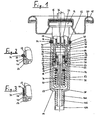
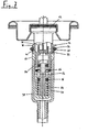
- Fig. 1 is a combined unit 10 of a spray valve 12 and a pressure regulating valve 14.
- the spray valve 12 corresponds in its constructive internal structure conventional spray valves and is therefore not closer in detail shown.
- the unit is connected to the spray valve 12 in known manner sealed by a sealing washer 16 preassembled on a valve plate 18, the following with Help of a sealing ring 20 on a can body (not shown) is fastened sealed.
- the spray valve has a spray valve housing 22, in which a stem 24 having an end 26 and a through hole is displaceable against the load of a compression spring 28.
- the Spray valve housing 22 has an intermediate wall 30 with a Through opening 32, the spray valve 12 from the pressure regulating valve 14 separates.
- a pressure relief valve 34 is provided which is substantially from one in an annular groove 36 in the outer wall the Sprühventilgepuruses 22 biased arranged annular Sealing element 38 is made, wherein in the bottom of the annular groove 36 at least one or more circumferentially arranged Passage openings 40 are provided.
- the pressure fill valve 34 has the function when filling the aerosol can in the assembled state with the help of an overpressure of for example, 12 bar, which is open with spray valve 12 of is applied externally, so that in the Sprühventilgephase 22nd this overpressure is applied, a direct fumigation of the inside of the can to allow, since the pressure regulating valve 14 at a such high pressure in the area of the spray valve housing 22 is closed is.
- the high filling pressure acts via the passage openings 40 on the annular sealing element 38 and lifts this due to the resulting pressure forces easily, so that the compressed gas past the sealing element 38 into the inside of the can can flow (see Fig. 7).
- Figs. 2 and 3 are other alternatives with an elastic, annular Sealing element shown.
- Fig. 2 is at the same annular Sealing element 38 with a circular cross-section a Annular groove 42 provided in the outer periphery of the Sprühventilgeophuses, whose flanks are formed tapered, so that a surface contact of the sealing element 38 on the flanks this groove 42 results.
- at least one passage opening 40 provided by which compressed gas during filling can flow.
- FIG. 3 an embodiment is shown, in which in the outer wall of the Sprühventilgepuruses 22 again an annular groove 44 is provided, which is similar the embodiment shown in Fig. 1 is a rectangular Has cross-section, but is made wider to a as an annular flat gasket with rectangular cross-section trained to receive 46 sealing element. Number and Execution of the passage openings 40 correspond to the in Fig. 1 embodiment shown.
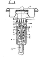
- the spray valve housing 22 has on its front side a extending from the intermediate wall 30 ring extension 48, the one part of a hollow cylinder 50 of the pressure regulating valve 14 forms, in which a control piston 52 movably guided is, which will be discussed later.
- the Ring extension 48 has at least one transverse opening at the free end 54, through which the contents of the can flow during emptying can, as will be discussed later.
- annular extension 48 On the annular extension 48 sits a cup-shaped inner housing 56. Its cylinder wall consists of a first, at a bottom 58 subsequent cylindrical wall portion 60, the inner diameter of the diameter of the control piston 52nd is adapted, a second cylindrical wall portion 62, the inner diameter of the outer diameter of the ring extension 48 is adapted and one between the two wall sections 60, 62 paragraph 64. Between paragraph 64 and the annular end surface of the annular extension 48 is an annular sealing member 66 and 67 is provided, which the Ring extension against the second cylindrical wall portion 62nd pressure-tight closes and projects into the cylinder 50, where it in cooperation with a sealing edge 68, 69 of the control piston 52 defines the sealing point of the pressure regulating valve 14.
- a sealing element 67 which in the closed state under minor elastic expansion with the annular outer surface 69 of the piston 52 sealingly cooperates while in the right half of the illustration in Fig. 1, a corner 68 of the Piston 52 with an axial end face 70 of the sealing element 66 sealingly cooperates, wherein the annular sealing element 66 in this case a little further radially inward into the Cylinder bore 50 protrudes than in the case of the annular Sealing element 67.
- the cylindrical wall portion 62 has its periphery further at least one recess 72, the in the assembled position with an associated transverse opening 54 are aligned.
- the diameter of the cylinder bore can be in the range of the second wall portion larger than in the region of be executed first wall portion, wherein the outer diameter of the piston are then also stepped accordingly.
- the sealing element is in the closed position substantially axially between the housing and jammed the shoulder of the piston, whereby u. U. mechanically less stressed.
- the control piston 52 In through the ring process 48 and the first cylindrical Wall portion 60 of the inner housing 56 formed cylinder bore 50, the control piston is movably guided.
- the control piston 52 has a lower shaft portion 74, which in the first cylindrical wall portion 60 is guided, and a upper shaft portion 76, which is guided in the annular extension 48 is.
- the two shaft portions 74, 76 are in the range the sealing point by an annular groove 78 in the control piston 52nd separated, with at least one transverse opening 80 and a central bore 82 in the upper shaft portion 76, the annular groove 78 is in communication with a pressure control chamber 84, the again via the passage opening 32 in the intermediate wall 30th is connected to the interior of the Sprühventilgephinuses 22.
- a first seal 86 in the form of an O-ring is seated in a corresponding annular groove 88 in the lower shaft portion 74th and seals it against the first cylindrical wall portion 60 of the inner housing 56 from.
- a piston extension 92 the connects the lower shaft portion 74, limits the stroke of the control piston 52, in which it rests against the bottom 58 of the inner housing 56 applies. In this way it is prevented that the annular sealing element 66 through the corner 68 of the upper Shank portion 56 is sheared off, for example, when a compressed gas filling in the pressure regulating chamber 84 a considerable Overpressure prevails, for example 12 bar.
- a second seal 94 in the form of an O-ring sits in one Ring groove 96 in the upper shaft portion 56 of the piston and seals this against the inner wall of the ring extension 48.
- Both annular grooves 88, 96 in the shaft sections 74, 76 can wider than the sealing rings 86, 94 received therein be, so that they are no in the movement of the piston Sliding movement on the inner surfaces of the cylinder bore 50, but perform a rolling motion. This is considerably less friction and improves the control accuracy of the pressure regulating valve 14th
- a cup-shaped Outer housing 98 mounted, which the inner housing 56th in the region of the cylindrical wall portion 60 and the bottom 58 surrounds with clearance, with the outer case in the bottom a nozzle 100 having a through hole 102, on which a riser 104 is placed.
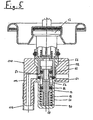
- FIG. 5 shows a further embodiment of a unit 110 shown from a spray valve 12 and a pressure regulating valve 14, wherein compared to the previously described embodiment identical components with the same reference numerals are provided.
- a cup-shaped outer casing 98 a ring attachment 112 with an integrally formed Stub 114 mounted on the inner housing 56, on which a riser 116 is attached.
- Such a solution can u. U. still claim less volume than that in Fig. 1st and 4 shown solution.
- FIG. 6 is an arrangement of a pressure regulating valve 200th shown with the aid of which a spray valve 202 for a propellant-free Aerosol spray can retrofitted with overpressure filling can be.
- the spray valve 202 sits in a known Way in a valve plate 204, wherein a housing 206 of the Spray valve 202 with a nozzle 208 for placing a Connecting tube or hose 210 is formed.
- the pressure regulating valve 200 has an upper housing part 212, which is connected to a nozzle 214 for connecting to the Connecting pipe 210 is provided, whose central through hole 216 is connected to the pressure control chamber 84.
- Upper housing part 212 is also the pressure filling valve 34th formed, with only the passage openings 40 accordingly extended to the central through-hole 216 of the housing part 212 are executed.
- the housing part instead of a neck 214, the housing part also with a sleeve-like male part Be provided directly to the nozzle 208 of the Spray valve 202 can be placed. Otherwise corresponds the pressure fill valve 200 shown in FIGS. 1 and 4 Embodiment and also works in the corresponding Wise.
- Fig. 6 offers the advantage that the previously used in propellant-filled aerosol cans Spray valves continue to be used with their valve plates can, where appropriate, only an adjustment to the higher Pressure level is required. This allows existing production facilities used cost-effectively without conversion and it will be in a simple assembly process the pressure regulating valve 200 simply upstream of the spray valve 202.
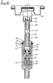
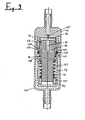
- Fig. 8 is another embodiment of a pressure regulating valve 300, which in its function substantially corresponds to the pressure relief valve 10 shown in FIG. 6, however, in which a piston 352 compared to the previously described embodiment upside down, d. H. With below, the inlet port 302 facing pressure control chamber 384th is trained.
- the passage opening 304 is above a Axial bore 306 in a housing insert 308 with a transverse opening 354 in conjunction, through which the can contents at from the sealing element 366 released sealing point via a Transverse opening 380 and a central bore 382 in the pressure control chamber 384 can flow.
- the pressure control chamber 384 is again via a throttle bore 385, for another Can provide pressure reduction, and one laterally between the Housing insert 308 and the valve housing 398 extending Connecting passage 399 with the outlet side 316 in conjunction, the to the downstream spray valve (not shown in Fig. 8) leads.
- a seal 386 pressure tight sealed chamber 389 seated compression spring 390 in turn displaces the control piston 352 at a control pressure undershot pressure in the control chamber 384 in the in Fig. 8 illustrated open position.
- a possibility for overpressure fumigation similar to those described above Embodiments, is conceivable and by an accordingly adapted housing form easily realized.
- Fig. 9 is a longitudinal section of another pressure regulating valve 400 shown in its construction of the in Figs. 1 and 7 shown embodiment is very similar, which is why functionally equivalent Components have been given the same reference numerals are. Again, a positive pressure gassing in the upper area be provided of the valve housing.
- a first difference of the pressure regulating valve of FIG. 9 is that instead of an annular disc-shaped sealing element an O-ring 466 is used as a sealing element.
- This O-ring 466 is in turn between the cup-shaped Inner housing 56 and an upper housing part 412 (similar to the Embodiment of FIG. 6) clamped, wherein the inner housing 56 and the upper housing part 412 each have an annular projection 401, 403, which are for a linear Make sealing contact with the sealing element 466, which is under many conditions of use as cheaper compared to one has proved flat system.
- Such a ring projection is also when using a ring-shaped sealing element advantageous.
- an O-ring-shaped sealing element 466 the deformations in the axial direction lower and it is a more accurate one with regard to the position of the piston Sealing possible.
- the upper housing part 412 in turn has one or a plurality of radial passage openings 454, which when open Sealing point according to FIG. 9 an outflow of the contents of the can through the openings 80, 82 in the pressure control chamber 84 and continue through a throttle bore 485, which is another Pressure reduction when flowing ensures in the through hole 216 to the spray valve (not shown).
- the piston 452 in the in Fig. 10 in which the sealing point passes through Cooperation of the sealing element 466 with a sealing flank 468 of the piston sealingly cooperates, so that the can contents no longer through the holes 80, 82 in the pressure control chamber 84 can flow.
- the sealing element 466 In the embodiment shown in Fig. 10 is otherwise radially outside of the sealing element 466 also in the region of the radial transverse openings 454 a Wall 455 provided which the sealing element 466 in this Area radially stabilized.
- a spacer sleeve 491 provided with the help of which the preload of the return spring 90 is adjustable, d. H. depending on the height of the spacer sleeve 491 can also be the control characteristics of the pressure regulating valve 400.
- FIGS. 8, 9 and 10 300, 400 a Pressure regulating valve are similar for an arrangement Fig. 6, wherein the pressure regulating valve 300 or 400 with Help a hose or nozzle upstream of a spray valve becomes.
- FIGS. 8, 9 and 10 common Special feature continues to be that for sealing of the piston 452 relative to the housing parts 56, 412 used Sealing rings 86, 94 are disposed in grooves 488 and 496, respectively, which are wider than the sealing rings 86, 94 so that they themselves can roll on an axial movement of the piston 452 and not just to be moved in a purely sliding manner. This can be done reduce the friction losses in the piston movement, which in turn the control accuracy benefits. This feature is of course, in the other described embodiments can be used advantageously.
Abstract
Description
Die vorliegende Erfindung befaßt sich mit einem Druckregulierventil zum Einsatz in einer Aerosolsprühdose mit einem Sprühventil, wobei das Druckregulierventil ein in dem mit komprimiertem Gas befüllten Doseninneren herrschendes Druckniveau auf ein Regeldruckniveau absenkt, auf welchem das Sprühventil arbeitet, das Druckregulierventil einen in einem Gehäuse geführten Regelkolben aufweist, der zwischen einem in einer Druckregelkammer auf die Kolbenfläche wirkenden Druck und einer Rückstellkraft im Gleichgewicht gehalten ist, und zwischen dem Regelkolben und dem Gehäuse eine Dichtstelle vorgesehen ist, die bei einem Druck in der Druckregelkammer oberhalb des Regeldruckniveaus verschlossen ist.The present invention is concerned with a pressure regulating valve for use in an aerosol spray can with a Spray valve, wherein the pressure regulating a in the with compressed gas filled can interior pressure level prevailing lowers to a standard pressure level on which the Spray valve works, the pressure regulating valve in one Housing guided control piston having between a in a pressure-regulating chamber acting on the piston surface pressure and a restoring force is maintained in equilibrium, and between the control piston and the housing a sealing point is provided, which at a pressure in the pressure control chamber is closed above the control pressure levels.
Derartige Druckregulierventile werden bei Aerosolsprühdosen benötigt, die ohne Treibgas arbeiten, d. h. chemische Aerosol-Treibmittel, wobei es der Verzicht auf solche Treibgase notwendig macht, die Aerosoldose auf einen deutlich höheren Druck zu befüllen, beispielsweise 10 bar. Da die Sprühventile auf einem bestimmten niedrigeren Druckniveau arbeiten, wie auch bei bisher verwendeten Aerosolsprühdosen mit Treibgasbefüllung, und eine möglichst vollständige Restentleerung der Dose gegeben sein soll, ist es notwendig ein Druckregulierventil einzusetzen, das dem Sprühventil vorgeschaltet wird und den Doseninnendruck auf den für das Sprühventil geeigneten Druck von z. B. 3 bar absenkt. Druckregulierventile der eingangs beschriebenen Art sind beispielsweise in der WO 01/09009 A1, der EP 0 931 734 A1 und in der WO 01/96208 A1 beschrieben. Alle in diesen Druckschriften beschriebenen Druckreduzierventile haben den Nachteil, daß der anfänglich sehr hohe Doseninnendruck auf eine Axialfläche des Kolbenelements wirkt, wobei selbst in den Fällen, in denen nur das vergleichsweise kleine Schaftende des Kolbens mit dem hohen Druck beaufschlagt ist, eine nicht unbeträchtliche Axialkraft auf das Kolbenelement entsteht. Würde der Doseninnendruck konstant bleiben, könnte man diese Störkraft leicht korrigieren. Da jedoch der Doseninnendruck bei zunehmender Entleerung des Inhaltes kontinuierlich abnimmt, verändert sich auch die Größe der Störkraft, so daß die Störgröße nicht mehr ohne weiteres kompensiert werden kann. Letztlich führt dies dazu, daß der Regeldruck des Druckregulierventils sich abhängig vom noch bestehenden Fülldruck der Aerosolsprühdose verändert, was unerwünscht ist, da hierdurch das Sprühventil nicht mehr optimal arbeiten kann. Einen Ausgleich kann man zwar dadurch schaffen, daß man die Kolbenfläche im Bereich der Druckregelkammer möglichst groß wählt, so daß die axiale Stirnfläche beispielsweise des Kolbenschaftes als Störgröße weniger ins Gewicht fällt, dies bedingt jedoch eine erhebliche Zunahme des Bauvolumens des Druckreduzierventils, was auf Kosten des maximal möglichen Doseninhaltes geht. Je kleiner die Kolbenfläche in der Druckregelkammer jedoch gewählt wird, desto größer ist die Abweichung des Regeldruckes zwischen dem Anfangszustand und dem nahezu völlig entleerten Zustand.Such pressure regulating valves are aerosol spray cans needed, which work without propellant, d. H. chemical aerosol propellants, where it is the abandonment of such propellant gases necessary, the aerosol can to a much higher To fill pressure, for example 10 bar. Because the spray valves working at a certain lower pressure level, like also in previously used aerosol spray cans with LPG filling, and as complete as possible emptying of the If it is necessary, it is necessary a pressure regulating valve insert, which is connected upstream of the spray valve and the internal pressure of the can suitable for the spray valve Pressure of z. B. 3 bar lowers. Pressure regulating valves of The type described above are, for example, in the WO 01/09009 A1, EP 0 931 734 A1 and in WO 01/96208 A1 described. All described in these publications Pressure reducing valves have the disadvantage that the initial very high dose pressure on an axial surface of the piston element works, even in cases where only that comparatively small shaft end of the piston with the high Pressure is applied, a not inconsiderable axial force arises on the piston element. Would the dose internal pressure remain constant, one could correct this disturbance easily. However, since the internal dose pressure with increasing emptying the content continuously decreases, so does the Size of the disturbing force, so that the disturbance no longer without more can be compensated. Ultimately, this leads to that the control pressure of the pressure regulating valve depends on still existing filling pressure of the aerosol spray can changed, which is undesirable because it stops the spray valve can work optimally. A balance can be made by it create that the piston surface in the region of the pressure control chamber chooses as large as possible, so that the axial end face For example, the piston skirt as a disturbance less ins Weight drops, but this requires a significant increase the construction volume of the pressure reducing valve, which at the expense of maximum possible contents of cans. The smaller the piston area However, in the pressure control chamber is chosen, the greater is the deviation of the control pressure between the initial state and the almost completely empty state.
Die Aufgabe der vorliegenden Erfindung besteht darin, ein Druckregulierventil der eingangs beschriebenen Art dahingehend zu verbessern, daß bei möglichst kleinem Bauvolumen eine höhere Regelgenauigkeit bei unterschiedlichem Doseninnendruck erreicht wird.The object of the present invention is a Pressure regulating valve of the type described above to the effect to improve that with the smallest possible volume of construction higher control accuracy with different internal pressure of the can is reached.
Erfindungsgemäß wird die Aufgabe dadurch gelöst, daß bei einem Druckregulierventil der eingangs beschriebenen Art eine Abdichtung vorgesehen ist, die ein freies, von der Druckregelkammer abgewandtes Ende des Kolbens gegen den Doseninnendruck und gegen den Regeldruck abdichtet, so daß die auf Axialflächen am freien Ende des Kolbens wirkenden Drücke unabhängig vom Druckniveau des Doseninhaltes sind.According to the invention the object is achieved in that at a Pressure regulating valve of the type described above a Sealing is provided, which is a free, from the pressure control chamber opposite end of the piston against the can internal pressure and seals against the control pressure, so that on Axial surfaces at the free end of the piston acting pressures independently from the pressure level of the can contents.
Durch die Abschirmung auch des bislang dem Doseninnendruck ausgesetzten freien Endes des Regelkolbens wird die sich in Abhängigkeit vom Befüllungsgrad und damit dem Doseninnendruck verändernde Störkraft eliminiert, so daß der Regeldruck des Druckregulierventils nicht mehr vom augenblicklich bestehenden Doseninnendruck abhängt. Darüber hinaus kann der Kolbendurchmesser klein gehalten werden, da aufgrund des abgeschirmten freien Endes die Genauigkeit des Ventils nicht mehr von der Größe der Kolbenfläche in der Druckregelkammer abhängt, sondern mit einer kleineren Fläche und einer entsprechend darauf abgestimmten Rückstellkraft gearbeitet werden kann, die z. B. durch eine Feder oder ein Gasdruckpolster erzeugt wird. Hierdurch verringert sich der Bauraum des Druckregulierventils, d. h. es steht mehr Doseninhalt zur Befüllung zur Verfügung.Due to the shielding of so far the can internal pressure exposed free end of the control piston is in Dependence on the degree of filling and thus the internal pressure of the can eliminates changing disturbance force, so that the control pressure of the Pressure regulating valve no longer of the currently existing Can internal pressure depends. In addition, the piston diameter kept small because of the shielded free end, the accuracy of the valve is no longer depends on the size of the piston area in the pressure regulating chamber, but with a smaller area and one accordingly matched restoring force to be worked can, for. B. generated by a spring or a gas pressure cushion becomes. This reduces the space of the pressure regulating valve, d. H. There is more can contents to fill to disposal.
In einer bevorzugten Ausführungsform der Erfindung ist vorgesehen, daß die Dichtstelle in einem mittleren Bereich des Regelkolbens vorgesehen ist, der an dieser Stelle vorzugsweise eine Ringnut aufweist. Auf diese Weise läßt sich eine einfache Abschirmung des freien Endes erreichen, beispielsweise mit Hilfe eines Dichtringes als erster Dichtung, der den Spalt zwischen dem Kolben und dem ihn umgebenden Gehäuse verschließt. Andererseits kann bei dieser Anordnung die Dichtstelle einfach mit Hilfe eines beispielsweise radial in die Ringnut ragenden O-ring- oder ringscheibenförmigen Dichtelements ausgebildet werden. Die Verbindung zwischen der Dichtstelle und der Druckregelkammer erfolgt vorzugsweise über Öffnungen in dem Kolben, beispielsweise durch eine Querbohrung von der Dichtstelle ausgehend und eine Axialbohrung, die die Querbohrung mit der Druckregelkammer verbindet.In a preferred embodiment of the invention is provided that the sealing point in a central region of the control piston is provided, preferably at this point has an annular groove. In this way, can be a simple To achieve shielding of the free end, for example with the help of a sealing ring as the first seal, the Gap between the piston and the surrounding housing closes. On the other hand, in this arrangement, the sealing point Simply with the help of a for example radially in the Ring groove projecting O-ring or annular disc-shaped sealing element be formed. The connection between the sealing point and the pressure regulating chamber is preferably via Openings in the piston, for example by a transverse bore starting from the sealing point and an axial bore, the the transverse bore connects to the pressure control chamber.
In bevorzugter Weiterbildung der Erfindung ist vorgesehen, daß der Kolbenschaft beidseitig der Dichtstelle gegen das Gehäuse abgedichtet ist, wobei auf einer Seite eine erste Dichtung als Teil der Abdichtung des freien Endes vorgesehen ist. Die Anordnung der Dichtstelle im mittleren Bereich des Regelkolbens bietet den Vorteil, daß zu beiden. Seiten eine einfache Abdichtung des Spaltes zwischen Kolben und Gehäuse gegen den Doseninnendruck möglich ist. Eine Dichtung sorgt dafür, daß die Druckregelkammer von dem Doseninnendruck abgedichtet ist, während die erste Dichtung für die Abdichtung einer geschlossenen Kammer sorgt, in welcher neben dem freien Ende des Kolbens vorzugsweise auch die Rückstellfeder angeordnet ist, die beispielsweise als Schraubenfeder oder als Druckgasfeder ausgebildet sein kann. Mit Hilfe von in der Länge unterschiedlichen Distanzhülsen oder -scheiben kann die Vorspannkraft der Feder bei im übrigen unverändertem Druckregulierventil leicht eingestellt werden. In a preferred embodiment of the invention is provided that the piston skirt on both sides of the sealing point against the housing is sealed, with a first seal on one side is provided as part of the seal of the free end. The arrangement of the sealing point in the middle region of the control piston offers the advantage that to both. Pages a simple one Sealing of the gap between the piston and the housing against the inside of the can is possible. A seal ensures that the pressure-regulating chamber is sealed by the internal pressure of the can is while the first seal for sealing a closed Chamber ensures, in which next to the free end the piston preferably also arranged the return spring is, for example, as a coil spring or as a compressed gas spring can be trained. With the help of different in length Spacers or discs can the biasing force the spring at the otherwise unchanged pressure regulating valve be easily adjusted.
Vorzugsweise ist weiterhin vorgesehen, daß der Kolbendurchmesser von der Dichtstelle aus gesehen in beiden Axialrichtungen unterschiedlich ausgeführt ist. Hierdurch wird die Möglichkeit geschaffen, in weiterer bevorzugter Ausführungsform der Erfindung mit dem zuvor bereits erwähnten O-ring- oder ringscheibenförmigen Dichtelement die Dichtstelle auszubilden, wobei das Dichtelement an dem Kolben oder dem Gehäuse festgelegt ist und mit einem Absatz, der durch den Durchmesserunterschied gebildet sein kann, am Gehäuse bzw. dem Kolben abdichtend zusammenwirkt, wenn der Druck in der Druckregelkammer das Regeldruckniveau übersteigt. Kolben- und Gehäusedurchmesser sind selbstverständlich in den jeweiligen Abschnitten zueinander passend ausgeführt.Preferably, it is further provided that the piston diameter seen from the sealing point in both axial directions is executed differently. This will be the Possibility created, in another preferred embodiment invention with the above-mentioned O-ring or annular disc-shaped sealing element to form the sealing point, wherein the sealing element on the piston or the housing is fixed and with a paragraph, by the difference in diameter may be formed on the housing or the piston sealingly cooperates when the pressure in the pressure regulating chamber exceeds the standard pressure level. Piston and housing diameter are of course in the respective sections designed to match each other.
In einer noch weiteren bevorzugten Ausführungsform ist vorgesehen, daß das zylindrische Gehäuse zwei Teile mit gleichen oder unterschiedlichen, den Kolbendurchmessern angepaßten Innendurchmessern aufweist, wobei zwischen den beiden Teilen das Dichtelement, vorzugsweise mit einem Ringgrat oder - vorsprung zum Erreichen einer linienförmigen Dichtstelle mit wenigstens einem Teil, festgelegt ist. Bei dieser Variante wird das Dichtelement zwischen den beiden Gehäuseteilen sicher und druckdicht verklemmt.In a still further preferred embodiment it is provided that the cylindrical housing with two parts or different inner diameters adapted to the piston diameters having, between the two parts the sealing element, preferably with a ring ridge or - protrusion to reach a linear sealing point with at least one part. In this variant the sealing element between the two housing parts is safe and clamped pressure-tight.
Die Abdichtung des beweglichen Kolbens zu dem Gehäuse erfolgt vorzugsweise mit Hilfe von O-Ringen, die in Nuten im Gehäuse oder dem Kolben angeordnet sind. In weiterer bevorzugter Ausgestaltung ist dabei vorgesehen, daß die Nuten breiter als der jeweilige O-Ring ausgebildet sind, wobei die Breite der Nuten in besonders bevorzugter Ausbildung derart gewählt ist, daß der O-Ring im Verstellbereich des Kolbens im wesentlichen reibungsfrei auf dem Nutgrund und der gegenüberliegenden Dichtfläche der Kolbenaußenseite bzw. der Gehäuseinnenseite abrollt. Gegenüber einer gleitenden Ringdichtung bietet eine derartige Ausbildung den Vorteil, daß die Reibungskräfte beim Verstellen des Kolbens wesentlich geringer sind, so daß die zur Druckregelung notwendige Beweglichkeit des Kolbens mit geringeren Reibkräften erreicht wird, wodurch wiederum das Regelergebnis positiv beeinflußt wird.The sealing of the movable piston to the housing takes place preferably by means of O-rings, which are in grooves in the housing or the piston are arranged. In a further preferred embodiment is provided that the grooves wider than the respective O-ring are formed, wherein the width of the Grooves is selected in a particularly preferred embodiment such that the O-ring in the adjustment of the piston substantially frictionless on the groove bottom and the opposite Sealing surface of the piston outside or the inside of the housing unrolls. Compared to a sliding ring seal offers one Such training has the advantage that the frictional forces during Adjusting the piston are much lower, so that the necessary for pressure control mobility of the piston with lower friction forces is achieved, which in turn the Result is positively influenced.
In einer weiteren bevorzugten Ausführungsform der Erfindung ist das Gehäuseteil zur Aufnahme des freien Endes des Kolbens von einem becherförmigen Gehäuseteil umgeben, das einen Teil der Verbindung des Doseninneren mit der Dichtstelle bildet. Diese Ausführungsform läßt sich aufgrund der im wesentlichen rotationssymmetrischen Gehäuseteile besonders kostengünstig fertigen, während es grundsätzlich auch vorstellbar ist, die Dichtstelle mit einem am Gehäuse angeformten oder angebrachten Stutzen mit dem Doseninneren zu verbinden.In a further preferred embodiment of the invention is the housing part for receiving the free end of the piston surrounded by a cup-shaped housing part, which is a part forms the connection of the inside of the can with the sealing point. This embodiment can be due to the substantially rotationally symmetrical housing parts particularly inexpensive While it is also conceivable in principle, the Seal with a molded or attached to the housing Connecting the nozzle with the inside of the can.
Vorteilhaft kann auch das Vorsehen einer Drosselstelle zwischen der Druckregelkammer und dem Sprühventil sein. Hierdurch kann der Regeldruck zwischen der Kammer und dem Sprühventil weiter reduziert werden.Advantageously, the provision of a throttle point between the pressure control chamber and the spray valve. hereby can regulate pressure between the chamber and the spray valve be further reduced.
Das zuvor beschriebene Druckregulierventil kann als separate Einheit ausgebildet sein und beispielsweise über einen Stutzen, eine Steckhülse oder dgl. verfügen, mit Hilfe dessen/derer es unmittelbar oder über ein Rohr- oder Schlauchstück mit einem Stutzen eines Sprühventils verbindbar ist. Eine derartige Ausbildung erlaubt es, eine herkömmliche Aerosolsprühdose durch einfaches Vorschalten des Druckregulierventils am zur Anbringung üblicherweise eines Steigrohres ohnehin vorgesehenen Stutzen des Sprühventils umzurüsten, wobei ggf. lediglich der Dosenkörper den erhöhten Druckverhältnissen anzupassen ist. Gegenstand der vorliegenden Erfindung sind jedoch in gleicher Weise auch eine Aerosolsprühdose mit einem Sprühventil und einem diesem vorgeschalteten Druckminderventil in einer der zuvor beschriebenen Ausführungen sowie eine Ventileinheit zum Einbau in eine Aerosolsprühdose, die aus einem Sprühventil und einem Druckminderventil der zuvor beschriebenen Art als montagefertige Einheit ausgebildet ist.The pressure regulating valve described above can be used as a separate Unit be formed and for example via a nozzle, a socket or the like. Have, with the help of which / it directly or via a pipe or hose piece with a nozzle of a spray valve is connectable. Such Training allows a conventional aerosol spray can simply by connecting the pressure regulating valve on for mounting usually a riser provided anyway Convert the nozzle of the spray valve, where necessary only to adapt the can body to the increased pressure conditions is. However, the subject of the present invention is in the same way also an aerosol spray can with a spray valve and a pressure reducing valve upstream of this one of the embodiments described above and a valve unit for installation in an aerosol spray can, which consists of a Spray valve and a pressure reducing valve of the previously described Art is designed as a ready to install unit.
Eine weitere Neuerung, die auch bei anderen Druckregulierventilen zum Einsatz kommen kann, sieht vor, daß am Ausgangsende des Druckregulierventils zum Sprühventil ein Überdruckfüllventil vorgesehen ist, das oberhalb eines vorbestimmten Grenzdruckes in dem Raum zwischen dem Sprühventil und dem Druckminderventil einen Querschnitt zum Befüllen der Aerosoldose freigibt. Da zumindest ein erheblicher Teil der Befüllung der Dose durch die Ventile vorgenommen werden soll, um den Füllvorgang zu verkürzen, ist der Einsatz eines solchen Überdruckfüllventils sinnvoll, da die meisten Druckregulierventile bei einer Druckbeaufschlagung von außen keinen Querschnitt freigeben oder einzelne Dichtelemente überbeansprucht werden.Another innovation, which also with other pressure regulating valves can be used, provides that at the output end of the pressure regulating valve to the spray valve a pressure filling valve is provided, which is above a predetermined Limit pressure in the space between the spray valve and the Pressure reducing valve a cross section for filling the aerosol can releases. Because at least a significant part of the filling the can through the valves should be made to shortening the filling process is the use of such Pressure relief valve useful, since most pressure regulating valves at a pressurization from the outside no cross-section release or overloaded individual sealing elements become.
Nachfolgend wird anhand der beigefügten Zeichnungen näher auf Ausführungsbeispiele der Erfindung eingegangen. Es zeigen:
- Fig. 1
- einen Längsschnitt einer kombinierten Einheit aus einem Sprühventil und einem Druckregulierventil für eine Aerosolsprühdose;
- Fig. 2
- eine Einzelheit einer alternativen Ausführungsform eines Ventils der Einheit nach Fig. 1 zur Überdruckbefüllung;
- Fig. 3
- eine Einzelheit einer weiteren Ausführungsform des Ventils zur Überdruckbefüllung;
- Fig. 4
- einen Längsschnitt der Einheit nach Fig. 1 mit geöffnetem Ventilquerschnitt des Druckregulierventils;
- Fig. 5
- einen Längsschnitt einer weiteren Ausführungsform einer Einheit aus Sprühventil und Druckregulierventil;
- Fig. 6
- einen Längsschnitt eines Ventilbereichs einer Aerosolsprühdose mit getrennt ausgeführtem Sprühventil und Druckregulierventil;
- Fig. 7
- einen Längsschnitt der Einheit nach Fig. 1 mit geöffnetem Überdruckfüllventil.
- Fig. 8
- einen Längsschnitt einer weiteren Ausführungsform eines Druckregulierventils;
- Fig. 9
- einen Längsschnitt einer noch weiteren Ausführungsform eines Druckregulierventils in der geöffneten Stellung;
- Fig.10
- einen Längsschnitt eines Druckregulierventils im geschlossenen Zustand, das i. w. dem Druckregulierventil aus Fig. 9 entspricht.
- Fig. 1
- a longitudinal section of a combined unit of a spray valve and a pressure regulating valve for an aerosol spray can;
- Fig. 2
- a detail of an alternative embodiment of a valve of the unit of Figure 1 for overpressure filling.
- Fig. 3
- a detail of another embodiment of the valve for overpressure filling;
- Fig. 4
- a longitudinal section of the unit of Figure 1 with the valve cross-section of the pressure regulating valve.
- Fig. 5
- a longitudinal section of another embodiment of a unit of spray valve and pressure regulating valve;
- Fig. 6
- a longitudinal section of a valve portion of an aerosol spray can with separately executed spray valve and pressure regulating valve;
- Fig. 7
- a longitudinal section of the unit of FIG. 1 with opened pressure relief valve.
- Fig. 8
- a longitudinal section of another embodiment of a pressure regulating valve;
- Fig. 9
- a longitudinal section of yet another embodiment of a pressure regulating valve in the open position;
- Figure 10
- a longitudinal section of a pressure regulating valve in the closed state, which corresponds iw the pressure regulating valve of FIG. 9.
In Fig. 1 ist eine kombinierte Einheit 10 aus einem Sprühventil
12 und einem Druckregulierventil 14 gezeigt. Das Sprühventil
12 entspricht in seinem konstruktiven inneren Aufbau
herkömmlichen Sprühventilen und ist daher nicht näher im Detail
gezeigt. Die Einheit ist mit dem Sprühventil 12 in an
sich bekannter Weise mittels einer Dichtscheibe 16 abgedichtet
an einem Ventilteller 18 vormontiert, der nachfolgend mit
Hilfe eines Dichtrings 20 an einem Dosenkörper (nicht gezeigt)
abgedichtet befestigt wird.In Fig. 1 is a combined
Das Sprühventil besitzt ein Sprühventilgehäuse 22, in welchem
ein Stem 24 mit ein einem Ende 26 und einer Durchgangsöffnung
gegen die Last einer Druckfeder 28 verschieblich ist. Das
Sprühventilgehäuse 22 besitzt eine Zwischenwand 30 mit einer
Durchgangsöffnung 32, die das Sprühventil 12 von dem Druckregulierventil
14 trennt. In der Wandung des Sprühventilgehäuses
22 ist ein Überdruckfüllventil 34 vorgesehen, das im wesentlichen
aus einem in einer Ringnut 36 in der Außenwandung
des Sprühventilgehäuses 22 vorgespannt angeordneten ringförmigen
Dichtelement 38 besteht, wobei im Boden der Ringnut 36
wenigstens eine oder mehrere über den Umfang angeordnete
Durchtrittsöffnungen 40 vorgesehen sind. Das Überdruckfüllventil
34 hat die Funktion, bei einer Befüllung der Aerosoldose
im montierten Zustand mit Hilfe eines Überdruckes von
beispielsweise 12 bar, der bei geöffnetem Sprühventil 12 von
außen aufgebracht wird, so daß in dem Sprühventilgehäuse 22
dieser Überdruck anliegt, eine direkte Begasung des Doseninneren
zu ermöglichen, da das Druckregulierventil 14 bei einem
derart hohen Druck im Bereich des Sprühventilgehäuses 22 geschlossen
ist. Der hohe Fülldruck wirkt über die Durchtrittsöffnungen
40 auf das ringförmige Dichtelement 38 und hebt
dieses infolge der entstehenden Druckkräfte leicht an, so daß
das komprimierte Gas an dem Dichtelement 38 vorbei in das Doseninnere
strömen kann (s. Fig 7). Nach Beenden des Füllvorganges
wird die Druckbeaufschlagung beendet und das ringförmige
Dichtelement 38 legt sich infolge seiner Eigenelastizität
und insbesondere unter dem nun auf ihn wirkenden Doseninnendruck
fest an den Durchtrittsöffnungen 40 an, so daß diese
dauerhaft verschlossen sind und der Druck in dem Sprühventilgehäuse
22 auf ein gewünschtes Druckniveau abfallen kann.The spray valve has a
Als Überdruckfüllventil kann in diesem Bereich grundsätzlich
jegliche Art von Ventil Verwendung finden, die gezeigte Ausführungsform
mit einem ringförmigen Dichtelement läßt sich
jedoch besonders einfach realisieren. In Fig. 2 und 3 sind
weitere Alternativen mit einem elastischen, ringförmigen
Dichtelement dargestellt. In Fig. 2 ist bei gleichem ringförmigem
Dichtelement 38 mit kreisförmigem Querschnitt eine
Ringnut 42 im Außenumfang des Sprühventilgehäuses vorgesehen,
deren Flanken schräg zulaufend ausgebildet sind, so daß sich
eine flächigere Anlage des Dichtelements 38 an den Flanken
dieser Nut 42 ergibt. Wiederum ist wenigstens eine Durchtrittsöffnung
40 vorgesehen, durch welche Druckgas beim Befüllen
strömen kann. In Fig. 3 ist eine Ausführungsform gezeigt,
bei welcher in der Außenwandung des Sprühventilgehäuses
22 wiederum eine Ringnut 44 vorgesehen ist, die ähnlich
der in Fig. 1 gezeigten Ausführungsform einen rechteckigen
Querschnitt besitzt, jedoch breiter ausgeführt ist, um ein
als ringförmige Flachdichtung mit rechteckigem Querschnitt
ausgebildetes Dichtelement 46 aufnehmen zu können. Zahl und
Ausführung der Durchtrittsöffnungen 40 entsprechen der in
Fig. 1 gezeigten Ausführungsform.As overpressure filling valve can in this area in principle
find any type of valve use, the embodiment shown
can be with an annular sealing element
but especially easy to realize. In Figs. 2 and 3 are
other alternatives with an elastic, annular
Sealing element shown. In Fig. 2 is at the same
Das Sprühventilgehäuse 22 besitzt an seiner Stirnseite einen
sich von der Zwischenwand 30 erstreckenden Ringfortsatz 48,
der einen Teil eines Hohlzylinders 50 des Druckregulierventils
14 bildet, in welchem ein Regelkolben 52 beweglich geführt
ist, auf den später noch näher eingegangen wird. Der
Ringfortsatz 48 besitzt am freien Ende wenigstens eine Queröffnung
54, durch welche der Doseninhalt beim Entleeren strömen
kann, worauf später noch näher eingegangen wird.The
Auf dem Ringfortsatz 48 sitzt ein becherförmiges Innengehäuse
56. Dessen Zylinderwandung besteht aus einem ersten, sich an
einen Boden 58 anschließenden zylindrischen Wandabschnitt 60,
dessen Innendurchmesser dem Durchmesser des Regelkolbens 52
angepaßt ist, einem zweiten zylindrischen Wandabschnitt 62,
dessen Innendurchmesser dem Außendurchmesser des Ringfortsatzes
48 angepaßt ist und einem zwischen den beiden Wandabschnitten
60, 62 liegenden Absatz 64. Zwischen dem Absatz 64
und der ringförmigen Stirnfläche des Ringfortsatzes 48 ist
ein ringförmiges Dichtelement 66 bzw. 67 vorgesehen, das den
Ringfortsatz gegen den zweiten zylindrischen Wandabschnitt 62
druckdicht verschließt und in den Zylinder 50 ragt, wobei es
im Zusammenwirken mit einer Dichtflanke 68, 69 des Regelkolbens
52 die Dichtstelle des Druckregulierventils 14 definiert.
In der linken Hälfte der Darstellung ist ein Dichtelement
67 dargestellt, das im Schließzustand unter geringfügiger
elastischer Aufweitung mit der ringförmigen Außenfläche
69 des Kolbens 52 abdichtend zusammenwirkt, während in der
rechten Hälfte der Darstellung in Fig. 1 eine Ecke 68 des
Kolbens 52 mit einer axialen Stirnfläche 70 des Dichtelements
66 abdichtend zusammenwirkt, wobei das ringförmige Dichtelement
66 in diesem Fall etwas weiter radial nach innen in die
Zylinderbohrung 50 vorsteht als im Falle des ringförmigen
Dichtelements 67. Der zylindrische Wandabschnitt 62 weist auf
seinem Umfang ferner wenigstens eine Aussparung 72 auf, die
in der montierten Stellung mit einer zugehörigen Queröffnung
54 fluchten. Der Durchmesser der Zylinderbohrung kann im Bereich
des zweiten Wandabschnittes größer als im Bereich des
ersten Wandabschnittes ausgeführt sein, wobei die Außendurchmesser
des Kolbens dann ebenfalls entsprechend gestuft sind.
Bei einer solchen Ausführungsform wird das Dichtelement in
der Schließstellung im wesentlichen axial zwischen dem Gehäuse
und dem Absatz des Kolbens verklemmt, wodurch es u. U. mechanisch
weniger stark beansprucht ist. On the annular extension 48 sits a cup-shaped
In der durch den Ringfortsatz 48 und den ersten zylindrischen
Wandabschnitt 60 des Innengehäuses 56 gebildeten Zylinderbohrung
50 ist der Regelkolben beweglich geführt. Der Regelkolben
52 weist einen unteren Schaftabschnitt 74, der in dem ersten
zylindrischen Wandabschnitt 60 geführt ist, und einen
oberen Schaftabschnitt 76 auf, der in dem Ringfortsatz 48 geführt
ist. Die beiden Schaftabschnitte 74, 76 sind im Bereich
der Dichtstelle durch eine Ringnut 78 in dem Regelkolben 52
getrennt, wobei über wenigstens eine Queröffnung 80 und eine
mittige Bohrung 82 im oberen Schaftabschnitt 76 die Ringnut
78 mit einer Druckregelkammer 84 in Verbindung steht, die
wiederum über die Durchgangsöffnung 32 in der Zwischenwand 30
mit dem Inneren des Sprühventilgehäuses 22 verbunden ist.In through the ring process 48 and the first
Eine erste Dichtung 86 in der Form eines O-Rings sitzt in einer
entsprechenden Ringnut 88 im unteren Schaftabschnitt 74
und dichtet diesen gegen den ersten zylindrischen Wandabschnitt
60 des Innengehäuses 56 ab. Hierdurch entsteht zwischen
dem unteren Schaftabschnitt 74, dem ersten zylindrischen
Wandabschnitt und dem Boden 58 des Innengehäuses 56 eine
druckdicht abgeschlossene Kammer 89, in welcher eine Rückstellfeder
90 angeordnet ist, die eine definierte Rückstellkraft
auf den Kolben 52 ausübt. Ein Kolbenfortsatz 92, der an
dem unteren Schaftabschnitt 74 anschließt, begrenzt den Hubweg
des Regelkolbens 52, in dem er sich am Boden 58 des Innengehäuses
56 anlegt. Auf diese Weise wird verhindert, daß
das ringförmige Dichtelement 66 durch die Ecke 68 des oberen
Schaftabschnitts 56 abgeschert wird, wenn beispielsweise bei
einer Druckgasbefüllung in der Druckregelkammer 84 ein erheblicher
Überdruck herrscht, beispielsweise 12 bar.A
Eine zweite Dichtung 94 in Form eines O-Rings sitzt in einer
Ringnut 96 im oberen Schaftabschnitt 56 des Kolbens und dichtet
diesen gegen die Innenwandung des Ringfortsatzes 48 ab.
Beide Ringnuten 88, 96 in den Schaftabschnitten 74, 76 können
breiter als die darin aufgenommenen Dichtringe 86, 94 ausgebildet
sein, so daß diese bei der Bewegung des Kolbens keine
Gleitbewegung an den Innenflächen der Zylinderbohrung 50,
sondern eine Rollbewegung ausführen. Diese ist erheblich reibungsärmer
und verbessert die Regelgenauigkeit des Druckregulierventils
14.A
Auf der Außenwandung des Innengehäuses 56 ist ein becherförmiges
Außengehäuse 98 aufgesetzt, welches das Innengehäuse 56
im Bereich des zylindrischen Wandabschnittes 60 und des Bodens
58 mit Abstand umgibt, wobei das Außengehäuse im Boden
einen Stutzen 100 mit einer Durchgangsbohrung 102 aufweist,
auf welchen ein Steigrohr 104 aufgesetzt ist.On the outer wall of the
Bei der in Fig. 1 gezeigten Ruhestellung ist im montierten
Zustand nach einer Druckbefüllung des Aerosolbehältnisses die
Dichtstelle durch das Zusammenwirken der Außenfläche 69 bzw.
der Ecke 68 des oberen Schaftabschnittes 76 des Kolbens im
Zusammenwirken mit dem jeweils vorgesehenen ringförmigen
Dichtelement 66 oder 67 verschlossen, und auch das Sprühventil
12 ist abgedichtet. Dies bedeutet, daß im Doseninneren,
im Steigrohr 104, in der Durchgangbohrung 102, zwischen dem
Innengehäuse 56 und dem Außengehäuse 98 sowie in den Aussparungen
72 und den Queröffnungen 54 das Fülldruckniveau von
beispielsweise 10 bar herrscht. Stromabwärts der Dichtstelle
herrscht nach einmaligem Betätigen des Sprühventils 12 in der
Ringnut 78, der Queröffnung 80, der mittigen Bohrung 82, der
Druckregelkammer 84 und dem Inneren des Sprühventilgehäuses
22 der gewünschte Regeldruck von beispielsweise 3 bar, wobei
die Rückstellfeder 90 in der Kammer 89 komprimiert ist und
sich der Kolbenfortsatz 92 bei dem gezeigten Ausführungsbeispiel
am Boden 58, was nicht zwingend der Fall sein muß, angelegt
hat. Der Regeldruck wirkt in der Druckregelkammer auf
die axiale Stirnfläche des Regelkolbens 52, während sich im
mittleren Bereich die Wirkung des Druckes auf die sich gegenüberliegenden
Axialflächen der beiden Schaftabschnitte 74,
76 des Kolbens 52 aufhebt.In the rest position shown in Fig. 1 is mounted in the
Condition after a pressure filling of the aerosol container the
Sealing point by the interaction of the
Erfolgt eine Entnahme von Doseninhalt durch Betätigen des
Sprühventils 12 sinkt der Druck u. a. in der Druckregelkammer
84 ab, d. h. die auf den Kolben 52 entgegen der Rückstellfeder
90 wirkenden Axialkräfte nehmen ab. Dadurch ist die Rückstellfeder
90 ggf. im Zusammenwirken mit einem in der Kammer
89 bestehenden Überdruck in der Lage, den Kolben in Richtung
der in Fig. 4 gezeigten Endstellung zu bewegen, wobei allerdings
die in Fig. 4 gezeigte, durch einen Ringanschlag 106 am
oberen Schaftabschnitt 76 durch Anlage an der Zwischenwand 30
begrenzte Endstellung in der Regel nur bei sehr starker Entnahme
oder bereits sehr stark abgesenktem Druckniveau im Doseninneren
erreicht wird. Der Ringanschlag kann zur Vermeidung
einer großflächigen Anlage, die Einfluß auf das Regelverhalten
haben könnte, mit einer Schräge, d. h. einem linienförmigen
Kontaktbereich, oder Punkten bzw. Warzen für eine
punktuelle Anlage versehen sein. In jedem Fall wird die
Dichtfläche 68, 69 des oberen Schaftabschnitts 76 vom jeweiligen
Dichtelement 66, 67 abgehoben, so daß sich zwischen den
Queröffnungen 54 und der Ringnut 78 ein Querschnitt öffnet,
durch den der Doseninhalt zum Sprühventil gelangen kann. Nach
dem Verschließen des Sprühventils sorgt das Regeldruckniveau
u. a. in der Druckregelkammer 84 dafür, daß der Kolben 52
wieder in seine in Fig. 1 gezeigte Stellung gelangt und damit
wiederum eine Abdichtung der unter dem Regeldruckniveau stehenden
Bereiche von dem höheren Druckniveau im Doseninneren
erreicht wird. Damit wird sichergestellt, daß das Sprühventil
12 immer auf einem nahezu konstanten Druckniveau von beispielsweise
3 bar arbeiten kann, während sich das Druckniveau
im Doseninneren von anfänglich beispielsweise 10 oder 12 bar
kontinuierlich verringert. Hierdurch wird ein vorteilhaftes
Zerstäuben des Aerosols beim Ausbringen aus dem Sprühkopf
(nicht gezeigt) erreicht. Da keine Axialfläche des Kolbens 52
dem im Doseninneren vorherrschenden Druck ausgesetzt ist,
entsteht keine vom Füllgrad der Dose abhängige Störkraft, so
daß eine besonders hohe Regelgenauigkeit erreicht wird, ohne
daß ein besonders großer Außenumfang des Druckregulierventils
40 notwendig wäre. Die Volumenverluste durch das im Vergleich
zu Aerosoldosen mit Treibgasbefüllung zusätzlich anzuordnende
Druckregulierventil 14 werden daher minimiert. Die Einzelteile
der gezeigten Einheit 10 können in an sich bekannter und
geeigneter Weise verrastet, verpreßt, verklebt oder verschweißt
sein.Is a removal of can contents by pressing the
In Fig. 5 ist eine weitere Ausführungsform einer Einheit 110
aus einem Sprühventil 12 und einem Druckregulierventil 14 gezeigt,
wobei im Vergleich zu der zuvor beschriebenen Ausführungsform
gleich ausgebildete Bauteile mit gleichen Bezugszeichen
versehen sind. Im Unterschied zu der zuvor beschriebenen
Ausführungsform ist anstelle eines becherförmigen Außengehäuses
98 ein Ringaufsatz 112 mit einem angeformten
Stutzen 114 auf dem Innengehäuse 56 angebracht, an welchem
ein Steigrohr 116 befestigt ist. Eine solche Lösung kann
u. U. noch weniger Bauvolumen beanspruchen, als die in Fig. 1
und 4 gezeigte Lösung.FIG. 5 shows a further embodiment of a
In Fig. 6 ist eine Anordnung eines Druckregulierventils 200
gezeigt, mit Hilfe dessen ein Sprühventil 202 für eine treibgaslose
Aerosolsprühdose mit Überdruckbefüllung nachgerüstet
werden kann. Das Sprühventil 202 sitzt dabei in bekannter
Weise in einem Ventilteller 204, wobei ein Gehäuse 206 des
Sprühventils 202 mit einem Stutzen 208 zum Aufsetzen eines
Verbindungsrohres oder -schlauches 210 ausgebildet ist. Üblicherweise
reicht ein dort anzubringendes Steigrohr bis zur
tiefsten Stelle des Bodens der Aerosolsprühdose, im vorliegenden
Fall dient das Rohr jedoch lediglich dazu, das Sprühventil
202 mit dem Druckregulierventil 200 zu verbinden.
Hierzu weist das Druckregulierventil 200 ein oberes Gehäuseteil
212 auf, das mit einem Stutzen 214 zum Verbinden mit dem
Verbindungsrohr 210 versehen ist, dessen mittige Durchgangsbohrung
216 mit der Druckregelkammer 84 verbunden ist. In dem
oberen Gehäuseteil 212 ist auch das Überdruckfüllventil 34
ausgebildet, wobei lediglich die Durchtrittsöffnungen 40 entsprechend
verlängert bis zur mittigen Durchgangsbohrung 216
des Gehäuseteils 212 ausgeführt sind. Anstelle eines Stutzens
214 kann das Gehäuseteil auch mit einem hülsenartigen Steckteil
versehen sein, das unmittelbar auf den Stutzen 208 des
Sprühventils 202 aufgesetzt werden kann. Im übrigen entspricht
das Überdruckfüllventil 200 der in Fig. 1 und 4 gezeigten
Ausführungsform und arbeitet auch in entsprechender
Weise.In Fig. 6 is an arrangement of a pressure regulating valve 200th
shown with the aid of which a
Die in Fig. 6 gezeigte Lösung bietet den Vorteil, daß die
bisher bei treibgasbefüllten Aerosolsprühdosen eingesetzten
Sprühventile mit ihren Ventiltellern weiter verwendet werden
können, wobei ggf. lediglich eine Anpassung an das höhere
Druckniveau erforderlich ist. Dadurch können vorhandene Produktionsanlagen
ohne Umstellung kostengünstig weiter eingesetzt
werden und es wird in einem einfachen Montagevorgang
das Druckregulierventil 200 dem Sprühventil 202 einfach vorgeschaltet.The solution shown in Fig. 6 offers the advantage that the
previously used in propellant-filled aerosol cans
Spray valves continue to be used with their valve plates
can, where appropriate, only an adjustment to the higher
Pressure level is required. This allows existing production facilities
used cost-effectively without conversion
and it will be in a simple assembly process
the
In Fig. 8 ist eine weitere Ausführungsform eines Druckregulierventils
300 gezeigt, das in seiner Funktion im wesentlichen
dem in Fig. 6 gezeigten Überdruckventil 10 entspricht,
bei welchem jedoch ein Kolben 352 im Vergleich zu der zuvor
beschriebenen Ausführungsform auf dem Kopf stehend, d. h. mit
unten, dem Einlaßstutzen 302 zugewandter Druckregelkammer 384
ausgebildet ist. Die Durchtrittsöffnung 304 steht über eine
Axialbohrung 306 in einem Gehäuseeinsatz 308 mit einer Queröffnung
354 in Verbindung, durch welche der Doseninhalt bei
von dem Dichtelement 366 freigegebener Dichtstelle über eine
Queröffnung 380 und eine mittige Bohrung 382 in die Druckregelkammer
384 strömen kann. Die Druckregelkammer 384 steht
wiederum über eine Drosselbohrung 385, die für eine weitere
Druckminderung sorgen kann, und einen seitlich zwischen dem
Gehäuseeinsatz 308 und dem Ventilgehäuse 398 verlaufenden
Verbindungskanal 399 mit der Auslaßseite 316 in Verbindung,
die zum nachgeschalteten Sprühventil (in Fig. 8 nicht gezeigt)
führt. Eine in einer mit Hilfe einer Dichtung 386
druckdicht abgeschlossenen Kammer 389 sitzende Druckfeder 390
verlagert wiederum den Regelkolben 352 bei einem den Regeldruck
unterschreitenden Druck in der Regelkammer 384 in die
in Fig. 8 dargestellte geöffnete Stellung. Auch eine Möglichkeit
zur Überdruckbegasung, ähnlich den zuvor beschriebenen
Ausführungsformen, ist denkbar und durch eine entsprechend
angepaßte Gehäuseform leicht realisierbar.In Fig. 8 is another embodiment of a
In Fig. 9 ist ein Längsschnitt eines weiteren Druckregulierventils
400 gezeigt, das in seinem Aufbau der in Fig. 1 und 7
gezeigten Ausführungsform sehr ähnelt, weshalb für funktionsgleiche
Bauteile auch gleiche Bezugszeichen vergeben worden
sind. Wiederum kann eine Überdruckbegasung im oberen Bereich
des Ventilgehäuses vorgesehen sein.In Fig. 9 is a longitudinal section of another
Ein erster Unterschied des Druckregulierventils nach Fig. 9
besteht darin, daß anstelle eines ringscheibenförmigen Dichtelements
ein O-Ring als Dichtelement 466 Verwendung findet.
Dieser O-Ring 466 ist wiederum zwischen dem becherförmigen
Innengehäuse 56 und einem oberen Gehäuseteil 412 (ähnlich der
Ausführungsform gemäß Fig. 6) eingeklemmt, wobei das Innengehäuse
56 und das obere Gehäuseteil 412 jeweils einen Ringvorsprung
401, 403 aufweisen, die für einen linienförmigen
Dichtkontakt mit dem Dichtelement 466 sorgen, der sich unter
vielen Einsatzbedingungen als günstiger im Vergleich zu einer
flächigen Anlage erwiesen hat. Ein solcher Ringvorsprung ist
auch beim Einsatz eines ringscheibenförmigen Dichtelements
von Vorteil. Im übrigen sind bei einem O-ringförmigen Dichtelement
466 die Verformungen in axialer Richtung geringer und
es ist mit Hinblick auf die Lage des Kolbens eine genauere
Abdichtung möglich.A first difference of the pressure regulating valve of FIG. 9
is that instead of an annular disc-shaped sealing element
an O-
Das obere Gehäuseteil 412 verfügt wiederum über eine oder
mehrere radiale Durchgangsöffnungen 454, die bei geöffneter
Dichtstelle gemäß Fig. 9 ein Ausströmen des Doseninhaltes
durch die Öffnungen 80, 82 in die Druckregelkammer 84 und
weiter durch eine Drosselbohrung 485, die für eine weitere
Druckminderung beim Ausströmen sorgt, in die Durchgangsbohrung
216 zum Sprühventil (nicht gezeigt) hin ermöglicht.The
Sobald der Druck in der Druckregelkammer 84 wiederum das
Schaltniveau erreicht hat, wird der Kolben 452 in die in Fig.
10 gezeigte Stellung bewegt, in welcher die Dichtstelle durch
Zusammenwirken des Dichtelements 466 mit einer Dichtflanke
468 des Kolbens abdichtend zusammenwirkt, so daß der Doseninhalt
nicht mehr durch die Bohrungen 80, 82 in die Druckregelkammer
84 einströmen kann. Bei der in Fig. 10 gezeigten Ausführungsform
ist im übrigen radial außerhalb des Dichtelements
466 auch im Bereich der radialen Queröffnungen 454 eine
Wandung 455 vorgesehen, die das Dichtelement 466 in diesem
Bereich radial stabilisiert.Once the pressure in the
Weiterhin ist bei der in Fig. 9 und 10 gezeigten Ausführungsform
400 des Druckregelventils in der druckdicht abgeschlossenen
Kammer 89 eine Distanzhülse 491 vorgesehen, mit Hilfe
derer die Vorlast der Rückstellfeder 90 regulierbar ist, d.
h. je nach Höhe der Distanzhülse 491 läßt sich auch die Regelcharakteristik
des Druckregulierventils 400 beeinflussen.Furthermore, in the embodiment shown in FIGS. 9 and 10
400 of the pressure control valve in the pressure-sealed
Chamber 89 a
Die in Fig. 8, 9 und 10 gezeigten Varianten 300, 400 eines
Druckregulierventils eignen sich für eine Anordnung ähnlich
Fig. 6, bei welcher das Druckregulierventil 300 oder 400 mit
Hilfe eines Schlauchs oder Stutzens einem Sprühventil vorgeschaltet
wird.The variants shown in FIGS. 8, 9 and 10 300, 400 a
Pressure regulating valve are similar for an arrangement
Fig. 6, wherein the
Eine den Ausführungsformen gemäß Fig. 8, 9 und 10 gemeinsame
Besonderheit besteht weiterhin darin, daß die zum Abdichten
des Kolbens 452 gegenüber den Gehäuseteilen 56, 412 verwendeten
Dichtringe 86, 94 in Nuten 488 bzw. 496 angeordnet sind,
die breiter als die Dichtringe 86, 94 sind, so daß diese sich
bei einer Axialbewegung des Kolbens 452 abrollen können und
nicht nur rein gleitend bewegt werden. Hierdurch lassen sich
die Reibungsverluste bei der Kolbenbewegung mindern, was wiederum
der Regelgenauigkeit zugute kommt. Dieses Merkmal ist
selbstverständlich auch bei den anderen beschriebenen Ausführungsformen
vorteilhaft einsetzbar.One of the embodiments of FIGS. 8, 9 and 10 common
Special feature continues to be that for sealing
of the
Abwandlungen der gezeigten Druckregulierventile sind ohne weiteres denkbar, insbesondere auch im Hinblick auf die Lage der Dichtstelle und die Ausbildung des Kolbens, wobei darauf zu achten ist, daß keine Axialflächen des Druckregelkolbens mit dem erhöhten, mit fortschreitender Entleerung des Doseninhaltes abnehmenden Doseninnendruck beaufschlagt werden.Modifications of the pressure regulating valves shown are without Another conceivable, especially with regard to the situation the sealing point and the formation of the piston, taking on it It should be noted that no axial surfaces of the pressure regulating piston with the increased, with progressive emptying of the contents of the can decreasing internal pressure can be applied.
Claims (12)
- A pressure regulating valve for use in an aerosol spray can having a spray valve (12; 202), in which the pressure regulating valve (14; 200) lowers a pressure level, prevailing in the compressed-gas-filled interior of the can, to a regulation pressure level at which the spray valve (12; 202) operates, and the pressure regulating valve (14; 200) has a regulating piston (52), which is guided in a housing (48, 60) and is kept in equilibrium between a pressure, acting on the piston face in a pressure regulation chamber (84) and a restoring force, and between the regulating piston (52) and the housing (48, 60), a sealing point (66, 68; 67, 69) is provided, which is closed at a pressure in the pressure regulation chamber (84) above the regulation pressure level, characterized in that a sealing means (86, 66; 67) is provided, which seals off a free end of the piston (52, 74), remote from the pressure regulation chamber (84), from the internal pressure of the can and the regulated pressure, so that the pressures acting on axial faces on the free end of the piston (52) are independent of the level of the internal pressure of the can.
- The pressure regulating valve of claim 1, characterized in that the sealing point (66, 68; 67, 69) is provided in a middle region of the regulating piston (52), which at that point preferably has an annular groove (78) and the pressure regulation chamber (84) communicates with the sealing point (66, 68; 67, 69) via openings (80, 82) in the piston (52).
- The pressure regulating valve of claim 2, characterized in that the piston shaft (52, 74, 76) is sealed off from the cylindrical housing (48, 60) on both sides of the sealing point (66, 68; 67, 69), and on one side of the sealing point, a first seal (86) is provided as part of the sealing means on the free end and preferably the sealing of the piston shaft (74, 76) from the cylindrical housing (48, 60) is effected with O- rings (86, 94), which are disposed in grooves (88, 96) which are embodied as wider than the respective O-ring (86, 94) so that the width of the grooves (88, 96) is selected such that the O-ring (86, 94), in the adjusting region of the piston (52), rolls essentially without friction on the bottom of the groove and the opposite sealing face of the outsides of the piston and insides of the cylinder (48, 60).
- The pressure regulating valve of one of the foregoing claims, characterized in that the restoring force is built up by means of a restoring spring which is disposed in a closed chamber (89) that is sealed off by the first seal (86), wherein preferably a spacer sleeve or disk (491) for adjusting the spring prestressing force can be disposed in the closed chamber (89) and/or between the piston (52) and the housing (30, 58), at least in one direction of motion, an axial stop (92, 106) is provided for limiting the mobility of the piston (52).
- The pressure regulating valve of one of the foregoing claims, characterized in that in the region of the sealing point, an annular disk-like sealing element (66; 67) or an O-ring-like sealing element (466) is provided, which is fixed on the piston or the housing (48; 56, 64) and cooperates sealingly with a shoulder (68; 468) or a face (69) on the housing or on the piston (52, 76), if the pressure in the pressure regulation chamber (84) exceeds the regulated pressure level.
- The pressure regulating valve of claim 5, characterized in that the cylindrical housing (50) has two parts (48, 60) between which the sealing element (66; 67; 466) is fixed wherein at piston diameters, viewed from the sealing point (66, 68; 67, 69) being embodied differently in the to axial directions, the inside diameters are adapted to the piston diameters, and preferably in the region of contact with the sealing element (466) and at least one of the two parts (56, 412) that fix the sealing element (466), a narrow annular ridge or protrusion (401, 403) for attaining a linear sealing action is provided.
- The pressure regulating valve of claim 5 or 6, characterized in that the O-ring- or annular disk-like sealing element (66; 67; 466) protrudes radially inward into the annular groove (78) in the piston (52).
- The pressure regulating valve of one of the foregoing claims, characterized in that the housing part (56, 60), for receiving the free end (74, 92) of the piston, is surrounded by a cuplike housing part (98), which forms one part of the connection of the can interior to the sealing point (66, 68; 67, 69) or that the sealing point (66, 68; 67, 69) is connected to the can interior by a neck (114) integrally formed onto or attached to the housing (112).
- The pressure regulating valve of one of the foregoing claims, characterized in that it has a neck (214), an insertion sleeve or the like, with the aid of which it can be connected to a neck (208) of a spray valve (202) either directly or by using a hoselike or tubular piece (210), wherein preferably on its outlet side toward the spray valve (12; 202), an overpressure valve (34), which above a predetermined limit pressure opens a cross section for supplying gas to the aerosol can, and/or between the pressure regulation chamber (84) and the spray valve (12; 202), a throttle restriction (385; 485) is provided.
- The pressure regulating valve of one of the foregoing claims, characterized in that the pressure regulation chamber (84) is located on the side of the piston remote from the spray valve (12; 202), and a connecting conduit (39) that bypasses the piston laterally connects the pressure regulation chamber (84) with the spray valve (12; 202).
- An aerosol can having a spray valve (12; 202) and a pressure regulating valve (14; 200), preceding the spray valve, of one of the foregoing claims.
- A valve unit to be built into an aerosol spray can, characterized in that a spray valve (12) and a pressure regulating valve (14) of one of claims 1-17 are embodied as a preassembled unit (10).
Applications Claiming Priority (3)
| Application Number | Priority Date | Filing Date | Title |
|---|---|---|---|
| DE2002129185 DE10229185A1 (en) | 2002-06-28 | 2002-06-28 | pressure regulating valve |
| DE10229185 | 2002-06-28 | ||
| PCT/EP2003/006917 WO2004002853A1 (en) | 2002-06-28 | 2003-06-30 | Pressure control valve |
Publications (2)
| Publication Number | Publication Date |
|---|---|
| EP1525144A1 EP1525144A1 (en) | 2005-04-27 |
| EP1525144B1 true EP1525144B1 (en) | 2005-12-14 |
Family
ID=29795987
Family Applications (1)
| Application Number | Title | Priority Date | Filing Date |
|---|---|---|---|
| EP03761560A Expired - Lifetime EP1525144B1 (en) | 2002-06-28 | 2003-06-30 | Pressure control valve |
Country Status (12)
| Country | Link |
|---|---|
| US (1) | US7494075B2 (en) |
| EP (1) | EP1525144B1 (en) |
| JP (1) | JP2005531468A (en) |
| CN (1) | CN100460291C (en) |
| AT (1) | ATE312775T1 (en) |
| AU (1) | AU2003258500A1 (en) |
| CA (1) | CA2511747A1 (en) |
| DE (2) | DE10229185A1 (en) |
| ES (1) | ES2253704T3 (en) |
| MX (1) | MXPA04012794A (en) |
| RU (1) | RU2329929C2 (en) |
| WO (1) | WO2004002853A1 (en) |
Families Citing this family (18)
| Publication number | Priority date | Publication date | Assignee | Title |
|---|---|---|---|---|
| US7278590B1 (en) | 1992-02-24 | 2007-10-09 | Homax Products, Inc. | Systems and methods for applying texture material to ceiling surfaces |
| US7677420B1 (en) | 2004-07-02 | 2010-03-16 | Homax Products, Inc. | Aerosol spray texture apparatus for a particulate containing material |
| US7487893B1 (en) | 2004-10-08 | 2009-02-10 | Homax Products, Inc. | Aerosol systems and methods for dispensing texture material |
| AU2007100166A4 (en) * | 2007-03-02 | 2007-03-29 | Magnum Manufacturing Pty Ltd | Valve for aerosol containers |
| US8344056B1 (en) | 2007-04-04 | 2013-01-01 | Homax Products, Inc. | Aerosol dispensing systems, methods, and compositions for repairing interior structure surfaces |
| US9382060B1 (en) | 2007-04-05 | 2016-07-05 | Homax Products, Inc. | Spray texture material compositions, systems, and methods with accelerated dry times |
| GB0719257D0 (en) * | 2007-10-04 | 2007-11-14 | 3M Innovative Properties Co | Metered dose dispenser |
| DE102008018561A1 (en) * | 2008-03-01 | 2009-09-03 | Daimler Ag | Safety valve for a compressed gas storage |
| GB201012154D0 (en) | 2010-07-20 | 2010-09-01 | Linde Ag | Closure device |
| US9248457B2 (en) | 2011-07-29 | 2016-02-02 | Homax Products, Inc. | Systems and methods for dispensing texture material using dual flow adjustment |
| US9156042B2 (en) | 2011-07-29 | 2015-10-13 | Homax Products, Inc. | Systems and methods for dispensing texture material using dual flow adjustment |
| US9156602B1 (en) | 2012-05-17 | 2015-10-13 | Homax Products, Inc. | Actuators for dispensers for texture material |
| US9435120B2 (en) | 2013-03-13 | 2016-09-06 | Homax Products, Inc. | Acoustic ceiling popcorn texture materials, systems, and methods |
| CA2859537C (en) | 2013-08-19 | 2019-10-29 | Homax Products, Inc. | Ceiling texture materials, systems, and methods |
| CN103612835B (en) * | 2013-12-03 | 2015-09-09 | 北京北机机电工业有限责任公司 | Valve body structure and the powder bottle of this valve body structure is set |
| CN103742472B (en) * | 2013-12-30 | 2017-01-04 | 邱金全 | A kind of temperature-adjustment pressure-adjustment valve |
| USD787326S1 (en) | 2014-12-09 | 2017-05-23 | Ppg Architectural Finishes, Inc. | Cap with actuator |
| RU172106U1 (en) * | 2016-10-27 | 2017-06-28 | Иван Михайлович Ликстанов | Device for dispensing a pre-dosed amount of a substance in suspension |
Family Cites Families (17)
| Publication number | Priority date | Publication date | Assignee | Title |
|---|---|---|---|---|
| DE1183732B (en) * | 1963-07-15 | 1964-12-17 | Wieden & Co G M B H | Filling valve for gas lighters |
| GB1115926A (en) * | 1964-06-03 | 1968-06-06 | Honorio Sanjuan Nadal | Improvements in aerosol valves |
| US3378205A (en) * | 1966-05-31 | 1968-04-16 | Du Pont | Aerosol valve for comestibles |
| US3666148A (en) * | 1969-10-13 | 1972-05-30 | Gillette Co | Aerosol valve with safety relief device |
| GB1527224A (en) * | 1975-09-17 | 1978-10-04 | Metal Box Co Ltd | Device for producing a jet or spray of liquid |
| FR2502732B1 (en) * | 1981-03-30 | 1985-08-30 | Valois Sa | REVERSE POSITIONING VALVE FOR AEROSOL CONTAINER |
| IN174351B (en) * | 1988-03-08 | 1994-11-12 | British Tech Group | |
| CA2009657A1 (en) * | 1989-02-27 | 1990-08-27 | Simon Arieh | Valve for aerosol container |
| US5011047A (en) * | 1990-09-05 | 1991-04-30 | I.P.R.S. | Dispensing apparatus |
| FR2670139B1 (en) * | 1992-01-15 | 1993-12-24 | Valois | DOSING VALVE FOR USE IN THE REVERSE POSITION. |
| US5458289A (en) * | 1993-03-01 | 1995-10-17 | Bespak Plc | Liquid dispensing apparatus with reduced clogging |
| US6039306A (en) * | 1998-01-07 | 2000-03-21 | Precision Valve Corporation | Aerosol valve |
| FR2774077B1 (en) * | 1998-01-23 | 2000-04-07 | Oreal | VALVE WITH OUTLET FLOW REGULATION, AND CONTAINER PROVIDED WITH SUCH A VALVE |
| NL1012754C2 (en) * | 1999-07-30 | 2001-02-01 | Presstech N V | Pressure control device. |
| DE10029228A1 (en) * | 2000-06-14 | 2002-01-03 | Thomas Gmbh | Aerosol can with pressure reducing valve |
| US6394364B1 (en) * | 2000-09-29 | 2002-05-28 | Robert Henry Abplanalp | Aerosol spray dispenser |
| CN1247932C (en) * | 2001-04-11 | 2006-03-29 | 朴真河 | Aerosol valve assembly and aerosol vessel |
-
2002
- 2002-06-28 DE DE2002129185 patent/DE10229185A1/en not_active Withdrawn
-
2003
- 2003-06-30 US US10/516,458 patent/US7494075B2/en not_active Expired - Fee Related
- 2003-06-30 CA CA 2511747 patent/CA2511747A1/en not_active Abandoned
- 2003-06-30 ES ES03761560T patent/ES2253704T3/en not_active Expired - Lifetime
- 2003-06-30 WO PCT/EP2003/006917 patent/WO2004002853A1/en active IP Right Grant
- 2003-06-30 AU AU2003258500A patent/AU2003258500A1/en not_active Abandoned
- 2003-06-30 CN CNB038151456A patent/CN100460291C/en not_active Expired - Fee Related
- 2003-06-30 EP EP03761560A patent/EP1525144B1/en not_active Expired - Lifetime
- 2003-06-30 JP JP2004516753A patent/JP2005531468A/en not_active Withdrawn
- 2003-06-30 AT AT03761560T patent/ATE312775T1/en not_active IP Right Cessation
- 2003-06-30 RU RU2005102005A patent/RU2329929C2/en not_active IP Right Cessation
- 2003-06-30 DE DE50301948T patent/DE50301948D1/en not_active Expired - Fee Related
- 2003-06-30 MX MXPA04012794A patent/MXPA04012794A/en unknown
Also Published As
| Publication number | Publication date |
|---|---|
| WO2004002853A1 (en) | 2004-01-08 |
| CN100460291C (en) | 2009-02-11 |
| DE10229185A1 (en) | 2004-02-05 |
| AU2003258500A1 (en) | 2004-01-19 |
| US7494075B2 (en) | 2009-02-24 |
| RU2005102005A (en) | 2005-07-10 |
| CA2511747A1 (en) | 2004-01-08 |
| US20050205133A1 (en) | 2005-09-22 |
| ATE312775T1 (en) | 2005-12-15 |
| DE50301948D1 (en) | 2006-01-19 |
| RU2329929C2 (en) | 2008-07-27 |
| CN1665729A (en) | 2005-09-07 |
| MXPA04012794A (en) | 2005-03-31 |
| EP1525144A1 (en) | 2005-04-27 |
| ES2253704T3 (en) | 2006-06-01 |
| JP2005531468A (en) | 2005-10-20 |
Similar Documents
| Publication | Publication Date | Title |
|---|---|---|
| EP1525144B1 (en) | Pressure control valve | |
| EP0241880B1 (en) | Pilot valve with pressure relieving pin and main valve controlling the connection between inlet and outlet | |
| DE3107775C2 (en) | ||
| EP1851098B1 (en) | Combined spring accumulator and service brake cylinder with breather device | |
| WO2008095549A1 (en) | Method and device for controlling a fire-extinguishing system of the high-pressure gas type | |
| DE3616438A1 (en) | HYDROPNEUMATIC ADJUSTMENT | |
| EP0258812A1 (en) | Continuously lockable adjustment device | |
| DE4310232C2 (en) | Emergency shutdown valve with regulator | |
| DE2704754A1 (en) | VALVE ARRANGEMENT | |
| DE3803988C2 (en) | Hydraulically switchable directional valve, preferably for hydraulic expansion systems and. the like | |
| DE3311816C1 (en) | Pressure relief valve for air brake systems of motor vehicles | |
| EP0901577B1 (en) | Manually operable hydraulic pilot control | |
| EP0222858B1 (en) | Pipe cut-off device | |
| DE4234037C2 (en) | Valve arrangement, in particular for mobile work equipment | |
| DE3821147A1 (en) | GAS SPRING | |
| EP0846904A1 (en) | Direct-acting valve. | |
| WO2021228712A1 (en) | Valve with a backflow preventer | |
| DE19626323B4 (en) | Safety valve device | |
| DE4001197C2 (en) | Seat valve | |
| DE10048933A1 (en) | Valve for controlling liquids | |
| DE19541051A1 (en) | Two-stage gas pressure regulator | |
| WO1995022480A1 (en) | Power steering for motor vehicles | |
| DE4414189A1 (en) | Pressure regulating valve with diaphragm actuator | |
| DE19641028A1 (en) | Brake force control device that can be controlled depending on the load | |
| EP2339422B1 (en) | Pressure control unit |
Legal Events
| Date | Code | Title | Description |
|---|---|---|---|
| PUAI | Public reference made under article 153(3) epc to a published international application that has entered the european phase |
Free format text: ORIGINAL CODE: 0009012 |
|
| 17P | Request for examination filed |
Effective date: 20050114 |
|
| AK | Designated contracting states |
Kind code of ref document: A1 Designated state(s): AT BE BG CH CY CZ DE DK EE ES FI FR GB GR HU IE IT LI LU MC NL PT RO SE SI SK TR |
|
| AX | Request for extension of the european patent |
Extension state: AL LT LV MK |
|
| GRAP | Despatch of communication of intention to grant a patent |
Free format text: ORIGINAL CODE: EPIDOSNIGR1 |
|
| GRAS | Grant fee paid |
Free format text: ORIGINAL CODE: EPIDOSNIGR3 |
|
| DAX | Request for extension of the european patent (deleted) | ||
| GRAA | (expected) grant |
Free format text: ORIGINAL CODE: 0009210 |
|
| AK | Designated contracting states |
Kind code of ref document: B1 Designated state(s): AT BE BG CH CY CZ DE DK EE ES FI FR GB GR HU IE IT LI LU MC NL PT RO SE SI SK TR |
|
| PG25 | Lapsed in a contracting state [announced via postgrant information from national office to epo] |
Ref country code: SK Free format text: LAPSE BECAUSE OF FAILURE TO SUBMIT A TRANSLATION OF THE DESCRIPTION OR TO PAY THE FEE WITHIN THE PRESCRIBED TIME-LIMIT Effective date: 20051214 Ref country code: CZ Free format text: LAPSE BECAUSE OF FAILURE TO SUBMIT A TRANSLATION OF THE DESCRIPTION OR TO PAY THE FEE WITHIN THE PRESCRIBED TIME-LIMIT Effective date: 20051214 Ref country code: FI Free format text: LAPSE BECAUSE OF FAILURE TO SUBMIT A TRANSLATION OF THE DESCRIPTION OR TO PAY THE FEE WITHIN THE PRESCRIBED TIME-LIMIT Effective date: 20051214 Ref country code: RO Free format text: LAPSE BECAUSE OF FAILURE TO SUBMIT A TRANSLATION OF THE DESCRIPTION OR TO PAY THE FEE WITHIN THE PRESCRIBED TIME-LIMIT Effective date: 20051214 Ref country code: SI Free format text: LAPSE BECAUSE OF FAILURE TO SUBMIT A TRANSLATION OF THE DESCRIPTION OR TO PAY THE FEE WITHIN THE PRESCRIBED TIME-LIMIT Effective date: 20051214 Ref country code: IE Free format text: LAPSE BECAUSE OF FAILURE TO SUBMIT A TRANSLATION OF THE DESCRIPTION OR TO PAY THE FEE WITHIN THE PRESCRIBED TIME-LIMIT Effective date: 20051214 |
|
| REG | Reference to a national code |
Ref country code: GB Ref legal event code: FG4D Free format text: NOT ENGLISH |
|
| REG | Reference to a national code |
Ref country code: CH Ref legal event code: EP |
|
| REG | Reference to a national code |
Ref country code: IE Ref legal event code: FG4D Free format text: LANGUAGE OF EP DOCUMENT: GERMAN |
|
| REF | Corresponds to: |
Ref document number: 50301948 Country of ref document: DE Date of ref document: 20060119 Kind code of ref document: P |
|
| PG25 | Lapsed in a contracting state [announced via postgrant information from national office to epo] |
Ref country code: DK Free format text: LAPSE BECAUSE OF FAILURE TO SUBMIT A TRANSLATION OF THE DESCRIPTION OR TO PAY THE FEE WITHIN THE PRESCRIBED TIME-LIMIT Effective date: 20060314 Ref country code: BG Free format text: LAPSE BECAUSE OF FAILURE TO SUBMIT A TRANSLATION OF THE DESCRIPTION OR TO PAY THE FEE WITHIN THE PRESCRIBED TIME-LIMIT Effective date: 20060314 Ref country code: SE Free format text: LAPSE BECAUSE OF FAILURE TO SUBMIT A TRANSLATION OF THE DESCRIPTION OR TO PAY THE FEE WITHIN THE PRESCRIBED TIME-LIMIT Effective date: 20060314 Ref country code: GR Free format text: LAPSE BECAUSE OF FAILURE TO SUBMIT A TRANSLATION OF THE DESCRIPTION OR TO PAY THE FEE WITHIN THE PRESCRIBED TIME-LIMIT Effective date: 20060314 |
|
| GBT | Gb: translation of ep patent filed (gb section 77(6)(a)/1977) |
Effective date: 20060317 |
|
| PG25 | Lapsed in a contracting state [announced via postgrant information from national office to epo] |
Ref country code: PT Free format text: LAPSE BECAUSE OF FAILURE TO SUBMIT A TRANSLATION OF THE DESCRIPTION OR TO PAY THE FEE WITHIN THE PRESCRIBED TIME-LIMIT Effective date: 20060515 |
|
| REG | Reference to a national code |
Ref country code: ES Ref legal event code: FG2A Ref document number: 2253704 Country of ref document: ES Kind code of ref document: T3 |
|
| PGFP | Annual fee paid to national office [announced via postgrant information from national office to epo] |
Ref country code: BE Payment date: 20060613 Year of fee payment: 4 |
|
| PG25 | Lapsed in a contracting state [announced via postgrant information from national office to epo] |
Ref country code: HU Free format text: LAPSE BECAUSE OF FAILURE TO SUBMIT A TRANSLATION OF THE DESCRIPTION OR TO PAY THE FEE WITHIN THE PRESCRIBED TIME-LIMIT Effective date: 20060615 |
|
| PGFP | Annual fee paid to national office [announced via postgrant information from national office to epo] |
Ref country code: ES Payment date: 20060619 Year of fee payment: 4 |
|
| PGFP | Annual fee paid to national office [announced via postgrant information from national office to epo] |
Ref country code: FR Payment date: 20060629 Year of fee payment: 4 |
|
| PG25 | Lapsed in a contracting state [announced via postgrant information from national office to epo] |
Ref country code: MC Free format text: LAPSE BECAUSE OF NON-PAYMENT OF DUE FEES Effective date: 20060630 |
|
| PGFP | Annual fee paid to national office [announced via postgrant information from national office to epo] |
Ref country code: IT Payment date: 20060630 Year of fee payment: 4 |
|
| REG | Reference to a national code |
Ref country code: IE Ref legal event code: FD4D |
|
| ET | Fr: translation filed | ||
| PGFP | Annual fee paid to national office [announced via postgrant information from national office to epo] |
Ref country code: DE Payment date: 20060819 Year of fee payment: 4 |
|
| PLBE | No opposition filed within time limit |
Free format text: ORIGINAL CODE: 0009261 |
|
| STAA | Information on the status of an ep patent application or granted ep patent |
Free format text: STATUS: NO OPPOSITION FILED WITHIN TIME LIMIT |
|
| 26N | No opposition filed |
Effective date: 20060915 |
|
| PG25 | Lapsed in a contracting state [announced via postgrant information from national office to epo] |
Ref country code: AT Free format text: LAPSE BECAUSE OF NON-PAYMENT OF DUE FEES Effective date: 20060630 |
|
| BERE | Be: lapsed |
Owner name: *THOMAS G.M.B.H. Effective date: 20070630 |
|
| REG | Reference to a national code |
Ref country code: CH Ref legal event code: PL |
|
| GBPC | Gb: european patent ceased through non-payment of renewal fee |
Effective date: 20070630 |
|
| NLV4 | Nl: lapsed or anulled due to non-payment of the annual fee |
Effective date: 20080101 |
|
| PG25 | Lapsed in a contracting state [announced via postgrant information from national office to epo] |
Ref country code: BE Free format text: LAPSE BECAUSE OF NON-PAYMENT OF DUE FEES Effective date: 20070630 |
|
| REG | Reference to a national code |
Ref country code: FR Ref legal event code: ST Effective date: 20080229 |
|
| PG25 | Lapsed in a contracting state [announced via postgrant information from national office to epo] |
Ref country code: DE Free format text: LAPSE BECAUSE OF NON-PAYMENT OF DUE FEES Effective date: 20080101 Ref country code: NL Free format text: LAPSE BECAUSE OF NON-PAYMENT OF DUE FEES Effective date: 20080101 Ref country code: LI Free format text: LAPSE BECAUSE OF NON-PAYMENT OF DUE FEES Effective date: 20070630 Ref country code: CH Free format text: LAPSE BECAUSE OF NON-PAYMENT OF DUE FEES Effective date: 20070630 |
|
| PG25 | Lapsed in a contracting state [announced via postgrant information from national office to epo] |
Ref country code: GB Free format text: LAPSE BECAUSE OF NON-PAYMENT OF DUE FEES Effective date: 20070630 |
|
| PG25 | Lapsed in a contracting state [announced via postgrant information from national office to epo] |
Ref country code: EE Free format text: LAPSE BECAUSE OF FAILURE TO SUBMIT A TRANSLATION OF THE DESCRIPTION OR TO PAY THE FEE WITHIN THE PRESCRIBED TIME-LIMIT Effective date: 20051214 |
|
| PG25 | Lapsed in a contracting state [announced via postgrant information from national office to epo] |
Ref country code: TR Free format text: LAPSE BECAUSE OF FAILURE TO SUBMIT A TRANSLATION OF THE DESCRIPTION OR TO PAY THE FEE WITHIN THE PRESCRIBED TIME-LIMIT Effective date: 20051214 Ref country code: LU Free format text: LAPSE BECAUSE OF NON-PAYMENT OF DUE FEES Effective date: 20060630 |
|
| REG | Reference to a national code |
Ref country code: ES Ref legal event code: FD2A Effective date: 20070702 |
|
| PG25 | Lapsed in a contracting state [announced via postgrant information from national office to epo] |
Ref country code: FR Free format text: LAPSE BECAUSE OF NON-PAYMENT OF DUE FEES Effective date: 20070702 |
|
| PG25 | Lapsed in a contracting state [announced via postgrant information from national office to epo] |
Ref country code: ES Free format text: LAPSE BECAUSE OF NON-PAYMENT OF DUE FEES Effective date: 20070702 |
|
| PG25 | Lapsed in a contracting state [announced via postgrant information from national office to epo] |
Ref country code: CY Free format text: LAPSE BECAUSE OF FAILURE TO SUBMIT A TRANSLATION OF THE DESCRIPTION OR TO PAY THE FEE WITHIN THE PRESCRIBED TIME-LIMIT Effective date: 20051214 |
|
| PG25 | Lapsed in a contracting state [announced via postgrant information from national office to epo] |
Ref country code: IT Free format text: LAPSE BECAUSE OF NON-PAYMENT OF DUE FEES Effective date: 20070630 |