EP0623334B1 - Cardiopulmonary resuscitation device - Google Patents
Cardiopulmonary resuscitation device Download PDFInfo
- Publication number
- EP0623334B1 EP0623334B1 EP94106492A EP94106492A EP0623334B1 EP 0623334 B1 EP0623334 B1 EP 0623334B1 EP 94106492 A EP94106492 A EP 94106492A EP 94106492 A EP94106492 A EP 94106492A EP 0623334 B1 EP0623334 B1 EP 0623334B1
- Authority
- EP
- European Patent Office
- Prior art keywords
- vacuum cup
- handle
- patient
- chest
- cardiopulmonary resuscitation
- Prior art date
- Legal status (The legal status is an assumption and is not a legal conclusion. Google has not performed a legal analysis and makes no representation as to the accuracy of the status listed.)
- Expired - Lifetime
Links
- 238000002680 cardiopulmonary resuscitation Methods 0.000 title claims abstract description 36
- 210000000038 chest Anatomy 0.000 claims description 47
- 230000006835 compression Effects 0.000 claims description 21
- 238000007906 compression Methods 0.000 claims description 21
- 230000002787 reinforcement Effects 0.000 claims description 11
- 210000001562 sternum Anatomy 0.000 claims description 8
- 230000002093 peripheral effect Effects 0.000 claims description 4
- 239000013536 elastomeric material Substances 0.000 claims description 3
- 238000007789 sealing Methods 0.000 claims description 3
- 238000000034 method Methods 0.000 abstract description 15
- 238000009423 ventilation Methods 0.000 abstract description 8
- 238000003825 pressing Methods 0.000 abstract description 6
- 230000004087 circulation Effects 0.000 abstract description 4
- 239000012790 adhesive layer Substances 0.000 abstract description 2
- 238000013461 design Methods 0.000 description 9
- 230000000747 cardiac effect Effects 0.000 description 6
- 210000004072 lung Anatomy 0.000 description 6
- 210000004369 blood Anatomy 0.000 description 5
- 239000008280 blood Substances 0.000 description 5
- 230000017531 blood circulation Effects 0.000 description 4
- 208000014674 injury Diseases 0.000 description 4
- 239000010410 layer Substances 0.000 description 4
- 230000029058 respiratory gaseous exchange Effects 0.000 description 4
- 230000007704 transition Effects 0.000 description 4
- 239000000853 adhesive Substances 0.000 description 3
- 230000001070 adhesive effect Effects 0.000 description 3
- 230000008901 benefit Effects 0.000 description 3
- 239000000463 material Substances 0.000 description 3
- 238000012544 monitoring process Methods 0.000 description 3
- 206010049418 Sudden Cardiac Death Diseases 0.000 description 2
- 208000027418 Wounds and injury Diseases 0.000 description 2
- 210000001015 abdomen Anatomy 0.000 description 2
- QVGXLLKOCUKJST-UHFFFAOYSA-N atomic oxygen Chemical compound [O] QVGXLLKOCUKJST-UHFFFAOYSA-N 0.000 description 2
- 238000010276 construction Methods 0.000 description 2
- 230000006378 damage Effects 0.000 description 2
- 230000006837 decompression Effects 0.000 description 2
- 230000033001 locomotion Effects 0.000 description 2
- 238000012423 maintenance Methods 0.000 description 2
- 230000007246 mechanism Effects 0.000 description 2
- 229910052760 oxygen Inorganic materials 0.000 description 2
- 239000001301 oxygen Substances 0.000 description 2
- 239000004033 plastic Substances 0.000 description 2
- 229920002379 silicone rubber Polymers 0.000 description 2
- 239000004945 silicone rubber Substances 0.000 description 2
- 210000004872 soft tissue Anatomy 0.000 description 2
- 208000014221 sudden cardiac arrest Diseases 0.000 description 2
- 210000000779 thoracic wall Anatomy 0.000 description 2
- 206010003497 Asphyxia Diseases 0.000 description 1
- 241001465754 Metazoa Species 0.000 description 1
- 230000001464 adherent effect Effects 0.000 description 1
- 210000003484 anatomy Anatomy 0.000 description 1
- 210000001367 artery Anatomy 0.000 description 1
- 210000004556 brain Anatomy 0.000 description 1
- 230000006931 brain damage Effects 0.000 description 1
- 210000005242 cardiac chamber Anatomy 0.000 description 1
- 230000003683 cardiac damage Effects 0.000 description 1
- 239000004020 conductor Substances 0.000 description 1
- 238000006073 displacement reaction Methods 0.000 description 1
- 208000019622 heart disease Diseases 0.000 description 1
- 239000002184 metal Substances 0.000 description 1
- 230000005012 migration Effects 0.000 description 1
- 238000013508 migration Methods 0.000 description 1
- 238000012986 modification Methods 0.000 description 1
- 230000004048 modification Effects 0.000 description 1
- 210000003205 muscle Anatomy 0.000 description 1
- 238000006213 oxygenation reaction Methods 0.000 description 1
- 230000000737 periodic effect Effects 0.000 description 1
- 210000005259 peripheral blood Anatomy 0.000 description 1
- 239000011886 peripheral blood Substances 0.000 description 1
- 238000000554 physical therapy Methods 0.000 description 1
- 230000008569 process Effects 0.000 description 1
- 230000001681 protective effect Effects 0.000 description 1
- 239000012858 resilient material Substances 0.000 description 1
- 230000035939 shock Effects 0.000 description 1
- 230000000153 supplemental effect Effects 0.000 description 1
- 230000004083 survival effect Effects 0.000 description 1
- 238000002560 therapeutic procedure Methods 0.000 description 1
- 210000000115 thoracic cavity Anatomy 0.000 description 1
- 210000001519 tissue Anatomy 0.000 description 1
- 230000008733 trauma Effects 0.000 description 1
- 230000008736 traumatic injury Effects 0.000 description 1
- 210000000689 upper leg Anatomy 0.000 description 1
Images


Classifications
-
- A—HUMAN NECESSITIES
- A61—MEDICAL OR VETERINARY SCIENCE; HYGIENE
- A61H—PHYSICAL THERAPY APPARATUS, e.g. DEVICES FOR LOCATING OR STIMULATING REFLEX POINTS IN THE BODY; ARTIFICIAL RESPIRATION; MASSAGE; BATHING DEVICES FOR SPECIAL THERAPEUTIC OR HYGIENIC PURPOSES OR SPECIFIC PARTS OF THE BODY
- A61H31/00—Artificial respiration or heart stimulation, e.g. heart massage
- A61H31/004—Heart stimulation
- A61H31/007—Manual driven
-
- A—HUMAN NECESSITIES
- A61—MEDICAL OR VETERINARY SCIENCE; HYGIENE
- A61H—PHYSICAL THERAPY APPARATUS, e.g. DEVICES FOR LOCATING OR STIMULATING REFLEX POINTS IN THE BODY; ARTIFICIAL RESPIRATION; MASSAGE; BATHING DEVICES FOR SPECIAL THERAPEUTIC OR HYGIENIC PURPOSES OR SPECIFIC PARTS OF THE BODY
- A61H31/00—Artificial respiration or heart stimulation, e.g. heart massage
- A61H2031/001—Artificial respiration or heart stimulation, e.g. heart massage fixed on the chest by suction
-
- A—HUMAN NECESSITIES
- A61—MEDICAL OR VETERINARY SCIENCE; HYGIENE
- A61H—PHYSICAL THERAPY APPARATUS, e.g. DEVICES FOR LOCATING OR STIMULATING REFLEX POINTS IN THE BODY; ARTIFICIAL RESPIRATION; MASSAGE; BATHING DEVICES FOR SPECIAL THERAPEUTIC OR HYGIENIC PURPOSES OR SPECIFIC PARTS OF THE BODY
- A61H31/00—Artificial respiration or heart stimulation, e.g. heart massage
- A61H2031/002—Artificial respiration or heart stimulation, e.g. heart massage fixed on the chest by adhesives
-
- A—HUMAN NECESSITIES
- A61—MEDICAL OR VETERINARY SCIENCE; HYGIENE
- A61H—PHYSICAL THERAPY APPARATUS, e.g. DEVICES FOR LOCATING OR STIMULATING REFLEX POINTS IN THE BODY; ARTIFICIAL RESPIRATION; MASSAGE; BATHING DEVICES FOR SPECIAL THERAPEUTIC OR HYGIENIC PURPOSES OR SPECIFIC PARTS OF THE BODY
- A61H2201/00—Characteristics of apparatus not provided for in the preceding codes
- A61H2201/10—Characteristics of apparatus not provided for in the preceding codes with further special therapeutic means, e.g. electrotherapy, magneto therapy or radiation therapy, chromo therapy, infrared or ultraviolet therapy
-
- A—HUMAN NECESSITIES
- A61—MEDICAL OR VETERINARY SCIENCE; HYGIENE
- A61H—PHYSICAL THERAPY APPARATUS, e.g. DEVICES FOR LOCATING OR STIMULATING REFLEX POINTS IN THE BODY; ARTIFICIAL RESPIRATION; MASSAGE; BATHING DEVICES FOR SPECIAL THERAPEUTIC OR HYGIENIC PURPOSES OR SPECIFIC PARTS OF THE BODY
- A61H2230/00—Measuring physical parameters of the user
- A61H2230/04—Heartbeat characteristics, e.g. E.G.C., blood pressure modulation
-
- A—HUMAN NECESSITIES
- A61—MEDICAL OR VETERINARY SCIENCE; HYGIENE
- A61N—ELECTROTHERAPY; MAGNETOTHERAPY; RADIATION THERAPY; ULTRASOUND THERAPY
- A61N1/00—Electrotherapy; Circuits therefor
Definitions
- the present invention relates to a cardiopulmonary resuscitation device according to the preamble of claim 1.
- Phase 1 of traditional CPR is referred to as the “active compression phase” where the chest is compressed by the direct application of external pressure.
- Phase 2 referred to as the “relaxation phase,” occurs when pressure is withdrawn and the natural elasticity of the patient's chest wall causes expansion. While such expansion is generally sufficient to refill the cardiac chambers with some blood, it is insufficient to ventilate the patient, i.e., fill the lungs with sufficient air to oxygenate the blood.
- conventional CPR further requires periodic ventilation of the patient, e.g., mouth-to-mouth ventilation, in order to provide the air necessary for blood oxygenation.
- Manual CPR procedures generally require performers to lean over the patient and to apply pressure using the palms of their hands to the patient's sternum as the patient lies supine on a flat surface. If no one else is available, the performer must periodically shift position to ventilate the patient through a mouth-to-mouth procedure. Such manual procedures are thus very tiring to the performer and furthermore have been found to result in only marginal circulation.
- Manual CPR procedures can also result in injury to the patient.
- pressure applied by the palm of the hand can fracture the patient's sternum and/or ribs and cause other traumatic injury, especially if the performer's hand position is inadvertently shifted laterally to an improper location on the patient's chest.
- the performance and safety of CPR procedures can be enhanced through the use of various mechanical and automatic machines for applying external chest compression and optionally ventilating the patient by providing supplemental oxygen or air.
- the machines may be as simple as a "cardiac press" which is a manually operated lever which provides a mechanical advantage in performing chest compression. More sophisticated machines can provide chest compression and/or ventilation through a variety of other mechanisms, including the use of pressurized chambers for compressing the chest cavity. While such machines can be effective, their bulk, weight, and cost limit their availability. In particular, such machines are not widely available outside of medical facilities and their size is a deterrent to providing such equipment in emergency vehicles.
- CPR is often administered in conjunction with other procedures which, taken together, are referred to as advanced cardiac life support (ACLS).
- ACLS advanced cardiac life support
- ECM electrocardiographic monitoring
- ECM electrical defibrillation
- Both ECM and defibrillation require the attachment of electrodes to the patient's chest.
- the need to attach electrodes can interfere with the ability to administer CPR, particularly the ability to administer manual CPR.
- the devices should be simple and easily stored so that they can be maintained in emergency vehicles, non-medical facilities, and even the home.
- the devices should be suitable for performing enhanced manual CPR, in particular by converting Phase 2 chest expansion from a passive event to an active process to improve venous blood return from the heart and enhance airflow into the lungs (facilitated ventilation).
- the devices should optionally be designed to facilitate use by a performer kneeling by the patient and using extended arms to apply upward and downward force. In particular, the devices should be designed to promote adherence to the patient's chest (during the upward stroke) and to minimize lateral displacement (during the downward stroke).
- U.S. Patent Nos. 4,429,688 and 4,196,722 describe hand-held vacuum cups which are intended for applying percussive therapy to the lungs (chest physiotherapy). The devices are intended for repeatedly striking a patient's chest, not for applying a continuous compression and expansion.
- a variety of vacuum cup designs have been proposed as body massage devices. See, for example, U.S. Patent Nos. 2,879,765; 2,742,251; 1,460,927; and 728,003, and British Patent Specification 274,306. German Patentschrift 468358 may also be pertinent.
- Vacuum cup electrodes for placement on humans or animals are described in U.S. Patent Nos. 3,534,733; 3,783,865; 3,958,564; 4,077,400; 4,095,590; 4,166,458; 4,237,872; and WO 85/00018.
- a generic cardiopulmonary resuscitation device according to the preamble of claim 1 is disclosed in EP-0 509 773 A1 and in the publication JAMA, The Journal of the American Medical Association, 267 (19/92), June 3, No. 21, "Active Compression-Decompression", Cohen et al., pp. 2916-2923.
- the object of the invention is to provide an improved cardiopulmonary resuscitation device by means of which enhanced ventilation and blood circulation during the patient's treatment can be achieved.
- devices for performing manual and automated cardiopulmonary resuscitation (CPR), optionally in combination with electrocardiographic monitoring (ECM) and/or electrical defibrillation as part of advanced cardiac life support (ACLS) procedures.
- CPR manual and automated cardiopulmonary resuscitation
- ECM electrocardiographic monitoring
- ACLS advanced cardiac life support
- the device comprises an applicator body having an upper surface and a lower surface. The lower surface is adapted to adhere to a patient's chest during the performance of CPR so that the intrathoracic region of the chest can be both compressed by pressing on the applicator body and actively expanded by lifting upward on the applicator body.
- the applicator is a vacuum cup (as described in more detail hereinafter) and a handle is attached to an upper surface or wall of a vacuum cup by a connecting stem.
- the handle preferably includes a pair of generally parallel, transversely spaced-apart gripping surfaces which permit a performer to grasp the handle with two hands, applying force with the palms of the hands and lifting up with fingers which are curled around the gripping surfaces.
- generally parallel it is meant that the performer will be able to grasp opposite sides of the handle with the palms of the hands facing each other.
- the gripping surfaces are located in a plane which is parallel to a contact plane defined by a lower lip of the vacuum cup, i.e.
- the vacuum cup includes a reinforcement ring which circumscribes the cup and divides it into a lower flared lip portion and an upper chamber portion.
- the reinforcement ring maintains the structural integrity of the vacuum cup during use, preventing the cup from deforming to break the vacuum seal when disposed against soft tissue.
- the active expansion of the chest which occurs when the applicator body is lifted causes a negative pressure within the intrathoracic region, drawing air into the lungs to ventilate the patient.
- This is a particular advantage since it reduces or eliminates the need to otherwise ventilate the patient, such as through mouth-to-mouth resuscitation.
- active expansion causes peripheral blood to move more rapidly back into the right side of the heart and lungs, resulting in increased left heart blood flow during the next compression phase.
- the applicator body will include an electrode in its lower surface which can facilitate performance of ECM and/or electrical defibrillation.
- the stem or other connector will then include wires or other electrical conductors for connecting the electrode(s) to external equipment in a conventional manner.
- the applicator body acts as an interface element between a force-applying source, e.g., the performer's hands, and the sternum region on the patient's chest to which the force is applied.
- the applicator is designed to both uniformly distribute the applied force over a predetermined area, i.e., the contact area between the applicator and the chest, as well as to provide a cushion to decrease the likelihood of injury resulting from the applied compressive force.
- the applicator body will be resilient to provide the desired cushion and may further have the ability to distribute the force uniformly by conforming to the contour of the patient's chest.
- the applicator is designed to remain fixed to the chest wall at the desired location for applying compression and expansion, thus eliminating the need to relocate the proper location each time compression is resumed, as is necessary with traditional CPR.
- the preferred embodiment of the applicator body will comprise a resilient vacuum cup having a hollow interior, where the hollow interior is placed against the patients chest so that a vacuum or "suction" is created when the applicator body is compressed thereagainst.
- a vacuum or "suction" is created when the applicator body is compressed thereagainst.
- the vacuum cup design is advantageous both because of its inherent adherent characteristics as well as its natural resilience which provides a cushion to protect the patient and promote the even distribution of pressure (force) over the interface region with the patient's chest.
- the vacuum cup may be designed to promote maintenance of vacuum or negative pressure within the cup to enhance adherence and reduce undesired migration of the cup across the patient's chest.
- a design may employ a lower flared lip and an upper bell-shaped chamber.
- the lower lip and upper chamber are joined at a transition region having a reduced diameter, and a reinforcement ring is located at or just above this reduced diameter transition region.
- the reinforcement ring will be composed of a rigid material, typically being rigid plastic or metal.
- the ring may be placed around the exterior surface of the vacuum cup, be molded within the cup, or be placed around the interior of the cup. The presence of the reinforcement ring helps assure that the vacuum cup, which is otherwise composed of an elastomeric material, will not unduly deform during use.
- the reinforcement ring prevents the vacuum cup from drawing up soft tissue into its interior and thus permitting an edge of the lip to raise from the tissue and break the internal vacuum.
- the applicator body will frequently be desirable to form the applicator body as a laminated or layered structure, usually having one or more upper layers which are rigid relative to the lower layer(s).
- the relatively rigid upper layer(s) will act to receive a localized compressive force, either from the performer's hand or from a mechanical driver, and to evenly distribute the force over the lower, more resilient layers.
- means for securing at least one hand will be provided on the upper surface of the applicator body.
- the means for securing can be a strap, mitten, glove, or the like, which permits the performer to both press down on the applicator body and lift upward on the body without the need to grasp the applicator body in any way.
- the securing means should be attached to the upper surface so that the upward force applied by the performer's hand will be relatively evenly distributed over the applicator body. The use of a relatively rigid upper surface on the applicator body will help provide such even force distribution.
- the dimensions of the applicator body will be chosen to provide a desired interface area between the applicator and the patient's chest.
- the applicator will have a circular periphery with a diameter in the range from about 8 to 25 cm, preferably being in the range from about 10 to 20 cm.
- the dimensions may be as small as 3 cm.
- Other, non-circular geometries may also find use, and it is necessary only that the applicator body be shaped to provide for a desired force distribution over the patient's sternum as well as to provide for sufficient adherence to allow the patient's chest to be expanded when the applicator body is raised upward.
- the thickness of the applicator body is not critical and will depend on the particular body design.
- the maximum thickness i.e., the maximum air gap
- the maximum thickness will be in the range from about 1 to 15 cm, more usually from about 5 to 12 cm.
- it will be desirable to provide a flat upper surface so that the user can press down evenly over the surface with one or both hands in a manner similar to conventional CPR. In this way, the performer will experience the same "feel" as conventional CPR with the advantages of the present invention of patient protection and improved ventilation and circulation.
- kits would have applicators as small as about 3 cm in diameter for children to as large as 25 cm, usually 20 cm, in diameter for adults.
- the lower surface of the applicator body will be coated with an adhesive or other material which promotes electrical contact with the skin.
- the surface will be covered with a peel-away paper or plastic protective sheet.
- the electrode will be internally connected to an electrical connector or plug, typically located on the side of upper surface of the applicator body.
- the connector or plug will be selected to allow interconnection with conventional ECM and/or electrical defibrillation equipment.
- Combination ECM/defibrillation equipment is commercially available from suppliers such as Hewlett-Packard Co., Palo Alto, California, and Physio Control, Seattle, Washington.
- the applicator of the present invention can act as one of the two (or more) "paddle" connectors which are secured to the patient's chest for monitoring and/or defibrillation.
- Figs. 1, and 2 a particularly preferred embodiment of the cardiopulmonary resuscitation device of the present invention will be described. References made in the description and the claims to "up,” “upper,” “upwardly,” “down,” “downward,” “downwardly,” and the like, will be made with reference to the top and bottom on Figs. 1, and 2. These directions are consistent with the orientation of the device during normal use.
- the cardiopulmonary resuscitation device 200 includes a vacuum cup 202 at its lower end, a handle structure 204, and a connecting stem structure 206 which joins the vacuum cup to the handle.
- the vacuum cup 202 includes a lower flared lip 208 and an upper bell-shaped chamber 210.
- the flared lip 208 and chamber 210 are joined at a reduced diameter juncture or transition region 212 which circumscribes the vacuum cup 202.
- a reinforcement ring 214 is disposed just above the juncture or hinge region 212 and acts to reinforce the shape of the upper chamber 210 and to prevent collapse of the vacuum cup 202 during use.
- the lower flared lip 208 is highly flexible, and the entire vacuum cup 202 is preferably formed from a soft, elastomeric material, such as silicone rubber.
- the lip 208 will thus be able to conform to a wide variety of patient anatomies.
- As upward and downward forces are applied on the resuscitation device 200 there will be a tendency for the vacuum cup 202 to deform and permit the vacuum within the cup to be broken during the upward, decompression stroke on the patient.
- the presence of the reinforcement ring 214 particularly in combination with the reduced diameter transition region 212, prevents such deformation and promotes strong adherence of the cup to the patient during the upward expansion stroke.
- the vacuum cup 202 further includes a pair of sealing ridges 216 formed on the interior surface of lip 208 which further promote maintenance of the vacuum seal of the cup to a patient's chest.
- the sealing ridges 216 help provide a good vacuum seal even on very hairy chests.
- the handle 204 comprises a disc structure 218, which is illustrated as a unitary body, but will frequently be manufactured in two or more pieces to facilitate assembly.
- the disc structure 218 is molded or otherwise formed to define a peripheral flange 220 which defines a recessed region 222 which extends annularly around the lower face of the disc 218.
- the handle 204 will have a cushioned or padded upper surface for the comfort of the performer.
- the combination of the flange 220 and recessed region 222 permits the performer to grasp the handle 204 by curling the fingers of each hand around the flange and into the recess and placing the palms of the hands against the upper surface.
- the hands will preferably be located on diametrically opposed portions of the perimeter of the handle 204.
- a performer By so grasping the handle 204 with fully extended arms, a performer can maintain the resuscitation device 200 in a highly stable manner during use. That is, there will be a minimum tendency for the performer to lose control of the device 200 and for the device to roll over out of vertical alignment or to migrate out of position on the patient's sternum.
- a pressure gauge 224 is mounted in the central region of the upper surface of handle structure 204.
- the pressure gauge 224 provides a positive and negative force scale which permits the user to monitor how much force is being applied in both an upward and downward direction.
- the downward scale reads from 0 (i.e., no upward or downward force being applied) to 50 kg, while the upward force scale reads from 0 to 15 kg.
- the device may also include printed constructions for use on the handle, such as about the handle periphery.
- the connecting stem structure 206 includes both a flange 226 on the lower surface of the handle 204 and a flange 228 on the upper surface or wall of the vacuum cup 202.
- a stem cylinder 230 is received in the flange 228 on the vacuum cup 202, with its opposite end slidably received in the flange 226 on handle 204.
- the vacuum cup 202 will be detachably mounted on the stem cylinder 230, usually with the flange 228 having a ridge 229 received in an annular channel in the stem to permit replacement of the vacuum cup after use.
- a spring 232 is connected to and extends between both the vacuum cup 202 and handle 204, and it will be appreciated that the handle 204 may thus move upward and downward relatively to the vacuum cup 202 during use.
- a connecting rod 234 also extends between the vacuum cup 202 and handle 204 and, together with the spring 232, forms part of the pressure gauge mechanism 224.
- the resuscitation device 200 is used as follows.
- a performer P grasps the handle 204 in both hands, pressing the palms of the hands against the upper surface while grasping the peripheral flange 220 with the fingers.
- the performer P locates the vacuum cup 202 on the patient's sternum and begins the procedure by pressing downwardly, typically using a force in the range from about 30 kg to 50 kg, depending on the stiffness of the chest. Sufficient pressure should be used to obtain the desired chest compression depth of about 38 mm to 51 mm.
- the performer P will raise the resuscitation device 200, typically using a rocking motion relying on the muscles in the thighs to raise the device.
- the device 200 will be raised in an amount sufficient to apply an expansion force in the range from about 10 kg to 15 kg.
- the compression and expansion steps will be alternated at a rate in the range from about 80 to 100 per minute.
- a contact pad 231 (which is preferably formed in the upper surface of the vacuum cup 202 and which is directly engaged by the lower end of the stem structure 206) of device 200 is lowered to engage the sternum S with the preferred contact area in the range from about 6 cm 2 to 40 cm 2 .
- the contact pad 231 will be formed of a resilient material, typically silicone rubber, and softens the application of downward force through the stem structure 206.
- the initial position of the patient's chest is illustrated in broken line in Fig. 6.
- the internal volume of the vacuum cup of device 200 is reduced by collapsing the upper surface down, as illustrated in Fig. 6.
- the flared lower lip of device 200 allows air to readily escape during the compression stroke.
- the performer P After the compression stroke is completed, the performer P immediately raises on the handle 204 of device 200 to expand the chest, as illustrated in Fig. 7. Again, the rest position of the chest is illustrated in broken line.
- the vacuum or negative pressure will be created within the interior volume of the vacuum cup 202. Such negative pressure will cause adherence of the device 200 to the chest to permit the desired expansion.
- the presence of the reinforcement ring 214 will help prevent significant deformation of the vacuum cup which might permit loss of vacuum which is required for performance of the procedure.
- the particular design of the vacuum cup 202, including the upper chamber 214, lower flared lip 208, and reinforcement ring 214, is particularly desirable since it allows for the vacuum within the vacuum cup to be renewed on each compression stroke. In this way, use of the device is highly reliable with any tendency for the device to lose vacuum or to migrate across the patient's chest greatly reduced.
Landscapes
- Health & Medical Sciences (AREA)
- Cardiology (AREA)
- Heart & Thoracic Surgery (AREA)
- Emergency Medicine (AREA)
- Pulmonology (AREA)
- Epidemiology (AREA)
- Pain & Pain Management (AREA)
- Physical Education & Sports Medicine (AREA)
- Rehabilitation Therapy (AREA)
- Life Sciences & Earth Sciences (AREA)
- Animal Behavior & Ethology (AREA)
- General Health & Medical Sciences (AREA)
- Public Health (AREA)
- Veterinary Medicine (AREA)
- Percussion Or Vibration Massage (AREA)
- External Artificial Organs (AREA)
- Medicines Containing Antibodies Or Antigens For Use As Internal Diagnostic Agents (AREA)
Abstract
Description
- The present invention relates to a cardiopulmonary resuscitation device according to the preamble of claim 1.
- Sudden cardiac arrest is a major cause of death worldwide and can arise from a variety of circumstances, including heart disease and trauma such as electrical shock and suffocation. To improve a patient's chance of survival (and diminish the likelihood of brain and heart damage resulting from oxygen deprivation), it is essential that measures be taken as soon as possible to at least partially restore the patient's respiration and blood circulation. Approximately thirty years ago, techniques for external chest compression, generally referred to as cardiopulmonary resuscitation (CPR), were developed and have enjoyed great success in reducing mortality resulting from sudden cardiac arrest. Such techniques, however, have remained largely unchanged over the past two decades.
- External chest compression relies on actively applying pressure to the patient's chest in order to increase intrathoracic pressure. Such pressure increase will induce blood movement from the region of the heart and lungs through the peripheral arteries, thus partially restoring the patient's circulation. Phase 1 of traditional CPR is referred to as the "active compression phase" where the chest is compressed by the direct application of external pressure. Phase 2, referred to as the "relaxation phase," occurs when pressure is withdrawn and the natural elasticity of the patient's chest wall causes expansion. While such expansion is generally sufficient to refill the cardiac chambers with some blood, it is insufficient to ventilate the patient, i.e., fill the lungs with sufficient air to oxygenate the blood. Thus, conventional CPR further requires periodic ventilation of the patient, e.g., mouth-to-mouth ventilation, in order to provide the air necessary for blood oxygenation.
- Manual CPR procedures generally require performers to lean over the patient and to apply pressure using the palms of their hands to the patient's sternum as the patient lies supine on a flat surface. If no one else is available, the performer must periodically shift position to ventilate the patient through a mouth-to-mouth procedure. Such manual procedures are thus very tiring to the performer and furthermore have been found to result in only marginal circulation.
- Manual CPR procedures can also result in injury to the patient. For example, pressure applied by the palm of the hand can fracture the patient's sternum and/or ribs and cause other traumatic injury, especially if the performer's hand position is inadvertently shifted laterally to an improper location on the patient's chest. The performance and safety of CPR procedures can be enhanced through the use of various mechanical and automatic machines for applying external chest compression and optionally ventilating the patient by providing supplemental oxygen or air. The machines may be as simple as a "cardiac press" which is a manually operated lever which provides a mechanical advantage in performing chest compression. More sophisticated machines can provide chest compression and/or ventilation through a variety of other mechanisms, including the use of pressurized chambers for compressing the chest cavity. While such machines can be effective, their bulk, weight, and cost limit their availability. In particular, such machines are not widely available outside of medical facilities and their size is a deterrent to providing such equipment in emergency vehicles.
- CPR is often administered in conjunction with other procedures which, taken together, are referred to as advanced cardiac life support (ACLS). Most commonly, CPR is administered while the patient undergoes both electrocardiographic monitoring (ECM) and electrical defibrillation. Both ECM and defibrillation require the attachment of electrodes to the patient's chest. The need to attach electrodes can interfere with the ability to administer CPR, particularly the ability to administer manual CPR.
- It would therefore be desirable to provide improved devices for performing external chest compression in conjunction with CPR and ACLS procedures. It would be particularly desirable if such methods and devices provided enhanced ventilation and blood circulation in the patient undergoing treatment, preferably reducing or eliminating the need to separately ventilate the patient. Desirably, the devices should be simple and easily stored so that they can be maintained in emergency vehicles, non-medical facilities, and even the home. The devices should be suitable for performing enhanced manual CPR, in particular by converting Phase 2 chest expansion from a passive event to an active process to improve venous blood return from the heart and enhance airflow into the lungs (facilitated ventilation). The devices should optionally be designed to facilitate use by a performer kneeling by the patient and using extended arms to apply upward and downward force. In particular, the devices should be designed to promote adherence to the patient's chest (during the upward stroke) and to minimize lateral displacement (during the downward stroke).
- Devices for performing artificial respiration by compressing and expanding a patient's abdomen are described in U.S. Patent Nos. 2,204,738; 2,067,268; 1,175,671; and 517,481. Devices for compressing a patient's chest for external cardiac massage are described in French Patent No. 1,476,518; British Pat No. 1,187,274; and U.S. Patent No. 4,198,963. French Patent 1,476,518, describes a vacuum cup structure and a contact pad which are disposed in a frame and drive apparatus and separately actuated to enhance cardiac massage and respiration, respectively. U.S. Patent No. 4,881,527, describes a chamber which may be placed over a patient's chest to alternately apply pressure and vacuum to compress and expand the chest. U.S. Patent Nos. 4,429,688 and 4,196,722, describe hand-held vacuum cups which are intended for applying percussive therapy to the lungs (chest physiotherapy). The devices are intended for repeatedly striking a patient's chest, not for applying a continuous compression and expansion. A variety of vacuum cup designs have been proposed as body massage devices. See, for example, U.S. Patent Nos. 2,879,765; 2,742,251; 1,460,927; and 728,003, and British Patent Specification 274,306. German Patentschrift 468358 may also be pertinent. Vacuum cup electrodes for placement on humans or animals are described in U.S. Patent Nos. 3,534,733; 3,783,865; 3,958,564; 4,077,400; 4,095,590; 4,166,458; 4,237,872; and WO 85/00018.
- A device for applying pressure and vacuum to a patient's abdomen to assist in breathing was described by Dr. Rudolf Eisenmenger in Wiener Medizinische Wochenschrift, page 807, August 5, 1939. The device is further described in a brochure of the Biomotor Company, Munich, Germany, undated.
- Anecdotal accounts of the use of a toilet plunger for performing CPR have been reported by one of the inventors herein. See, Lurie et al. (1990), Journal of the American Medical Association, October 3, 1990, page 1661; and San Francisco Examiner, article entitled "Toilet Plunger Successful in CPR," October 1990.
- The use of mechanical devices for performing chest compression and CPR is described in Textbook of Advanced Cardiac Life Support, Chapter 4, American Heart Association, Second Edition, 1987.
- Another device has been described in a brochure of AMBU International A/S, Copenhagen, Denmark, entitled Directions for Use of AMBU® CardioPump™, published in September 1992.
- A generic cardiopulmonary resuscitation device according to the preamble of claim 1 is disclosed in EP-0 509 773 A1 and in the publication JAMA, The Journal of the American Medical Association, 267 (19/92), June 3, No. 21, "Active Compression-Decompression", Cohen et al., pp. 2916-2923.
- The object of the invention is to provide an improved cardiopulmonary resuscitation device by means of which enhanced ventilation and blood circulation during the patient's treatment can be achieved.
- This object is accomplished by means of the combination of the features defined in claim 1. Preferable embodiments of the invention are set forth in the subclaims.
- In the following the invention is further illustrated by an embodiment with reference to the accompanying drawings in which:
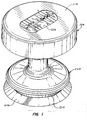
- Fig. 1 is a perspective view of a preferred cardiopulmonary resuscitation device constructed in accordance with the principles of the present invention.
- Fig. 2 is a cross-sectional view of the device of Fig. 1.
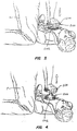
- Figs. 3, and 4 illustrate use of the device of Figs. 1, and 2 by a performer kneeling by a patient, where the performer is using fully-extended arms and applying force through the palms of the performer's hands.
- Figs. 5-7 are schematic illustrations illustrating the internal configuration of the cardiopulmonary resuscitation device of Figs. 1, and 2 during the positioning, compression, and active decompression steps respectively.
-
- According to the present invention, devices are provided for performing manual and automated cardiopulmonary resuscitation (CPR), optionally in combination with electrocardiographic monitoring (ECM) and/or electrical defibrillation as part of advanced cardiac life support (ACLS) procedures. The device comprises an applicator body having an upper surface and a lower surface. The lower surface is adapted to adhere to a patient's chest during the performance of CPR so that the intrathoracic region of the chest can be both compressed by pressing on the applicator body and actively expanded by lifting upward on the applicator body.
- In a specific embodiment of the present invention, the applicator is a vacuum cup (as described in more detail hereinafter) and a handle is attached to an upper surface or wall of a vacuum cup by a connecting stem. The handle preferably includes a pair of generally parallel, transversely spaced-apart gripping surfaces which permit a performer to grasp the handle with two hands, applying force with the palms of the hands and lifting up with fingers which are curled around the gripping surfaces. By "generally parallel," it is meant that the performer will be able to grasp opposite sides of the handle with the palms of the hands facing each other. In a particularly preferred design, the gripping surfaces are located in a plane which is parallel to a contact plane defined by a lower lip of the vacuum cup, i.e., the portion of the vacuum cup which contacts and adheres to the patient. In a second particularly preferred aspect, the vacuum cup includes a reinforcement ring which circumscribes the cup and divides it into a lower flared lip portion and an upper chamber portion. The reinforcement ring maintains the structural integrity of the vacuum cup during use, preventing the cup from deforming to break the vacuum seal when disposed against soft tissue.
- The active expansion of the chest which occurs when the applicator body is lifted causes a negative pressure within the intrathoracic region, drawing air into the lungs to ventilate the patient. This is a particular advantage since it reduces or eliminates the need to otherwise ventilate the patient, such as through mouth-to-mouth resuscitation. In addition, such active expansion causes peripheral blood to move more rapidly back into the right side of the heart and lungs, resulting in increased left heart blood flow during the next compression phase.
- Optionally, the applicator body will include an electrode in its lower surface which can facilitate performance of ECM and/or electrical defibrillation. The stem or other connector will then include wires or other electrical conductors for connecting the electrode(s) to external equipment in a conventional manner.
- The applicator body acts as an interface element between a force-applying source, e.g., the performer's hands, and the sternum region on the patient's chest to which the force is applied. The applicator is designed to both uniformly distribute the applied force over a predetermined area, i.e., the contact area between the applicator and the chest, as well as to provide a cushion to decrease the likelihood of injury resulting from the applied compressive force. Usually, the applicator body will be resilient to provide the desired cushion and may further have the ability to distribute the force uniformly by conforming to the contour of the patient's chest. In addition, the applicator is designed to remain fixed to the chest wall at the desired location for applying compression and expansion, thus eliminating the need to relocate the proper location each time compression is resumed, as is necessary with traditional CPR.
- The preferred embodiment of the applicator body will comprise a resilient vacuum cup having a hollow interior, where the hollow interior is placed against the patients chest so that a vacuum or "suction" is created when the applicator body is compressed thereagainst. Thus, when the vacuum cup structure is subsequently lifted, the patient's chest will be actively expanded. The vacuum cup design is advantageous both because of its inherent adherent characteristics as well as its natural resilience which provides a cushion to protect the patient and promote the even distribution of pressure (force) over the interface region with the patient's chest. Even with the vacuum cup design, it my be desirable to provide an adhesive layer (using the materials described above) over at least a portion of the lip of the vacuum cup which contacts the patient's chest. Adhesive helps hold the vacuum cup applicator body in place and helps assure that the desired vacuum is maintained.
- As an alternative to the adhesive, the vacuum cup may be designed to promote maintenance of vacuum or negative pressure within the cup to enhance adherence and reduce undesired migration of the cup across the patient's chest. Such a design may employ a lower flared lip and an upper bell-shaped chamber. The lower lip and upper chamber are joined at a transition region having a reduced diameter, and a reinforcement ring is located at or just above this reduced diameter transition region. The reinforcement ring will be composed of a rigid material, typically being rigid plastic or metal. The ring may be placed around the exterior surface of the vacuum cup, be molded within the cup, or be placed around the interior of the cup. The presence of the reinforcement ring helps assure that the vacuum cup, which is otherwise composed of an elastomeric material, will not unduly deform during use. In particular, the reinforcement ring prevents the vacuum cup from drawing up soft tissue into its interior and thus permitting an edge of the lip to raise from the tissue and break the internal vacuum.
- It will frequently be desirable to form the applicator body as a laminated or layered structure, usually having one or more upper layers which are rigid relative to the lower layer(s). The relatively rigid upper layer(s) will act to receive a localized compressive force, either from the performer's hand or from a mechanical driver, and to evenly distribute the force over the lower, more resilient layers.
- For manual applicator designs, means for securing at least one hand will be provided on the upper surface of the applicator body. The means for securing can be a strap, mitten, glove, or the like, which permits the performer to both press down on the applicator body and lift upward on the body without the need to grasp the applicator body in any way. The securing means should be attached to the upper surface so that the upward force applied by the performer's hand will be relatively evenly distributed over the applicator body. The use of a relatively rigid upper surface on the applicator body will help provide such even force distribution.
- The dimensions of the applicator body will be chosen to provide a desired interface area between the applicator and the patient's chest. Typically, for adult patients, the applicator will have a circular periphery with a diameter in the range from about 8 to 25 cm, preferably being in the range from about 10 to 20 cm. For children, the dimensions may be as small as 3 cm. Other, non-circular geometries may also find use, and it is necessary only that the applicator body be shaped to provide for a desired force distribution over the patient's sternum as well as to provide for sufficient adherence to allow the patient's chest to be expanded when the applicator body is raised upward.
- The thickness of the applicator body is not critical and will depend on the particular body design. For vacuum cup designs, the maximum thickness, i.e., the maximum air gap, will be in the range from about 1 to 15 cm, more usually from about 5 to 12 cm. For manual applications, it will be desirable to provide a flat upper surface so that the user can press down evenly over the surface with one or both hands in a manner similar to conventional CPR. In this way, the performer will experience the same "feel" as conventional CPR with the advantages of the present invention of patient protection and improved ventilation and circulation. In some cases, it may be desirable to shape the lower surface of the applicator body to conform to the general contours of the human chest. In addition, it may be desirable to provide a plurality of sizes of the applicator in a single kit so that a particular applicator may be selected for the individual patient. Such kits would have applicators as small as about 3 cm in diameter for children to as large as 25 cm, usually 20 cm, in diameter for adults.
- It will frequently be desirable to provide one or more electrodes in the lower surface of the applicator body. The electrodes will be exposed on the surface so that they will contact the patients chest when the applicator body is in use. Usually, when employing electrodes, the lower surface of the applicator will be coated with an adhesive or other material which promotes electrical contact with the skin. For storage, the surface will be covered with a peel-away paper or plastic protective sheet.
- The electrode will be internally connected to an electrical connector or plug, typically located on the side of upper surface of the applicator body. The connector or plug will be selected to allow interconnection with conventional ECM and/or electrical defibrillation equipment. Combination ECM/defibrillation equipment is commercially available from suppliers such as Hewlett-Packard Co., Palo Alto, California, and Physio Control, Seattle, Washington. When used with such systems, the applicator of the present invention can act as one of the two (or more) "paddle" connectors which are secured to the patient's chest for monitoring and/or defibrillation.
- Referring now to Figs. 1, and 2, a particularly preferred embodiment of the cardiopulmonary resuscitation device of the present invention will be described. References made in the description and the claims to "up," "upper," "upwardly," "down," "downward," "downwardly," and the like, will be made with reference to the top and bottom on Figs. 1, and 2. These directions are consistent with the orientation of the device during normal use.
- The
cardiopulmonary resuscitation device 200 includes avacuum cup 202 at its lower end, ahandle structure 204, and a connectingstem structure 206 which joins the vacuum cup to the handle. Thevacuum cup 202 includes a lower flaredlip 208 and an upper bell-shapedchamber 210. The flaredlip 208 andchamber 210 are joined at a reduced diameter juncture ortransition region 212 which circumscribes thevacuum cup 202. Areinforcement ring 214 is disposed just above the juncture or hingeregion 212 and acts to reinforce the shape of theupper chamber 210 and to prevent collapse of thevacuum cup 202 during use. It will be appreciated that the lower flaredlip 208 is highly flexible, and theentire vacuum cup 202 is preferably formed from a soft, elastomeric material, such as silicone rubber. Thelip 208 will thus be able to conform to a wide variety of patient anatomies. As upward and downward forces are applied on theresuscitation device 200, however, there will be a tendency for thevacuum cup 202 to deform and permit the vacuum within the cup to be broken during the upward, decompression stroke on the patient. The presence of thereinforcement ring 214, particularly in combination with the reduceddiameter transition region 212, prevents such deformation and promotes strong adherence of the cup to the patient during the upward expansion stroke. Thevacuum cup 202 further includes a pair of sealingridges 216 formed on the interior surface oflip 208 which further promote maintenance of the vacuum seal of the cup to a patient's chest. In particular, the sealingridges 216 help provide a good vacuum seal even on very hairy chests. - The
handle 204 comprises adisc structure 218, which is illustrated as a unitary body, but will frequently be manufactured in two or more pieces to facilitate assembly. Thedisc structure 218 is molded or otherwise formed to define aperipheral flange 220 which defines a recessedregion 222 which extends annularly around the lower face of thedisc 218. Optionally, thehandle 204 will have a cushioned or padded upper surface for the comfort of the performer. The combination of theflange 220 and recessedregion 222 permits the performer to grasp thehandle 204 by curling the fingers of each hand around the flange and into the recess and placing the palms of the hands against the upper surface. The hands will preferably be located on diametrically opposed portions of the perimeter of thehandle 204. By so grasping thehandle 204 with fully extended arms, a performer can maintain theresuscitation device 200 in a highly stable manner during use. That is, there will be a minimum tendency for the performer to lose control of thedevice 200 and for the device to roll over out of vertical alignment or to migrate out of position on the patient's sternum. - In a preferred construction, a
pressure gauge 224 is mounted in the central region of the upper surface ofhandle structure 204. Conveniently, thepressure gauge 224 provides a positive and negative force scale which permits the user to monitor how much force is being applied in both an upward and downward direction. As illustrated, the downward scale reads from 0 (i.e., no upward or downward force being applied) to 50 kg, while the upward force scale reads from 0 to 15 kg. The device may also include printed constructions for use on the handle, such as about the handle periphery. - The connecting
stem structure 206 includes both aflange 226 on the lower surface of thehandle 204 and aflange 228 on the upper surface or wall of thevacuum cup 202. Astem cylinder 230 is received in theflange 228 on thevacuum cup 202, with its opposite end slidably received in theflange 226 onhandle 204. Thevacuum cup 202 will be detachably mounted on thestem cylinder 230, usually with theflange 228 having aridge 229 received in an annular channel in the stem to permit replacement of the vacuum cup after use. Aspring 232 is connected to and extends between both thevacuum cup 202 and handle 204, and it will be appreciated that thehandle 204 may thus move upward and downward relatively to thevacuum cup 202 during use. A connectingrod 234 also extends between thevacuum cup 202 and handle 204 and, together with thespring 232, forms part of thepressure gauge mechanism 224. - Referring now to Figs. 3, and 4, the
resuscitation device 200 is used as follows. A performer P grasps thehandle 204 in both hands, pressing the palms of the hands against the upper surface while grasping theperipheral flange 220 with the fingers. The performer P locates thevacuum cup 202 on the patient's sternum and begins the procedure by pressing downwardly, typically using a force in the range from about 30 kg to 50 kg, depending on the stiffness of the chest. Sufficient pressure should be used to obtain the desired chest compression depth of about 38 mm to 51 mm. - After the compression stroke is completed, the performer P will raise the
resuscitation device 200, typically using a rocking motion relying on the muscles in the thighs to raise the device. Thedevice 200 will be raised in an amount sufficient to apply an expansion force in the range from about 10 kg to 15 kg. The compression and expansion steps will be alternated at a rate in the range from about 80 to 100 per minute. - Referring now to Figs. 5-7, use of the
device 200 in resuscitating a patient will be further described. The device is initially placed in patient's mid-sternum S, as illustrated in Fig. 5. The performer P then applies sufficient downward force on the handle ofdevice 200 so that the chest is compressed, typically by a distance in the range from 38 mm to 51 mm, as illustrated in Fig. 6. In particular, a contact pad 231 (which is preferably formed in the upper surface of thevacuum cup 202 and which is directly engaged by the lower end of the stem structure 206) ofdevice 200 is lowered to engage the sternum S with the preferred contact area in the range from about 6 cm2 to 40 cm2. Thecontact pad 231 will be formed of a resilient material, typically silicone rubber, and softens the application of downward force through thestem structure 206. The initial position of the patient's chest is illustrated in broken line in Fig. 6. During the compression stroke, the internal volume of the vacuum cup ofdevice 200 is reduced by collapsing the upper surface down, as illustrated in Fig. 6. The flared lower lip ofdevice 200 allows air to readily escape during the compression stroke. - After the compression stroke is completed, the performer P immediately raises on the
handle 204 ofdevice 200 to expand the chest, as illustrated in Fig. 7. Again, the rest position of the chest is illustrated in broken line. During the chest expansion stroke, the vacuum or negative pressure will be created within the interior volume of thevacuum cup 202. Such negative pressure will cause adherence of thedevice 200 to the chest to permit the desired expansion. The presence of thereinforcement ring 214 will help prevent significant deformation of the vacuum cup which might permit loss of vacuum which is required for performance of the procedure. The particular design of thevacuum cup 202, including theupper chamber 214, lower flaredlip 208, andreinforcement ring 214, is particularly desirable since it allows for the vacuum within the vacuum cup to be renewed on each compression stroke. In this way, use of the device is highly reliable with any tendency for the device to lose vacuum or to migrate across the patient's chest greatly reduced. - Although the foregoing invention has been described in detail for purposes of clarity of understanding, it will be obvious that certain modifications may be practiced within the scope of the appended claims.
Claims (7)
- A cardiopulmonary resuscitation device comprising:a vacuum cup (202) composed of an elastomeric material having a lower lip (208) joined by a reduced diameter juncture (212) with an upper wall having a horizontal lower surface; a connecting stem (206) having an upper and a lower end, wherein the lower end (231) is attached to a central region of the upper wall anda handle (204) attached to the upper end of the connecting stem (206),
characterized in thatthe upper wall is so flexible that by applying a downward force in the range from 294,2 N (30 kg) to 490,3 N (50 kg) on the connecting stem the upper wall collapses to engage a horizontal lower surface of the central region having an area in the range from 6 cm2 to 40 cm2 with the patient's sternum to cause chest compression and upward force can actively expand the patient's chest. - A cardiopulmonary resuscitation device as in claim 1, wherein the vacuum cup includes an upper chamber (210) and a flared lower lip (208), further comprising a reinforcement ring (214) circumscribing the vacuum cup above the flared lower lip.
- A cardiopulmonary resuscitation device as in claim 1, wherein the connecting stem (206) comprises an upper section (226) attached to a lower surface of the handle and a lower section (228) attached to the vacuum cup, wherein the upper and lower sections are joined in a telescoping manner, further comprising a spring (232) extending between the upper and lower sections.
- A cardiopulmonary resuscitation device as in claim 1, wherein the lower lip (208) of the vacuum cup is disposed in a plane and the handle (204) includes a pair of generally parallel, transversely spaced-apart gripping surfaces, located in a plane parallel to the contact plane and wherein the gripping surfaces each have an upper flat surface, a rounded outer edge, and an undercut lower surface, wherein the handle can be gripped by placing the palms of the hand against the upper flat surface and wrapping the fingers around the edge and into the undercut.
- A cardiopulmonary resuscitation device as in claim 4, wherein the handle (204) has a circular periphery and wherein the gripping surfaces are defined continuously over said circular periphery of the handle.
- A cardiopulmonary resuscitation device as in claim 5, wherein the handle (204) is a disc attached at the center of its lower surface to the connecting stem (206), further comprising a pressure gauge (224) mounted in the center of the upper surface of the disc handle, whereby it is visible to a performer grasping diametrically opposed peripheral sections.
- A cardiopulmonary resuscitation device as in claim 1, further comprising sealing ridges (216) formed circumferentially about an inner surface of the lower lip (208) of the vacuum cup.
Applications Claiming Priority (2)
| Application Number | Priority Date | Filing Date | Title |
|---|---|---|---|
| US58195 | 1993-05-04 | ||
| US08/058,195 US5645522A (en) | 1991-04-17 | 1993-05-04 | Devices and methods for controlled external chest compression |
Publications (2)
| Publication Number | Publication Date |
|---|---|
| EP0623334A1 EP0623334A1 (en) | 1994-11-09 |
| EP0623334B1 true EP0623334B1 (en) | 1999-06-09 |
Family
ID=22015299
Family Applications (1)
| Application Number | Title | Priority Date | Filing Date |
|---|---|---|---|
| EP94106492A Expired - Lifetime EP0623334B1 (en) | 1993-05-04 | 1994-04-26 | Cardiopulmonary resuscitation device |
Country Status (9)
| Country | Link |
|---|---|
| US (1) | US5645522A (en) |
| EP (1) | EP0623334B1 (en) |
| JP (1) | JP3072318B2 (en) |
| AT (1) | ATE180963T1 (en) |
| AU (1) | AU687379B2 (en) |
| BR (1) | BR9401638A (en) |
| CA (1) | CA2117275C (en) |
| DE (1) | DE69418937T2 (en) |
| ES (1) | ES2132274T3 (en) |
Cited By (2)
| Publication number | Priority date | Publication date | Assignee | Title |
|---|---|---|---|---|
| US7226427B2 (en) | 2003-05-12 | 2007-06-05 | Jolife Ab | Systems and procedures for treating cardiac arrest |
| US7569021B2 (en) | 2002-03-21 | 2009-08-04 | Jolife Ab | Rigid support structure on two legs for CPR |
Families Citing this family (123)
| Publication number | Priority date | Publication date | Assignee | Title |
|---|---|---|---|---|
| US7082945B2 (en) * | 2003-04-28 | 2006-08-01 | Advanced Circulatory Systems, Inc. | Ventilator and methods for treating head trauma |
| US6425393B1 (en) | 1993-11-09 | 2002-07-30 | Cprx Llc | Automatic variable positive expiratory pressure valve and methods |
| US7195012B2 (en) * | 2003-04-28 | 2007-03-27 | Advanced Circulatory Systems, Inc. | Systems and methods for reducing intracranial pressure |
| US7195013B2 (en) * | 1993-11-09 | 2007-03-27 | Advanced Circulatory Systems, Inc. | Systems and methods for modulating autonomic function |
| US6604523B2 (en) * | 1993-11-09 | 2003-08-12 | Cprx Llc | Apparatus and methods for enhancing cardiopulmonary blood flow and ventilation |
| DE4443675A1 (en) * | 1994-12-08 | 1996-06-13 | Norbert Dr Med Huser | Device for heart resuscitation |
| US5935136A (en) * | 1997-05-09 | 1999-08-10 | Pristech, Inc. | Obstetrical vacuum extractor cup with soft molded lip |
| US6174295B1 (en) | 1998-10-16 | 2001-01-16 | Elroy T. Cantrell | Chest mounted cardio pulmonary resuscitation device and system |
| JP4741720B2 (en) | 1997-11-06 | 2011-08-10 | コーニンクレッカ フィリップス エレクトロニクス エヌ ヴィ | Defibrillator giving a synchronous CPR prompt |
| US6013041A (en) * | 1998-02-13 | 2000-01-11 | Leathers; Kevin P. | Apparatus and method for simulating therapeutic manipulation |
| US6234985B1 (en) | 1998-06-11 | 2001-05-22 | Cprx Llc | Device and method for performing cardiopulmonary resuscitation |
| US6312399B1 (en) | 1998-06-11 | 2001-11-06 | Cprx, Llc | Stimulatory device and methods to enhance venous blood return during cardiopulmonary resuscitation |
| US6463327B1 (en) | 1998-06-11 | 2002-10-08 | Cprx Llc | Stimulatory device and methods to electrically stimulate the phrenic nerve |
| US6155257A (en) * | 1998-10-07 | 2000-12-05 | Cprx Llc | Cardiopulmonary resuscitation ventilator and methods |
| EP1128794A2 (en) * | 1998-11-09 | 2001-09-05 | The Johns Hopkins University | Automated chest compression apparatus |
| NO311746B1 (en) * | 1999-08-27 | 2002-01-21 | Laerdal Medical As | System for reducing signal interference in ECG caused by cardiac lung rescue |
| JP2003521355A (en) | 2000-02-04 | 2003-07-15 | ゼットエムデー コーポレイション | Integrated resuscitation |
| US20060064131A1 (en) * | 2000-02-04 | 2006-03-23 | Freeman Gary A | User interface for defibrillator for use by persons with limited training and experience |
| US20050131465A1 (en) | 2000-02-04 | 2005-06-16 | Freeman Gary A. | Integrated resuscitation |
| AU2001249233A1 (en) * | 2000-03-22 | 2001-10-03 | Advanced Circulatory Systems, Inc. | CPR mask with compression timing metronome and methods |
| US6427685B1 (en) | 2000-03-27 | 2002-08-06 | Ray, Ii Philip W. | Device to facilitate the performance of cardiopulmonary resuscitation |
| US20020002346A1 (en) * | 2000-06-29 | 2002-01-03 | Horst Patricia J. | Apparatus and method of massaging back and alleviating back pain using suction cup |
| AU2002256446A1 (en) * | 2001-05-11 | 2002-11-25 | Advanced Circulatory Systems, Inc. | Cardiopulmonary resuscitation chest compression/decompression device with electronic stethoscope |
| US6776156B2 (en) | 2001-09-28 | 2004-08-17 | Advanced Circulatory Systems, Inc. | Systems and methods to facilitate the delivery of drugs |
| JP2003169829A (en) * | 2001-12-06 | 2003-06-17 | Hidenori Hagiwara | Suction cup for slimming |
| US6726639B2 (en) * | 2002-01-16 | 2004-04-27 | Jorge I. Bassuk | Medical cuirass for cardio-pulmonary resuscitation |
| US7682312B2 (en) * | 2002-09-20 | 2010-03-23 | Advanced Circulatory Systems, Inc. | System for sensing, diagnosing and treating physiological conditions and methods |
| US6863656B2 (en) | 2002-09-20 | 2005-03-08 | Advanced Circulatory Systems, Inc. | Stress test devices and methods |
| NO317846B1 (en) * | 2002-12-23 | 2004-12-20 | Laerdal Medical As | Device for placement on the chest of a patient, to interact with the hands of a person performing chest compressions. |
| US20040162510A1 (en) * | 2003-02-14 | 2004-08-19 | Medtronic Physio-Control Corp | Integrated external chest compression and defibrillation devices and methods of operation |
| US7044128B2 (en) * | 2003-04-08 | 2006-05-16 | Advanced Circulatory Systems, Inc. | CPR demonstration device and methods |
| EP3064242A1 (en) | 2003-04-28 | 2016-09-07 | Advanced Circulatory Systems Inc. | Ventilator and methods for treating head trauma and low blood circulation |
| US7836881B2 (en) | 2003-04-28 | 2010-11-23 | Advanced Circulatory Systems, Inc. | Ventilator and methods for treating head trauma and low blood circulation |
| US7766011B2 (en) * | 2003-04-28 | 2010-08-03 | Advanced Circulatory Systems, Inc. | Positive pressure systems and methods for increasing blood pressure and circulation |
| US20080047555A1 (en) * | 2003-09-11 | 2008-02-28 | Advanced Circulatory Systems, Inc. | Bag-valve resuscitation for treating of hypotension, head trauma, and cardiac arrest |
| US6938618B2 (en) | 2003-09-11 | 2005-09-06 | Advanced Circulatory Systems, Inc. | Bag-valve resuscitation for treatment of hypotention, head trauma, and cardiac arrest |
| US8011367B2 (en) * | 2003-09-11 | 2011-09-06 | Advanced Circulatory Systems, Inc. | CPR devices and methods utilizing a continuous supply of respiratory gases |
| US7211056B2 (en) * | 2004-08-28 | 2007-05-01 | Danuta Grazyna Petelenz | Device for chest and abdominal compression CPR |
| EP1858472B1 (en) * | 2005-02-15 | 2013-08-28 | Laerdal Medical AS | Standalone system for assisting in a life-saving situation |
| US7909784B2 (en) * | 2005-06-03 | 2011-03-22 | Kornaker Kathleen M | Cardiopulmonary assist device |
| WO2007011798A2 (en) * | 2005-07-15 | 2007-01-25 | Lach Thomas E | Cross action chest compression apparatus for cardiac arrest |
| US7650181B2 (en) | 2005-09-14 | 2010-01-19 | Zoll Medical Corporation | Synchronization of repetitive therapeutic interventions |
| US7361151B2 (en) * | 2005-10-13 | 2008-04-22 | Wood Harrill D | Device and kit for assisting in cardiopulmonary resuscitations |
| US8452393B1 (en) * | 2005-11-07 | 2013-05-28 | Stephen T. Epstein | Defibrillation paddle structure and its associated method of use |
| DE602005022602D1 (en) * | 2005-12-21 | 2010-09-09 | Zadeh David Khorassani | Device for massage with constant pressure |
| US8010190B2 (en) | 2006-05-26 | 2011-08-30 | Cardiac Science Corporation | CPR feedback method and apparatus |
| WO2008045442A2 (en) * | 2006-10-06 | 2008-04-17 | Karen Holm | Cough assistance and airway clearance device |
| TWI360416B (en) | 2006-12-14 | 2012-03-21 | Ind Tech Res Inst | Apparatus of cardiopulmonary resuscitator |
| US9028259B2 (en) | 2007-01-16 | 2015-05-12 | Physio-Control, Inc. | Wearable CPR assist, training and testing device |
| US8151790B2 (en) * | 2007-04-19 | 2012-04-10 | Advanced Circulatory Systems, Inc. | Volume exchanger valve system and method to increase circulation during CPR |
| US9352111B2 (en) | 2007-04-19 | 2016-05-31 | Advanced Circulatory Systems, Inc. | Systems and methods to increase survival with favorable neurological function after cardiac arrest |
| AU2008259899A1 (en) * | 2007-06-01 | 2008-12-11 | Cardiac Science Corporation | System, method, and apparatus for assisting a rescuer in resuscitation |
| EP2192884B1 (en) * | 2007-09-21 | 2016-08-24 | Koninklijke Philips N.V. | Cpr monitoring and reporting system |
| US20090234255A1 (en) * | 2008-03-12 | 2009-09-17 | Votel Thomas W | Ergonomic device for administering cardio-pulmonary resuscitation |
| US9724266B2 (en) * | 2010-02-12 | 2017-08-08 | Zoll Medical Corporation | Enhanced guided active compression decompression cardiopulmonary resuscitation systems and methods |
| WO2011100694A1 (en) * | 2010-02-12 | 2011-08-18 | Advanced Circulatory Systems, Inc. | Guided active compression decompression cardiopulmonary resuscitation systems and methods |
| US12016820B2 (en) | 2010-02-12 | 2024-06-25 | Zoll Medical Corporation | Enhanced guided active compression decompression cardiopulmonary resuscitation systems and methods |
| WO2011112820A2 (en) * | 2010-03-11 | 2011-09-15 | Ortho-Neuro Technologies, Inc. | Therapeutic manipulation device |
| US9687415B2 (en) * | 2010-05-13 | 2017-06-27 | The Nemours Foundation | Extrathoracic augmentation of the respiratory pump |
| JP5309399B2 (en) * | 2010-06-10 | 2013-10-09 | 株式会社メトラン | Automatic chest compression device |
| CN103189021A (en) * | 2010-09-09 | 2013-07-03 | 原田正则 | Chiropractic device capable of forming relief surface |
| KR101024617B1 (en) * | 2010-12-09 | 2011-03-29 | 박정길 | Portable cardiopulmonary resuscitation device |
| DE102011014304A1 (en) * | 2011-03-17 | 2012-09-20 | GS-Elektromedizinische Geräte, G. Stemple GmbH | Device for resuscitating a patient |
| US8535251B1 (en) | 2011-04-04 | 2013-09-17 | Subhakar Patthi Rao | Mechanical device to assist in the external compression of the chest during cardio-pulmonary resuscitation |
| US20120310123A1 (en) * | 2011-04-16 | 2012-12-06 | Moessmer Sebastian | Device and method for controlled heart-lung-reanimation when the heart stops |
| US20130030333A1 (en) * | 2011-07-27 | 2013-01-31 | Cicenas Chris W | Manual CPR apparatus with force multiplier |
| US20140213942A1 (en) * | 2011-08-25 | 2014-07-31 | Joseph Hanson | Cardiopulmonary resuscitation device |
| US9119767B2 (en) | 2011-09-13 | 2015-09-01 | Harrill D. Wood | Manual CPR or CCC continuous chest compression assist device |
| CN102499874A (en) * | 2011-10-28 | 2012-06-20 | 中国人民解放军第四军医大学 | Portable stretcher type external chest compression resuscitation device |
| EP2793985B1 (en) | 2011-12-19 | 2019-07-17 | Zoll Medical Corporation | Systems and methods for therapeutic intrathoracic pressure regulation |
| SI23964A (en) | 2012-01-30 | 2013-07-31 | Ivor Ković | Cardiopulmonary resuscitation device for high quality external chest compression |
| US8942800B2 (en) | 2012-04-20 | 2015-01-27 | Cardiac Science Corporation | Corrective prompting system for appropriate chest compressions |
| US11590053B2 (en) | 2012-05-17 | 2023-02-28 | Zoll Medical Corporation | Cameras for emergency rescue |
| US9522096B2 (en) * | 2012-05-17 | 2016-12-20 | Zoll Medical Corporation | CPR team performance |
| US10420701B2 (en) | 2013-05-17 | 2019-09-24 | Zoll Medical Corporation | Cameras for emergency rescue |
| US20140046227A1 (en) * | 2012-07-25 | 2014-02-13 | Hayden R Fleming | Chest containment system and method |
| US20140072940A1 (en) * | 2012-09-10 | 2014-03-13 | Harrill D. Wood | Cpr training device and method of use |
| WO2014051551A1 (en) * | 2012-09-25 | 2014-04-03 | Joseph Hanson | Cardiopulmonary resuscitation device and method of use |
| US8920348B2 (en) * | 2012-09-28 | 2014-12-30 | Zoll Medical Corporation | Method and device for performing alternating chest compression and decompression |
| US20140100496A1 (en) * | 2012-10-09 | 2014-04-10 | Physio-Control, Inc. | Devices and methods for performing cpr while standing up |
| US9713568B2 (en) | 2012-12-21 | 2017-07-25 | Physio-Control, Inc. | Mechanical CPR device with automatic suction cup attachment |
| US9811634B2 (en) | 2013-04-25 | 2017-11-07 | Zoll Medical Corporation | Systems and methods to predict the chances of neurologically intact survival while performing CPR |
| US20140323928A1 (en) | 2013-04-30 | 2014-10-30 | Zoll Medical Corporation | Compression Depth Monitor with Variable Release Velocity Feedback |
| US20140358047A1 (en) | 2013-05-30 | 2014-12-04 | ResQSystems, Inc. | End-tidal carbon dioxide and amplitude spectral area as non-invasive markers of coronary perfusion pressure and arterial pressure |
| US20150088016A1 (en) | 2013-09-25 | 2015-03-26 | Zoll Medical Corporation | Mobile Device Control |
| US10265495B2 (en) | 2013-11-22 | 2019-04-23 | Zoll Medical Corporation | Pressure actuated valve systems and methods |
| US11259988B2 (en) | 2014-02-19 | 2022-03-01 | Keith G. Lurie | Active compression decompression and upper body elevation system |
| US11020314B2 (en) | 2014-02-19 | 2021-06-01 | Keith G. Lurie | Methods and systems to reduce brain damage |
| US10406069B2 (en) | 2014-02-19 | 2019-09-10 | Keith G. Lurie | Device for elevating the head and chest for treating low blood flow states |
| US11096861B2 (en) | 2014-02-19 | 2021-08-24 | Keith G. Lurie | Systems and methods for gravity-assisted cardiopulmonary resuscitation and defibrillation |
| US9750661B2 (en) | 2014-02-19 | 2017-09-05 | Keith G. Lurie | Systems and methods for head up cardiopulmonary resuscitation |
| US10667987B2 (en) | 2014-02-19 | 2020-06-02 | Keith G. Lurie | Uniform chest compression CPR |
| US9707152B2 (en) | 2014-02-19 | 2017-07-18 | Keith G. Lurie | Systems and methods for head up cardiopulmonary resuscitation |
| US10406068B2 (en) | 2014-02-19 | 2019-09-10 | Keith G. Lurie | Lockable head up cardiopulmonary resuscitation support device |
| US10350137B2 (en) | 2014-02-19 | 2019-07-16 | Keith G. Lurie | Elevation timing systems and methods for head up CPR |
| US10245209B2 (en) | 2014-02-19 | 2019-04-02 | Keith G. Lurie | Systems and methods for gravity-assisted cardiopulmonary resuscitation |
| US9801782B2 (en) | 2014-02-19 | 2017-10-31 | Keith G. Lurie | Support devices for head up cardiopulmonary resuscitation |
| US11844742B2 (en) | 2014-02-19 | 2023-12-19 | Keith G. Lurie | Methods and systems to reduce brain damage |
| US11246794B2 (en) | 2014-02-19 | 2022-02-15 | Keith G. Lurie | Systems and methods for improved post-resuscitation recovery |
| US10004662B2 (en) | 2014-06-06 | 2018-06-26 | Physio-Control, Inc. | Adjustable piston |
| US11246796B2 (en) * | 2014-06-06 | 2022-02-15 | Physio-Control, Inc. | Adjustable piston |
| US10092464B2 (en) | 2014-10-03 | 2018-10-09 | Physio-Control, Inc. | Medical device stabilization strap |
| EP3220873B1 (en) * | 2014-11-17 | 2022-06-22 | Physio-Control, Inc. | Cpr chest compression machine adjusting motion-time profile in view of detected force |
| DE102014014074B4 (en) * | 2014-12-05 | 2018-05-24 | Inotech Kunststofftechnik Gmbh | Multi-part device for controlled cardiopulmonary resuscitation during cardiac arrest |
| WO2016149680A1 (en) * | 2015-03-18 | 2016-09-22 | Cardiospark Llc | Compact, portable defibrillator and related methods |
| DE102015006540A1 (en) * | 2015-05-27 | 2016-12-01 | Dominic Oliver Dussault | Device for assisting a user in cardiopulmonary resuscitation |
| US10478375B2 (en) * | 2015-09-25 | 2019-11-19 | Peter Antros | Pulmonary expansion therapy devices |
| US10004912B1 (en) | 2016-07-27 | 2018-06-26 | Cardiospark Llc | System and method for diagnosing and treating cardiac arrhythmia |
| US10682511B2 (en) | 2016-08-05 | 2020-06-16 | Stephen T. Epstein | Defibrillator for minimally invasive surgical procedures |
| US10092767B1 (en) | 2016-08-11 | 2018-10-09 | Cardiospark Llc | System and method for network-enabled automatic electronic defibrillators |
| US10780020B2 (en) | 2016-09-30 | 2020-09-22 | Zoll Medical Corporation | Maintaining active compression decompression device adherence |
| US20180098911A1 (en) * | 2016-10-07 | 2018-04-12 | Sharon James | Device and method for chest physiotherapy treatment |
| CN106798636B (en) * | 2017-03-03 | 2023-08-15 | 苏州尚领医疗科技有限公司 | Rebound release mechanism for cardiopulmonary resuscitation |
| CN107343847B (en) * | 2017-07-05 | 2019-09-20 | 孙奕 | A kind of light heart compressions instrument |
| US11179293B2 (en) | 2017-07-28 | 2021-11-23 | Stryker Corporation | Patient support system with chest compression system and harness assembly with sensor system |
| US10590638B2 (en) * | 2017-09-17 | 2020-03-17 | Syneco, LLC | Toilet plunger |
| CA3086201A1 (en) | 2017-12-21 | 2019-06-27 | Keith G. Lurie | Device for elevating the head and chest for treating low blood flow states |
| CN109620695B (en) * | 2019-01-17 | 2021-07-16 | 陕西能源职业技术学院 | Medical heartbeat detection restorer |
| EP3735954A1 (en) * | 2019-05-06 | 2020-11-11 | Koninklijke Philips N.V. | Cardiopulmonary resuscitation device, control method and computer program |
| EP3735955A1 (en) * | 2019-05-06 | 2020-11-11 | Koninklijke Philips N.V. | Cardiopulmonary resuscitation device, control method and computer program |
| USD926323S1 (en) | 2020-03-30 | 2021-07-27 | Zoll Medical Corporation | Automated external defibrillator electrode pad |
| KR102502730B1 (en) * | 2020-09-29 | 2023-02-23 | 동남보건대학교 산학협력단 | Close-up manual chest compression aid device |
| CN112603620B (en) * | 2020-12-30 | 2023-03-24 | 中南大学湘雅二医院 | Heart surgical nursing device |
Citations (1)
| Publication number | Priority date | Publication date | Assignee | Title |
|---|---|---|---|---|
| EP0509773A1 (en) * | 1991-04-17 | 1992-10-21 | The Regents Of The University Of California | Device for external chest compression |
Family Cites Families (39)
| Publication number | Priority date | Publication date | Assignee | Title |
|---|---|---|---|---|
| US1193476A (en) * | 1916-08-01 | Office | ||
| US517481A (en) * | 1894-04-03 | Device for producing respiration | ||
| US219428A (en) * | 1879-09-09 | Improvement in devices for clearing obstructions from pipes | ||
| US728003A (en) * | 1902-06-14 | 1903-05-12 | Charles Pfanschmidt | Massage-cup. |
| US1175671A (en) * | 1915-06-21 | 1916-03-14 | Thomas Engleman Acklen | Resuscitator. |
| US1460927A (en) * | 1922-03-28 | 1923-07-03 | Ralph S Thompson | Vacuum cup |
| GB274306A (en) * | 1926-09-17 | 1927-07-21 | Beatrice Evelyn Thomlinson | Improved appliance for massaging the body |
| DE468358C (en) * | 1927-02-08 | 1928-11-12 | Fritz Kuhn Dr | Device for deep pressure massage of the abdominal organs for self-application |
| DE620594C (en) * | 1934-03-24 | 1935-10-24 | Hans Hans Dr | Resuscitation device |
| US2128217A (en) * | 1937-06-23 | 1938-08-30 | Anderson Olof | Drain plunger |
| US2204738A (en) * | 1938-08-15 | 1940-06-18 | Harry L Swan | Resuscitator |
| US2406317A (en) * | 1945-04-16 | 1946-08-27 | Bonde Gust | Double suction plunger |
| CH256694A (en) * | 1947-07-26 | 1948-08-31 | A Stuessi | Massager. |
| DE804025C (en) * | 1948-10-02 | 1951-04-16 | Dr Hans Hans Sen | Resuscitation device for seemingly dead newborns |
| US2742251A (en) * | 1952-12-30 | 1956-04-17 | Udvardy Zolton | Support for self-massaging device |
| US2879765A (en) * | 1957-06-25 | 1959-03-31 | Paul V Featherston | Therapeutic device |
| US3138803A (en) * | 1962-03-28 | 1964-06-30 | Caplan Charles | Pressurized plunger |
| US3228392A (en) * | 1963-07-15 | 1966-01-11 | Walter L Speyer | Abdominal exerciser |
| FR1476518A (en) * | 1964-12-30 | 1967-04-14 | Systolo-diastolic prosthesis for external cardiac massage with assisted breathing | |
| GB1187274A (en) * | 1967-04-03 | 1970-04-08 | Matburn Holdings Ltd | Cardiac Massage Apparatus |
| GB1237230A (en) * | 1968-01-04 | 1971-06-30 | Giuseppe Parodi Fu Leonardo | A device for clearing blockages in the outlets of sinks, baths or the like |
| US3534733A (en) * | 1968-01-10 | 1970-10-20 | Us Navy | Spring-loaded suction cup-type biomedical instrumentation electrode |
| US3783865A (en) * | 1971-11-08 | 1974-01-08 | Marquette Electronics Inc | Suction electrode |
| US4077400A (en) * | 1975-01-17 | 1978-03-07 | Roy Major Harrigan | External cardiac resuscitation aid |
| US4166458A (en) * | 1975-01-17 | 1979-09-04 | Harrigan Roy Major | External cardiac resuscitation aid |
| US3958564A (en) * | 1975-05-09 | 1976-05-25 | The United States Of America As Represented By The Secretary Of The Navy | EKG contact |
| US3994032A (en) * | 1975-08-20 | 1976-11-30 | Lawrence Peska Associates, Inc. | Drain clearing bellows |
| US4095590A (en) * | 1975-08-29 | 1978-06-20 | Roy Major Harrigan | External cardiac resuscitation aid |
| US4059099A (en) * | 1976-04-13 | 1977-11-22 | Davis Belford L | Resuscitative device |
| US4198963A (en) * | 1978-10-19 | 1980-04-22 | Michigan Instruments, Inc. | Cardiopulmonary resuscitator, defibrillator and monitor |
| US4196722A (en) * | 1979-01-05 | 1980-04-08 | Vanderwoude Carol A | Percussion instrument used in respiratory therapy |
| US4237872A (en) * | 1979-04-30 | 1980-12-09 | Harrigan Roy Major | External cardiac resuscitation aid |
| US4429688A (en) * | 1980-12-08 | 1984-02-07 | Duffy Peter B | Medical appliance for percussive respiratory therapy |
| US4554910A (en) * | 1983-02-28 | 1985-11-26 | Health Education Publication Company, Inc. | Cardio pulmonary resuscitation pressure indicator |
| GB8316194D0 (en) * | 1983-06-14 | 1983-07-20 | Medeci Developments Ltd | Electrode holders for current therapy |
| US4881527A (en) * | 1988-11-14 | 1989-11-21 | Lerman Samuel I | Cardiac assist cuirass |
| US5114006A (en) * | 1990-04-05 | 1992-05-19 | Wilk Peter J | Tool assembly |
| US5295481A (en) * | 1991-11-01 | 1994-03-22 | Geeham Calvin T | Cardiopulmonary resuscitation assist device |
| US5239708A (en) * | 1992-05-21 | 1993-08-31 | Lawrence Irwin F | Pneumatic waste line clean-out tool |
-
1993
- 1993-05-04 US US08/058,195 patent/US5645522A/en not_active Expired - Lifetime
-
1994
- 1994-04-14 CA CA002117275A patent/CA2117275C/en not_active Expired - Lifetime
- 1994-04-18 AU AU60539/94A patent/AU687379B2/en not_active Expired
- 1994-04-26 AT AT94106492T patent/ATE180963T1/en active
- 1994-04-26 EP EP94106492A patent/EP0623334B1/en not_active Expired - Lifetime
- 1994-04-26 ES ES94106492T patent/ES2132274T3/en not_active Expired - Lifetime
- 1994-04-26 DE DE69418937T patent/DE69418937T2/en not_active Expired - Lifetime
- 1994-04-28 BR BR9401638A patent/BR9401638A/en not_active IP Right Cessation
- 1994-05-06 JP JP6094478A patent/JP3072318B2/en not_active Expired - Lifetime
Patent Citations (1)
| Publication number | Priority date | Publication date | Assignee | Title |
|---|---|---|---|---|
| EP0509773A1 (en) * | 1991-04-17 | 1992-10-21 | The Regents Of The University Of California | Device for external chest compression |
Cited By (3)
| Publication number | Priority date | Publication date | Assignee | Title |
|---|---|---|---|---|
| US7569021B2 (en) | 2002-03-21 | 2009-08-04 | Jolife Ab | Rigid support structure on two legs for CPR |
| US9107800B2 (en) | 2002-03-21 | 2015-08-18 | Physio-Control, Inc. | Front part for support structure for CPR |
| US7226427B2 (en) | 2003-05-12 | 2007-06-05 | Jolife Ab | Systems and procedures for treating cardiac arrest |
Also Published As
| Publication number | Publication date |
|---|---|
| CA2117275C (en) | 2001-10-16 |
| BR9401638A (en) | 1994-12-20 |
| AU687379B2 (en) | 1998-02-26 |
| JP3072318B2 (en) | 2000-07-31 |
| CA2117275A1 (en) | 1994-11-05 |
| AU6053994A (en) | 1994-11-10 |
| EP0623334A1 (en) | 1994-11-09 |
| ATE180963T1 (en) | 1999-06-15 |
| US5645522A (en) | 1997-07-08 |
| DE69418937T2 (en) | 2000-03-16 |
| ES2132274T3 (en) | 1999-08-16 |
| DE69418937D1 (en) | 1999-07-15 |
| JPH06343701A (en) | 1994-12-20 |
Similar Documents
| Publication | Publication Date | Title |
|---|---|---|
| EP0623334B1 (en) | Cardiopulmonary resuscitation device | |
| EP0509773B1 (en) | Device for external chest compression | |
| US5295481A (en) | Cardiopulmonary resuscitation assist device | |
| US7186225B2 (en) | Chest compression apparatus for cardiac arrest | |
| EP1622562B1 (en) | System for treating cardiac arrest | |
| US7361151B2 (en) | Device and kit for assisting in cardiopulmonary resuscitations | |
| EP2900194B1 (en) | Cardiopulmonary resuscitation device | |
| AU748550B2 (en) | A device for assisted cardiopulmonary resuscitation | |
| US5383786A (en) | Training manikin for practicing external cardiac massage | |
| US20110201979A1 (en) | Guided active compression decompression cardiopulmonary resuscitation systems and methods | |
| ZA200509157B (en) | Systems and procedures for treating cardiac arrest | |
| US8622940B2 (en) | Device for assisting cardiac pulmonary resuscitation | |
| Halperin et al. | New approaches to CPR: four hands, a plunger, or a vest | |
| EP3737348B1 (en) | Equipment for use when giving heart massage | |
| CN219332467U (en) | Auxiliary pad for pressing sternum for emergency | |
| CN221534763U (en) | Palm pad of wearing CPR equipment | |
| JPH0137626Y2 (en) | ||
| Paul et al. | Design of auto adjustable CPR assistive device for non-expertise usability scenarios | |
| HU217941B (en) | Revivificating device for ensuring active compression and decompression | |
| MXPA98004757A (en) | Apparatus to compress the chest, to treat a cardi stop |
Legal Events
| Date | Code | Title | Description |
|---|---|---|---|
| PUAI | Public reference made under article 153(3) epc to a published international application that has entered the european phase |
Free format text: ORIGINAL CODE: 0009012 |
|
| AK | Designated contracting states |
Kind code of ref document: A1 Designated state(s): AT BE CH DE DK ES FR GB GR IE IT LI LU MC NL PT SE |
|
| 16A | New documents despatched to applicant after publication of the search report | ||
| 17P | Request for examination filed |
Effective date: 19941207 |
|
| 17Q | First examination report despatched |
Effective date: 19960321 |
|
| GRAG | Despatch of communication of intention to grant |
Free format text: ORIGINAL CODE: EPIDOS AGRA |
|
| RAP1 | Party data changed (applicant data changed or rights of an application transferred) |
Owner name: AMBU INTERNATIONAL A/S Owner name: THE REGENTS OF THE UNIVERSITY OF CALIFORNIA |
|
| GRAG | Despatch of communication of intention to grant |
Free format text: ORIGINAL CODE: EPIDOS AGRA |
|
| GRAH | Despatch of communication of intention to grant a patent |
Free format text: ORIGINAL CODE: EPIDOS IGRA |
|
| GRAH | Despatch of communication of intention to grant a patent |
Free format text: ORIGINAL CODE: EPIDOS IGRA |
|
| GRAA | (expected) grant |
Free format text: ORIGINAL CODE: 0009210 |
|
| AK | Designated contracting states |
Kind code of ref document: B1 Designated state(s): AT BE CH DE DK ES FR GB GR IE IT LI LU MC NL PT SE |
|
| PG25 | Lapsed in a contracting state [announced via postgrant information from national office to epo] |
Ref country code: SE Free format text: THE PATENT HAS BEEN ANNULLED BY A DECISION OF A NATIONAL AUTHORITY Effective date: 19990609 Ref country code: NL Free format text: LAPSE BECAUSE OF FAILURE TO SUBMIT A TRANSLATION OF THE DESCRIPTION OR TO PAY THE FEE WITHIN THE PRESCRIBED TIME-LIMIT Effective date: 19990609 Ref country code: LI Free format text: LAPSE BECAUSE OF FAILURE TO SUBMIT A TRANSLATION OF THE DESCRIPTION OR TO PAY THE FEE WITHIN THE PRESCRIBED TIME-LIMIT Effective date: 19990609 Ref country code: GR Free format text: LAPSE BECAUSE OF NON-PAYMENT OF DUE FEES Effective date: 19990609 Ref country code: CH Free format text: LAPSE BECAUSE OF FAILURE TO SUBMIT A TRANSLATION OF THE DESCRIPTION OR TO PAY THE FEE WITHIN THE PRESCRIBED TIME-LIMIT Effective date: 19990609 |
|
| REF | Corresponds to: |
Ref document number: 180963 Country of ref document: AT Date of ref document: 19990615 Kind code of ref document: T |
|
| REG | Reference to a national code |
Ref country code: CH Ref legal event code: EP |
|
| REF | Corresponds to: |
Ref document number: 69418937 Country of ref document: DE Date of ref document: 19990715 |
|
| REG | Reference to a national code |
Ref country code: IE Ref legal event code: FG4D |
|
| ET | Fr: translation filed | ||
| REG | Reference to a national code |
Ref country code: ES Ref legal event code: FG2A Ref document number: 2132274 Country of ref document: ES Kind code of ref document: T3 |
|
| PG25 | Lapsed in a contracting state [announced via postgrant information from national office to epo] |
Ref country code: PT Free format text: LAPSE BECAUSE OF FAILURE TO SUBMIT A TRANSLATION OF THE DESCRIPTION OR TO PAY THE FEE WITHIN THE PRESCRIBED TIME-LIMIT Effective date: 19990909 Ref country code: DK Free format text: LAPSE BECAUSE OF FAILURE TO SUBMIT A TRANSLATION OF THE DESCRIPTION OR TO PAY THE FEE WITHIN THE PRESCRIBED TIME-LIMIT Effective date: 19990909 |
|
| REG | Reference to a national code |
Ref country code: CH Ref legal event code: PL |
|
| PGFP | Annual fee paid to national office [announced via postgrant information from national office to epo] |
Ref country code: MC Payment date: 20000405 Year of fee payment: 7 |
|
| PLBE | No opposition filed within time limit |
Free format text: ORIGINAL CODE: 0009261 |
|
| STAA | Information on the status of an ep patent application or granted ep patent |
Free format text: STATUS: NO OPPOSITION FILED WITHIN TIME LIMIT |
|
| PGFP | Annual fee paid to national office [announced via postgrant information from national office to epo] |
Ref country code: LU Payment date: 20000410 Year of fee payment: 7 |
|
| PGFP | Annual fee paid to national office [announced via postgrant information from national office to epo] |
Ref country code: IE Payment date: 20000426 Year of fee payment: 7 |
|
| 26N | No opposition filed | ||
| PG25 | Lapsed in a contracting state [announced via postgrant information from national office to epo] |
Ref country code: LU Free format text: LAPSE BECAUSE OF NON-PAYMENT OF DUE FEES Effective date: 20010426 Ref country code: IE Free format text: LAPSE BECAUSE OF NON-PAYMENT OF DUE FEES Effective date: 20010426 |
|
| PG25 | Lapsed in a contracting state [announced via postgrant information from national office to epo] |
Ref country code: MC Free format text: LAPSE BECAUSE OF NON-PAYMENT OF DUE FEES Effective date: 20010518 |
|
| REG | Reference to a national code |
Ref country code: GB Ref legal event code: IF02 |
|
| REG | Reference to a national code |
Ref country code: IE Ref legal event code: MM4A |
|
| PGFP | Annual fee paid to national office [announced via postgrant information from national office to epo] |
Ref country code: ES Payment date: 20120426 Year of fee payment: 19 |
|
| PGFP | Annual fee paid to national office [announced via postgrant information from national office to epo] |
Ref country code: AT Payment date: 20120403 Year of fee payment: 19 |
|
| PGFP | Annual fee paid to national office [announced via postgrant information from national office to epo] |
Ref country code: GB Payment date: 20130429 Year of fee payment: 20 Ref country code: DE Payment date: 20130429 Year of fee payment: 20 Ref country code: BE Payment date: 20130429 Year of fee payment: 20 |
|
| PGFP | Annual fee paid to national office [announced via postgrant information from national office to epo] |
Ref country code: FR Payment date: 20130506 Year of fee payment: 20 Ref country code: IT Payment date: 20130422 Year of fee payment: 20 |
|
| REG | Reference to a national code |
Ref country code: DE Ref legal event code: R071 Ref document number: 69418937 Country of ref document: DE |
|
| REG | Reference to a national code |
Ref country code: DE Ref legal event code: R071 Ref document number: 69418937 Country of ref document: DE |
|
| BE20 | Be: patent expired |
Owner name: THE *REGENTS OF THE UNIVERSITY OF CALIFORNIA Effective date: 20140426 Owner name: *AMBU INTERNATIONAL A/S Effective date: 20140426 |
|
| REG | Reference to a national code |
Ref country code: GB Ref legal event code: PE20 Expiry date: 20140425 |
|
| REG | Reference to a national code |
Ref country code: AT Ref legal event code: MK07 Ref document number: 180963 Country of ref document: AT Kind code of ref document: T Effective date: 20140426 |
|
| PG25 | Lapsed in a contracting state [announced via postgrant information from national office to epo] |
Ref country code: GB Free format text: LAPSE BECAUSE OF EXPIRATION OF PROTECTION Effective date: 20140425 |
|
| PG25 | Lapsed in a contracting state [announced via postgrant information from national office to epo] |
Ref country code: DE Free format text: LAPSE BECAUSE OF EXPIRATION OF PROTECTION Effective date: 20140429 |
|
| REG | Reference to a national code |
Ref country code: ES Ref legal event code: FD2A Effective date: 20140926 |
|
| PG25 | Lapsed in a contracting state [announced via postgrant information from national office to epo] |
Ref country code: ES Free format text: LAPSE BECAUSE OF EXPIRATION OF PROTECTION Effective date: 20140427 |