EP0620840B1 - Verfahren zur herstellung und reinigung brennbarer gase - Google Patents
Verfahren zur herstellung und reinigung brennbarer gase Download PDFInfo
- Publication number
- EP0620840B1 EP0620840B1 EP93924421A EP93924421A EP0620840B1 EP 0620840 B1 EP0620840 B1 EP 0620840B1 EP 93924421 A EP93924421 A EP 93924421A EP 93924421 A EP93924421 A EP 93924421A EP 0620840 B1 EP0620840 B1 EP 0620840B1
- Authority
- EP
- European Patent Office
- Prior art keywords
- coke
- gas
- inert gas
- reactor
- coke bed
- Prior art date
- Legal status (The legal status is an assumption and is not a legal conclusion. Google has not performed a legal analysis and makes no representation as to the accuracy of the status listed.)
- Expired - Lifetime
Links
Images
Classifications
-
- C—CHEMISTRY; METALLURGY
- C10—PETROLEUM, GAS OR COKE INDUSTRIES; TECHNICAL GASES CONTAINING CARBON MONOXIDE; FUELS; LUBRICANTS; PEAT
- C10J—PRODUCTION OF PRODUCER GAS, WATER-GAS, SYNTHESIS GAS FROM SOLID CARBONACEOUS MATERIAL, OR MIXTURES CONTAINING THESE GASES; CARBURETTING AIR OR OTHER GASES
- C10J3/00—Production of combustible gases containing carbon monoxide from solid carbonaceous fuels
- C10J3/58—Production of combustible gases containing carbon monoxide from solid carbonaceous fuels combined with pre-distillation of the fuel
- C10J3/60—Processes
- C10J3/64—Processes with decomposition of the distillation products
- C10J3/66—Processes with decomposition of the distillation products by introducing them into the gasification zone
-
- C—CHEMISTRY; METALLURGY
- C10—PETROLEUM, GAS OR COKE INDUSTRIES; TECHNICAL GASES CONTAINING CARBON MONOXIDE; FUELS; LUBRICANTS; PEAT
- C10B—DESTRUCTIVE DISTILLATION OF CARBONACEOUS MATERIALS FOR PRODUCTION OF GAS, COKE, TAR, OR SIMILAR MATERIALS
- C10B53/00—Destructive distillation, specially adapted for particular solid raw materials or solid raw materials in special form
-
- C—CHEMISTRY; METALLURGY
- C10—PETROLEUM, GAS OR COKE INDUSTRIES; TECHNICAL GASES CONTAINING CARBON MONOXIDE; FUELS; LUBRICANTS; PEAT
- C10J—PRODUCTION OF PRODUCER GAS, WATER-GAS, SYNTHESIS GAS FROM SOLID CARBONACEOUS MATERIAL, OR MIXTURES CONTAINING THESE GASES; CARBURETTING AIR OR OTHER GASES
- C10J2300/00—Details of gasification processes
- C10J2300/16—Integration of gasification processes with another plant or parts within the plant
- C10J2300/1603—Integration of gasification processes with another plant or parts within the plant with gas treatment
- C10J2300/1609—Post-reduction, e.g. on a red-white-hot coke or coal bed
Definitions
- the invention relates to a method for producing and cleaning combustible gases from exhaust gases from a pyrolysis plant or a smelting reactor, in which the exhaust gas is passed over a coke bed.
- the invention now aims to provide a method of the type mentioned which enables direct use of the latent heat contained in the process exhaust gases from pyrolysis plants or melting processes and at the same time enables conversion in a thermoreactor with which a particularly high-quality export gas can be achieved can.
- the method according to the invention essentially consists in preheating the coke fed to the coke bed to temperatures of> 600 ° C. with a heated inert gas.
- a coke bed preheated with a heated inert gas is used ensures that the subsequent gasification process is guided stoichiometrically in the thermoreactor and that the exhaust gas is enriched with carbon monoxide and hydrogen.
- thermoreactor with such a preheated coke bed, organic substances contained in the exhaust gas, such as hydrocarbons, are split in a reducing atmosphere and, due to the substoichiometric gasification with constant carbon specification, the exhaust gas is enriched with combustible gases.
- the exhaust gas is enriched with combustible gases.
- the heated coke is adjusted to a reduced slag melting temperature by adding lime and, if appropriate, further additives, the energy expenditure is further reduced and a direct energy-optimized recycling of coke ash achieved to slag, which can be used directly as a resource in the construction and / or cement industry.
- the minimum melting temperatures achieved in this way for the slag resulting from the ash entry also leads to a In terms of energy, extremely inexpensive disposal of pollutants, such as sulfur, where appropriate, further additives, such as lime in particular, and preferably in an amount sufficient for the desulfurization of the export gas can be added.
- the preheating of the coke is carried out by circulating inert gas, the inert gas being heated by the hot export gas leaving the coke bed reactor to temperatures of over 650 ° C., in particular about 730 ° C., in a heat exchanger .
- inert gas primarily serves to avoid premature ignition and to ensure the substoichiometric reaction conditions during the reaction in the thermoreactor.
- the preheating is carried out by indirect heat exchange via a gas / gas heat exchanger.
- the CO content of the circulated inert gas is monitored and, if a limit value is exceeded, inert gas, in particular N 2, is added, as a result of which the excess gas cycle quantity which reaches the coke bed generator is regulated.
- inert gas in particular N 2
- the procedure is such that the export gas is passed over a hot gas cyclone and that the separated dust is returned to the reactor, with the dust discharged from the preheating shaft of the coke also advantageously being at least 50% by weight, preferably about 70% % By weight, separated and returned to the coke bed reactor becomes.
- Preheating the coke in a separate preheating shaft enables a reduction in coke consumption in the coke bed reactor.
- the remaining portion of the sensible heat contained in the export gas can still be used separately for process steam generation.
- An oxygen return can be provided in the lower area of the coke bed reactor, where at the same time coke ash and aggregates are melted to form a slag which, after subsequent quenching and granulation, can be used further as a valuable material.
- the coke warmed up in a preheating shaft can be fed into the coke bed reactor via a rotary valve.
- the regulation of the CO content already mentioned at the beginning can be carried out in a particularly simple manner in such a way that when the CO content increases, an inert gas flushing into the Preheating cycle is carried out. Due to the pressure increase associated with this, a valve can be opened with which a partial flow for pressure equalization of the inert gas circulation system is diverted into the coke bed reactor.
- thermoreactor 1 denotes a preheated coke bed containing thermoreactor, to which 2 exhaust gases are fed to an upstream and not shown pyrolysis plant or a meltdown reactor.
- the CO- and H 2 -containing waste gas which arises, for example, in the pyrolysis of waste in an upstream process is essentially only subjected to dust separation, for example in a hot gas cyclone, before being introduced into the thermoreactor.
- the coke bed located in the thermoreactor 1 is preheated to a temperature of about 730 ° C. by means of an inert gas circuit described in more detail below and introduced into the thermoreactor 1 via a rotary valve 3 at 4.
- lime and optionally other additives are added to the coke to achieve a reduced slag melting temperature.
- the combustible gas flowing through the coke bed in the thermoreactor and supplied via line 2 is further enriched with carbon monoxide and hydrogen in a substoichiometric C-fix gasification process, with its calorific value being increased, the following chemical reactions taking place primarily in the coke bed reactor.
- C + CO 2 2CO (Boudouard)
- C + 2H 2 CH 4 (methanization)
- H 2 O CO 2 + H 2 (homogeneous water gas reaction)
- CH 4 + H 2 O CO + 3H 2 (methane splitting) respectively.
- C x H y + H 2 O xCO + (x + y ) H 2 (C x H y cleavage).
- thermoreactor 1 The combustible gas cleaned in the thermoreactor 1 and having an increased calorific value by enrichment with CO and H 2 is withdrawn from the thermoreactor 1 at 5 and fed to a hot cyclone 6, the dust separated in the hot cyclone 6 being returned to the thermoreactor via 7.
- the ash contained in the coke and the added slag formers and the dust supplied by the dust filter of the nitrogen circuit are melted in the lower zone of the coke bed reactor 1, in which the necessary temperature for melting is reached due to an oxygen supply indicated by 8.
- limestone is added to the coke according to the ash and dust analysis, so that the composition of the four-component system CaO, SiO 2 , Al 2 O 3 and MgO is in the range of the lowest possible melting point.
- the exhaust gas is desulphurized.
- the sulfur separated from the process gas is bound in the slag 9.
- the resulting slag leaves the coke bed reactor, is quenched and granulated.
- the combustible gas or export gas enriched with CO and H 2 at temperatures of about 1000 ° C. after passing through the hot gas cyclone 6, passes into a heat exchanger 10 in which sensible heat energy contained in the combustible gas is partly transferred to the inert gas used to heat the coke becomes.
- the combustible gas passes through a further heat exchanger 11 and through a waste heat boiler 12, the temperature in the waste heat boiler being reduced to approximately 250 ° C. with the generation of steam 13.
- the combustible gas is discharged via a line 14 and fed to a cleaning system or a further use.
- a preheating shaft 15 is used, through which an inert gas, such as nitrogen, flows from bottom to top.
- Coke 18 and the additives 19 mentioned above, such as lime in particular, are fed to the preheating shaft via a cellular wheel sluice 16 via line 17.
- the inert gas used for preheating the coke enters the preheating shaft 15 at 20 and leaves it via a line 21, passes into a dust filter 22 and, after compression in a compressor 23, passes through the heat exchanger 10, in which in countercurrent to from the Hot gas cyclone 6 discharged combustible gas, the inert gas is heated to a temperature of approximately 750 ° C., so that the coke in the preheating shaft 15 has a temperature of approximately 730 ° C. immediately before entering the thermoreactor 1.
- the dust filter 22 is used to separate the solids, which are carried away by the gas phase when the coke layer flows through the preheating shaft 15, and dusting of about 2% of the coke input can be expected.
- the dust or solid withdrawn from the dust filter 22 via a lock 24 at 25 is returned to the thermoreactor 1 together with air or nitrogen supplied via a line 26.
- the CO concentration in the inert gas circuit or nitrogen circuit is continuously monitored, as is indicated by the measuring device or the sensor 27. If the CO content is increased above a predetermined limit, the supply of fresh inert gas, such as nitrogen, via line 28 reduces the CO concentration.
- control lines 29, a control device 30 and a corresponding valve circuit 31 are indicated.
- a valve 34 is actuated via a control unit 32 and control lines 33, so that over a branch line 35 after the blower 23 a corresponding partial flow of the gas in the inert gas circuit is fed directly into the thermoreactor 1 after passing through the heat exchanger 11, so that the pressure in the inert gas circuit for preheating the coke to be introduced into the thermoreactor 1 is kept constant.
Landscapes
- Chemical & Material Sciences (AREA)
- Engineering & Computer Science (AREA)
- Oil, Petroleum & Natural Gas (AREA)
- Organic Chemistry (AREA)
- Materials Engineering (AREA)
- Combustion & Propulsion (AREA)
- Furnace Details (AREA)
- Coke Industry (AREA)
- Waste-Gas Treatment And Other Accessory Devices For Furnaces (AREA)
Abstract
Description
- Die Erfindung bezieht sich auf ein Verfahren zur Herstellung und Reinigung brennbarer Gase aus Abgasen einer Pyrolyseanlage oder eines Einschmelzreaktors, bei welchem das Abgas über ein Koksbett geführt wird.
- Verfahren zur Erzeugung von Exportgas aus Schwelgas einer vorgeschalteten Pyrolyseanlage bzw. aus dem Abgas eines kontinuierlich betriebenen Einschmelzreaktors bei reduzierender Fahrweise wurden bereits vorgeschlagen. Insbesondere bei der thermischen Verwertung von Hausmüll in Pyrolyseanlagen bzw. beim Einschmelzen von Schrott und hier besonders bei der Verwendung von Shredderschrott, wie er beispielsweise bei der Entsorgung von Kraftfahrzeugen anfällt, oder bei Einsatzmaterialien, die durch Verpressen zu Schrottpaketen gebildet wurden, erhalt man in der Regel ein Abgas mit einem entsprechenden Anteil an noch brennbaren gasförmigen Komponenten, die einer thermischen Nachverbrennung zugeführt werden können. Bei der Zuführung zu einer thermischen Nachverbrennung im unmittelbaren Anschluß an die Entstehung dieser Gase kann die latente Wärme der Gase genutzt werden und eine Umwandlung des organischen Anteiles in CO2 und H2O vor einer Ableitung der Rauchgase in die Atmosphäre erzielt werden.
- Aus der DE-OS 35 16 419 ist bereits ein Verfahren und eine Anlage zur Reinigung von Rauchgas bekanntgeworden, bei welcher die Verweilzeit des Rauchgases in einem Reaktor durch sich gegenüber dem Reaktorbehälter bewegende Einbauten gesteuert ist, um eine Reaktion des Rauchgases mit zuzusetzenden Additiven zu erreichen.
- Eine Reinigung unter Verwendung eines Koksbettes wird insbesondere zum Filtern von Abgasen bereits vorgeschlagen, wobei derartige Abgasfilter allerdings relativ empfindlich sind und sich relativ leicht entzünden.
- Die Erfindung zielt nun darauf ab, ein Verfahren der eingangs genannten Art zu schaffen, welches eine direkte Nutzung der in den Prozeßabgasen aus Pyrolyseanlagen bzw. Einschmelzprozessen enthaltenen latenten Wärme ermöglicht und gleichzeitig eine Umwandlung in einem Thermoreaktor ermöglicht, mit welchem ein besonders hochwertiges Exportgas erzielt werden kann. Zur Lösung dieser Aufgabe besteht das erfindungsgemaße Verfahren im wesentlichen darin, daß der dem Koksbett zugeführte Koks auf Temperaturen von > 600°C mit einem erhitzten Inertgas vorgewarmt wird. Dadurch, daß ein mit einem erhitzten Inertgas vorgewarmtes Koksbett zum Einsatz gelangt, wird sichergestellt, daß eine unterstöchiometrische Führung eines nachfolgenden Vergasungsprozesses im Thermoreaktor erfolgt und eine Anreicherung des Abgases mit Kohlenmonoxid und Wasserstoff erfolgt. Im Thermoreaktor mit einem derartigen vorgewärmten Koksbett kommt es bei reduzierender Atmosphäre zur Spaltung von im Abgas beinhalteten organischen Stoffen, wie beispielsweise Kohlenwasserstoffen, und aufgrund der unterstöchiometrischen Vergasung bei konstanter Kohlenstoffvorgabe zu der genannten Anreicherung des Abgases mit brennbaren Gasen. Gegenüber einer herkömmlichen thermischen Nachverbrennung, welche lediglich eine Nutzung der fühlbaren Wärme ermöglicht, wird auf diese Weise eine wesentliche Verbesserung der Energiebilanz erzielt. Dadurch, daß, wie es einer bevorzugten Ausbildung des erfindungsgemaßen Verfahrens entspricht, so vorgegangen wird, daß der erhitzte Koks durch Zusatz von Kalk und gegebenenfalls weiteren Additiven auf eine verringerte Schlackenschmelztemperatur eingestellt wird, wird der energetische Aufwand weiter verringert und ein direktes energieoptimiertes Verwerten von Koksasche zu Schlacke erzielt, welche unmittelbar als Wertstoff in der Bau- und/oder Zementindustrie Verwendung finden kann. Die auf diese Weise erzielten minimalen Schmelztemperaturen für die durch den Ascheeintrag entstehende Schlacke führt gleichzeitig zu einer energtisch überaus günstigen Entsorgung von Schadstoffen, wie beispielsweise Schwefel, wobei gegebenenfalls weitere Additive, wie insbesondere Kalk, und mit Vorzug in einer für die Entschwefelung des Exportgases ausreichenden Menge zugesetzt werden können.
- Gemaß einer bevorzugten Verfahrensweise wird so vorgegangen, daß die Vorwärmung des Kokses durch im Kreislauf geführtes Inertgas erfolgt, wobei das Inertgas durch das heiße, den Koksbettreaktor verlassende Exportgas auf Temperaturen von über 650°C, insbesondere etwa 730°C, in einem Warmetauscher erwärmt wird. Auf diese Weise gelingt es, die fühlbare Warme des Exportgases zur Vorwarmung des in den Koksbettreaktor eingetragenen Kokses auszunützen und den energetischen Aufwand weiter zu verringern. Die Verwendung von Inertgas dient hierbei in erster Linie dazu, eine vorzeitige Entzündung mit Sicherheit zu vermeiden und die unterstöchiometrischen Reaktionsbedingungen bei der Umsetzungsreaktion im Thermoreaktor sicherzustellen. Die Vorwarmung erfolgt hierbei durch indirekten Warmetausch über einen Gas/Gas-Wärmetauscher.
- Gemäß einer weiteren bevorzugten Weiterbildung des erfindungsgemaßen Verfahrens wird der CO-Gehalt des im Kreislauf geführten Inertgases überwacht und bei Überschreiten eines Grenzwertes Inertgas, insbesondere N2, zugesetzt, wodurch die überschüssige Gaskreislaufmenge, die in den Koksbettgenerator gelangt, geregelt wird. Insgesamt werden dadurch besonders geringe Gasmengen erzielt, wodurch sich auch der anlagentechnische Aufwand für nachgeschaltete Gasreinigungsstufen weiter verringert.
- In besonders einfacher Weise wird so vorgegangen, daß das Exportgas über einen Heißgaszyklon geführt wird und daß der abgeschiedene Staub in den Reaktor rückgeführt wird, wobei mit Vorteil auch der aus dem Vorwärmschacht des Kokses ausgetragene Staub zu wenigstens 50 Gew.-%, vorzugsweise etwa 70 Gew.-%, abgeschieden und in den Koksbettreaktor rückgeführt wird. Durch den Zusatz der Additive und insbesondere durch Zugabe von Kalk kann neben einer Entschwefelung der Abgase im Koksbettreaktor, und damit verbunden einer Abscheidung des Schwefels in der Schlacke, auch erreicht werden, daß durch die geringe Schlackenschmelztemperatur im unteren Bereich des Koksbettreaktors ein Aufschmelzen der Schlacke erfolgt. Diese Schlacke kann nachfolgend granuliert werden und weiteren Verwendungen zugeführt werden.
- Durch die Reaktion der Abgase im Koksbett wird bei unterstöchiometrischer C-fix-Vergasung ein mit CO und H2 angereichertes Gas erzielt, welches Heizwerte zwischen 2,5 kWh.m-3n bis 3,5 kWh.m-3n ergibt.
- Die Rückführung des aus dem Koksbettreaktor ausgetragenen Grob-Staubes über den Heißgaszyklon und des über den Vorwärmschacht ausgetragenen Staubes ermöglicht eine unmittelbare Nutzung des prozeßbedingten Staubanfalles, so daß hier zusätzliche Reinigungsschritte entfallen können.
- Die Vorwärmung des Kokses in einem gesonderten Vorwarmschacht ermöglicht eine Verringerung des Koksverbrauches im Koksbettreaktor. Naturgemäß kann der verbleibende Anteil der im Exportgas enthaltenen fühlbaren Wärme noch gesondert zu einer Prozeßdampferzeugung verwendet werden.
- Eine Sauerstoffrückführung kann im unteren Bereich des Koksbettreaktors vorgesehen sein, wo gleichzeitig das Aufschmelzen von Koksasche und Zuschlägen zu einer Schlacke erfolgt, die nach anschließendem Abschrecken und Granulieren als Wertstoff weiterverwendet werden kann. Die Zufuhr des in einem Vorwarmschacht aufgewärmten Kokses in den Koksbettreaktor kann über eine Zellradschleuse erfolgen.
- Die eingangs bereits erwahnte Regelung über den CO-Gehalt kann in besonders einfacher Weise so erfolgen, daß bei einem Ansteigen des CO-Gehaltes ein Eintrag von Spülinertgas in den Vorwarmkreislauf erfolgt. Aufgrund des damit verbundenen Druckanstieges kann ein Ventil geöffnet werden, mit welchem ein Teilstrom zum Druckausgleich des Inertgaskreislaufsystems in den Koksbettreaktor abgeleitet wird.
- Die Erfindung wird nachfolgend anhand einer in der Zeichnung schematisch dargestellten Anlage zur Durchführung des erfindungsgemaßen Verfahrens näher erläutert.
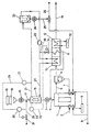
- In der Zeichnung ist mit 1 ein ein vorgewarmtes Koksbett enthaltender Thermoreaktor bezeichnet, welchem über eine Leitung 2 Abgase einer vorgeschalteten und nicht naher dargestellten Pyrolyseanlage bzw. eines Einschmelzreaktors zugeführt werden. Das beispielsweise bei der Pyrolyse von Müll in einem vorgeschalteten Verfahren entstandene CO- und H2-haltige Abgas wird vor dem Einbringen in den Thermoreaktor im wesentlichen lediglich einer Staubabscheidung, beispielsweise in einem Heißgaszyklon unterworfen. Das im Thermoreaktor 1 befindliche Koksbett wird über einen nachfolgend naher beschriebenen Inertgaskreislauf auf eine Temperatur von etwa 730°C vorgewärmt und über eine Zellradschleuse 3 bei 4 in den Thermoreaktor 1 eingebracht. Dem Koks sind, wie dies ebenfalls nachfolgend näher ausgeführt werden wird, Kalk und gegebenenfalls weitere Additive zu Erzielung einer verringerten Schlackenschmelztemperatur zugesetzt.
- Das durch das Koksbett im Thermoreaktor hindurchströmende und über die Leitung 2 zugeführte, brennbare Gas wird in einem unterstöchiometrischen C-fix-Vergasungsprozeß weiter mit Kohlenmonoxid und Wasserstoff zur Erhöhung seines Heizwertes angereichert, wobei im Koksbettreaktor in erster Linie nachstehend angeführte chemische Reaktionen ablaufen.
C + CO2 = 2CO (Boudouard)
C + 2H2 = CH4 (Methanisierung)
C + H2O = CO+H2 (heterogene Wassergasreaktion)
2C + O2 = 2CO
CO + H2O = CO2+H2 (homogene Wassergasreaktion)
CH4 + H2O = CO+3H2 (Methanspaltung)
bzw.
CxHy + H2O = xCO + (x + y)H2 (CxHy-Spaltung).
- Das im Thermoreaktor 1 gereinigte und durch Anreicherung mit CO und H2 einen erhöhten Heizwert aufweisende, brennbare Gas wird bei 5 aus dem Thermoreaktor 1 abgezogen und einem Heißzyklon 6 zugeführt, wobei der im Heißzyklon 6 abgeschiedene Staub über 7 in den Thermoreaktor wiederum rückgeführt wird.
- Die im Koks enthaltene Asche sowie die zugegebenen Schlackenbildner und der vom Staubfilter des Stickstoffkreislaufes zugeführte Staub werden in der unteren Zone des Koksbettreaktors 1, in der aufgrund einer mit 8 angedeuteten Sauerstoffzufuhr die notwendige Temperatur zum Schmelzen erreicht wird, aufgeschmolzen. Um die Schmelztemperatur herabzusetzen, wird entsprechend der Asche- und Staubanalyse dem Koks Kalkstein zugesetzt, sodaß die Zusammensetzung des Vierstoffsystems CaO, SiO2, Al2O3 und MgO im Bereich des möglichst niedrigsten Schmelzpunktes liegt. Durch die Zugabe von Kalkstein findet auch eine Entschwefelung des Abgases statt. Der vom Prozeßgas abgeschiedene Schwefel wird in der Schlacke 9 gebunden. Die entstehende Schlacke verläßt den Koksbettreaktor, wird abgeschreckt und granuliert.
- Das bei Temperaturen von etwa 1000°C mit CO und H2 angereicherte, brennbare Gas bzw. Exportgas gelangt nach Passieren des Heißgaszyklons 6 in einen Wärmetauscher 10, in welchem im brennbaren Gas enthaltene fühlbare Wärmeenergie zum Teil auf das zur Erwärmung des Kokses verwendete Inertgas übertragen wird. Nach dem Wärmetauscher 10 tritt das brennbare Gas durch einen weiteren Wärmetauscher 11 sowie durch einen Abhitzekessel 12 hindurch, wobei im Abhitzekessel eine Absenkung der Temperatur auf etwa 250°C unter Erzeugung von Dampf 13 erfolgt. Das brennbare Gas wird über eine Leitung 14 ausgeschleust und einer Reinigungsanlage bzw. einer weiteren Verwendung zugeführt.
- Zur Vorwärmung des über die Leitung 4 dem Thermoreaktor 1 zugeführten Kokses findet ein Vorwarmschacht 15 Verwendung, welcher von unten nach oben von einem inerten Gas, wie beispielsweise Stickstoff, durchströmt wird. Dem Vorwarmschacht wird über eine Zellradschleuse 16 über die Leitung 17 Koks 18 sowie die oben erwahnte Zusatzstoffe 19, wie insbesondere Kalk, zugeführt. Das zur Vorwarmung des Kokses dienende Inertgas tritt bei 20 in den Vorwarmschacht 15 ein und verlaßt diesen über eine Leitung 21, gelangt in ein Staubfilter 22 und tritt nach einer Verdichtung in einem Verdichter 23 durch den Wärmetauscher 10 hindurch, in welchem im Gegenstrom zum aus dem Heißgaszyklon 6 ausgebrachten brennbaren Gas eine Aufwärmung des Inertgases auf eine Temperatur von etwa 750°C erfolgt, so daß der Koks im Vorwarmschacht 15 unmittelbar vor Eintritt in den Thermoreaktor 1 eine Temperatur von etwa 730°C aufweist.
- Das Staubfilter 22 dient zur Abscheidung der Festkörper, die bei einer Durchströmung der Koksschicht im Vorwarmschacht 15 von der Gasphase mitgenommen werden, wobei mit einer Verstaubung von etwa 2 % des Kokseinsatzes gerechnet werden kann. Der aus dem Staubfilter 22 über eine Schleuse 24 bei 25 abgezogene Staub bzw. Feststoff wird gemeinsam mit über eine Leitung 26 zugeführter Luft bzw. Stickstoff in den Thermoreaktor 1 rückgeführt.
- Die CO-Konzentration im Inertgaskreislauf bzw. Stickstoffkreislauf wird laufend überwacht, wie dies durch das Meßgerät bzw. den Sensor 27 angedeutet ist. Bei einer Erhöhung des CO-Gehaltes über einen vorab festgelegten Grenzwert wird durch Zufuhr von frischem Inertgas, wie beispielsweise Stickstoff, über die Leitung 28 die CO-Konzentration herabgesetzt. In diesem Zusammenhang sind Steuerleitungen 29, ein Steuergerät 30 sowie eine entsprechende Ventilschaltung 31 angedeutet. Um bei Zufuhr von Stickstoff eine übermäßige Druckerhöhung im Inertgaskreislauf zu verhindern, wird über ein Steuergerät 32 und Steuerleitungen 33 ein Ventil 34 betätigt, so daß über eine Zweigleitung 35 nach dem Gebläse 23 ein entsprechender Teilstrom des im Inertgaskreislauf befindlichen Gases nach Passieren des Wärmetauschers 11 unmittelbar in den Thermoreaktor 1 eingespeist wird, so daß der Druck im Inertgaskreislauf zum Vorwärmen des in den Thermoreaktor 1 einzubringenden Kokses konstant gehalten wird.
Claims (7)
- Verfahren zur Herstellung und Reinigung brennbarer Gase aus Abgasen einer Pyrolyseanlage oder eines Einschmelzreaktors, bei welchem das Abgas über ein Koksbett (18) geführt wird, dadurch gekennzeichnet, daß der dem Koksbett zugeführte Koks (18) auf Temperaturen von > 600°C mit einem erhitzten Inertgas vorgewärmt wird.
- Verfahren nach Anspruch 1, dadurch gekennzeichnet, daß der erhitzte Koks (18) durch Zusatz von Kalk und gegebenenfalls weiteren Additiven (19) auf eine verringerte Schlackenschmelztemperatur eingestellt wird.
- Verfahren nach Anspruch 1 oder 2, dadurch gekennzeichnet, daß die Vorwärmung des Kokses (18) durch im Kreislauf geführtes Inertgas erfolgt, wobei das Inertgas durch das heiße, den Koksbettreaktor verlassende Exportgas auf Temperaturen von über 650°C, insbesondere etwa 730°C in einem Wärmetauscher erwärmt wird.
- Verfahren nach Anspruch 1, 2 oder 3, dadurch gekennzeichnet, daß der CO-Gehalt des im Kreislauf geführten Inertgases überwacht wird und bei Überschreiten eines Grenzwertes Inertgas, insbesondere N2, zugesetzt wird.
- Verfahren nach einem der Ansprüche 1 bis 4, dadurch gekennzeichnet, daß dem Koks Kalk in einer für die Entschwefelung des Exportgases ausreichenden Menge zugesetzt wird.
- Verfahren nach einem der Ansprüche 1 bis 5, dadurch gekennzeichnet, daß das Exportgas über einen Heißgaszyklon (6) geführt wird und daß der abgeschiedene Staub in den Reaktor (1) rückgeführt wird.
- Verfahren nach einem der Ansprüche 1 bis 6, dadurch gekennzeichnet, daß der aus dem Vorwarmschacht (15) des Kokses ausgetragene Staub zu wenigstens 50 Gew.-%, vorzugsweise etwa 70 Gew.-%, abgeschieden und in den Koksbettreaktor (1) rückgeführt wird.
Applications Claiming Priority (3)
| Application Number | Priority Date | Filing Date | Title |
|---|---|---|---|
| AT2061/92 | 1992-10-19 | ||
| AT206192A AT399509B (de) | 1992-10-19 | 1992-10-19 | Verfahren zur herstellung und reinigung brennbarer gase |
| PCT/AT1993/000157 WO1994009087A1 (de) | 1992-10-19 | 1993-10-19 | Verfahren zur herstellung und reinigung brennbarer gase |
Publications (2)
| Publication Number | Publication Date |
|---|---|
| EP0620840A1 EP0620840A1 (de) | 1994-10-26 |
| EP0620840B1 true EP0620840B1 (de) | 1997-01-22 |
Family
ID=3526949
Family Applications (1)
| Application Number | Title | Priority Date | Filing Date |
|---|---|---|---|
| EP93924421A Expired - Lifetime EP0620840B1 (de) | 1992-10-19 | 1993-10-19 | Verfahren zur herstellung und reinigung brennbarer gase |
Country Status (5)
| Country | Link |
|---|---|
| EP (1) | EP0620840B1 (de) |
| JP (1) | JP2701984B2 (de) |
| AT (1) | AT399509B (de) |
| DE (1) | DE59305263D1 (de) |
| WO (1) | WO1994009087A1 (de) |
Family Cites Families (3)
| Publication number | Priority date | Publication date | Assignee | Title |
|---|---|---|---|---|
| DE2935669C2 (de) * | 1979-09-04 | 1986-10-30 | Herko Pyrolyse Gmbh & Co Recycling Kg, 6832 Hockenheim | Widerstandsbeheizter Crackreaktor für die Abfallpyrolyse |
| DE3406307A1 (de) * | 1984-02-22 | 1985-08-22 | KPA Kiener Pyrolyse Gesellschaft für thermische Abfallverwertung mbH, 7000 Stuttgart | Verfahren zur erzeugung von brennbaren gasen aus abfallstoffe |
| DE3516419A1 (de) * | 1985-05-07 | 1986-11-13 | Jahn, Stephan, 8013 Haar | Verfahren und anlage zur reinigung von rauchgas |
-
1992
- 1992-10-19 AT AT206192A patent/AT399509B/de not_active IP Right Cessation
-
1993
- 1993-10-19 JP JP6509432A patent/JP2701984B2/ja not_active Expired - Fee Related
- 1993-10-19 EP EP93924421A patent/EP0620840B1/de not_active Expired - Lifetime
- 1993-10-19 DE DE59305263T patent/DE59305263D1/de not_active Expired - Fee Related
- 1993-10-19 WO PCT/AT1993/000157 patent/WO1994009087A1/de not_active Ceased
Also Published As
| Publication number | Publication date |
|---|---|
| JP2701984B2 (ja) | 1998-01-21 |
| JPH07502781A (ja) | 1995-03-23 |
| WO1994009087A1 (de) | 1994-04-28 |
| DE59305263D1 (de) | 1997-03-06 |
| EP0620840A1 (de) | 1994-10-26 |
| ATA206192A (de) | 1994-10-15 |
| AT399509B (de) | 1995-05-26 |
Similar Documents
| Publication | Publication Date | Title |
|---|---|---|
| AT507113B1 (de) | Verfahren und anlage zur energie- und co2-emissionsoptimierten eisenerzeugung | |
| DE3603054C2 (de) | Verfahren zur Vergasung von Klärschlamm | |
| EP0487856A2 (de) | Verfahren zur Herstellung von Roheisen bzw. Eisenschwamm | |
| AT405186B (de) | Anlage und verfahren zur herstellung von roheisen und/oder eisenschwamm | |
| AT406380B (de) | Verfahren zum herstellen von flüssigem roheisen oder flüssigen stahlvorprodukten sowie anlage zur durchführung des verfahrens | |
| EP3580312B1 (de) | Herstellung von synthesegas aus kohlenstoffreichen substanzen mittels eines kombiniertes gleichstrom-gegenstrom verfahrens | |
| DE2532197C3 (de) | Verfahren zur Erzeugung von Synthesegasen | |
| EP0072457A2 (de) | Verfahren und Vorrichtung zur Herstellung von Synthesegas | |
| AT405187B (de) | Verfahren zum herstellen von eisenschwamm sowie anlage zur durchführung des verfahrens | |
| EP4281524A1 (de) | Vorrichtung zum verwerten von prozessgas unter umsetzung von altstoffen und bildung von synthesegas | |
| DE3530240C2 (de) | Verfahren zum Schmelzen von zumindest teilweise reduziertem Eisenerz, sowie Vorrichtung zur Durchführung dieses Verfahrens | |
| EP3202922B1 (de) | Verfahren und anlage zur herstellung von eisenschwamm | |
| DE2508707A1 (de) | Verfahren zur schwelung von bituminoesem oder oelhaltigem material | |
| EP0870066B1 (de) | Verfahren zum aufarbeiten von müll sowie vorrichtung zur durchführung dieses verfahrens | |
| EP0809713B1 (de) | Verfahren zur herstellung von flüssigem roheisen oder flüssigen stahlvorprodukten und eisenschwamm sowie anlage zur durchführung des verfahrens | |
| EP0620840B1 (de) | Verfahren zur herstellung und reinigung brennbarer gase | |
| EP2148135B1 (de) | Verfahren und Vorrichtung zur thermischen Behandlung von Abfallgütern | |
| EP0617739B1 (de) | Verfahren zum kontinuierlichen einschmelzen von schrott | |
| AT401528B (de) | Verfahren zum erschmelzen von stahl aus schrott und/oder metallhaltigen, müllähnlichen stoffen | |
| DE2604140C3 (de) | Verfahren zur Herstellung von Synthese- und Reduktionsgas | |
| WO2014012651A1 (de) | Gegenstrom-/gleichstrom-vergasung von kohlenstoffreichen substanzen | |
| EP0511195B1 (de) | Verfahren zum kontinuierlichen Einschmelzen von Shredderschrott und Mischschrott | |
| AT528133B1 (de) | Verfahren zum Abtrennen von elementarem Phosphor aus Phosphat-haltigen Ausgangsstoffen | |
| AT397808B (de) | Verfahren zur druckvergasung von organischen substanzen, z.b. kunststoffmischungen | |
| DE69624819T2 (de) | Verfahren zur direkten gewinning von eisen und stahl |
Legal Events
| Date | Code | Title | Description |
|---|---|---|---|
| PUAI | Public reference made under article 153(3) epc to a published international application that has entered the european phase |
Free format text: ORIGINAL CODE: 0009012 |
|
| 17P | Request for examination filed |
Effective date: 19940616 |
|
| AK | Designated contracting states |
Kind code of ref document: A1 Designated state(s): BE CH DE DK ES FR GB GR IE IT LI LU MC NL PT SE |
|
| RAP1 | Party data changed (applicant data changed or rights of an application transferred) |
Owner name: MERCEDES-BENZ AG Owner name: VOEST-ALPINE INDUSTRIEANLAGENBAU GMBH |
|
| GRAG | Despatch of communication of intention to grant |
Free format text: ORIGINAL CODE: EPIDOS AGRA |
|
| 17Q | First examination report despatched |
Effective date: 19960320 |
|
| GRAH | Despatch of communication of intention to grant a patent |
Free format text: ORIGINAL CODE: EPIDOS IGRA |
|
| GRAH | Despatch of communication of intention to grant a patent |
Free format text: ORIGINAL CODE: EPIDOS IGRA |
|
| GRAA | (expected) grant |
Free format text: ORIGINAL CODE: 0009210 |
|
| AK | Designated contracting states |
Kind code of ref document: B1 Designated state(s): BE CH DE DK ES FR GB GR IE IT LI LU MC NL PT SE |
|
| PG25 | Lapsed in a contracting state [announced via postgrant information from national office to epo] |
Ref country code: NL Free format text: LAPSE BECAUSE OF FAILURE TO SUBMIT A TRANSLATION OF THE DESCRIPTION OR TO PAY THE FEE WITHIN THE PRESCRIBED TIME-LIMIT Effective date: 19970122 Ref country code: GR Free format text: LAPSE BECAUSE OF FAILURE TO SUBMIT A TRANSLATION OF THE DESCRIPTION OR TO PAY THE FEE WITHIN THE PRESCRIBED TIME-LIMIT Effective date: 19970122 Ref country code: ES Free format text: THE PATENT HAS BEEN ANNULLED BY A DECISION OF A NATIONAL AUTHORITY Effective date: 19970122 Ref country code: DK Effective date: 19970122 |
|
| REG | Reference to a national code |
Ref country code: CH Ref legal event code: EP |
|
| REF | Corresponds to: |
Ref document number: 59305263 Country of ref document: DE Date of ref document: 19970306 |
|
| REG | Reference to a national code |
Ref country code: IE Ref legal event code: FG4D Free format text: 71740 |
|
| ITF | It: translation for a ep patent filed | ||
| PG25 | Lapsed in a contracting state [announced via postgrant information from national office to epo] |
Ref country code: SE Effective date: 19970422 Ref country code: PT Effective date: 19970422 |
|
| GBT | Gb: translation of ep patent filed (gb section 77(6)(a)/1977) |
Effective date: 19970423 |
|
| ET | Fr: translation filed | ||
| NLV1 | Nl: lapsed or annulled due to failure to fulfill the requirements of art. 29p and 29m of the patents act | ||
| RAP2 | Party data changed (patent owner data changed or rights of a patent transferred) |
Owner name: DAIMLER-BENZ AKTIENGESELLSCHAFT Owner name: VOEST-ALPINE INDUSTRIEANLAGENBAU GMBH |
|
| PLBE | No opposition filed within time limit |
Free format text: ORIGINAL CODE: 0009261 |
|
| STAA | Information on the status of an ep patent application or granted ep patent |
Free format text: STATUS: NO OPPOSITION FILED WITHIN TIME LIMIT |
|
| PGFP | Annual fee paid to national office [announced via postgrant information from national office to epo] |
Ref country code: CH Payment date: 19971222 Year of fee payment: 5 Ref country code: MC Payment date: 19971222 Year of fee payment: 5 |
|
| 26N | No opposition filed | ||
| PG25 | Lapsed in a contracting state [announced via postgrant information from national office to epo] |
Ref country code: IE Free format text: LAPSE BECAUSE OF NON-PAYMENT OF DUE FEES Effective date: 19980330 |
|
| REG | Reference to a national code |
Ref country code: IE Ref legal event code: FD4D Ref document number: 71740 Country of ref document: IE |
|
| PG25 | Lapsed in a contracting state [announced via postgrant information from national office to epo] |
Ref country code: LI Free format text: LAPSE BECAUSE OF NON-PAYMENT OF DUE FEES Effective date: 19981031 Ref country code: CH Free format text: LAPSE BECAUSE OF NON-PAYMENT OF DUE FEES Effective date: 19981031 |
|
| PG25 | Lapsed in a contracting state [announced via postgrant information from national office to epo] |
Ref country code: MC Free format text: LAPSE BECAUSE OF NON-PAYMENT OF DUE FEES Effective date: 19990430 |
|
| REG | Reference to a national code |
Ref country code: CH Ref legal event code: PL |
|
| REG | Reference to a national code |
Ref country code: GB Ref legal event code: IF02 |
|
| PGFP | Annual fee paid to national office [announced via postgrant information from national office to epo] |
Ref country code: GB Payment date: 20030929 Year of fee payment: 11 |
|
| PGFP | Annual fee paid to national office [announced via postgrant information from national office to epo] |
Ref country code: LU Payment date: 20031001 Year of fee payment: 11 |
|
| PGFP | Annual fee paid to national office [announced via postgrant information from national office to epo] |
Ref country code: BE Payment date: 20031009 Year of fee payment: 11 Ref country code: FR Payment date: 20031009 Year of fee payment: 11 |
|
| PGFP | Annual fee paid to national office [announced via postgrant information from national office to epo] |
Ref country code: DE Payment date: 20031010 Year of fee payment: 11 |
|
| PG25 | Lapsed in a contracting state [announced via postgrant information from national office to epo] |
Ref country code: LU Free format text: LAPSE BECAUSE OF NON-PAYMENT OF DUE FEES Effective date: 20041019 Ref country code: GB Free format text: LAPSE BECAUSE OF NON-PAYMENT OF DUE FEES Effective date: 20041019 |
|
| PG25 | Lapsed in a contracting state [announced via postgrant information from national office to epo] |
Ref country code: BE Free format text: LAPSE BECAUSE OF NON-PAYMENT OF DUE FEES Effective date: 20041031 |
|
| BERE | Be: lapsed |
Owner name: *MERCEDES-BENZ A.G. Effective date: 20041031 Owner name: *VOEST-ALPINE INDUSTRIEANLAGENBAU G.M.B.H. Effective date: 20041031 |
|
| PG25 | Lapsed in a contracting state [announced via postgrant information from national office to epo] |
Ref country code: DE Free format text: LAPSE BECAUSE OF NON-PAYMENT OF DUE FEES Effective date: 20050503 |
|
| GBPC | Gb: european patent ceased through non-payment of renewal fee |
Effective date: 20041019 |
|
| PG25 | Lapsed in a contracting state [announced via postgrant information from national office to epo] |
Ref country code: FR Free format text: LAPSE BECAUSE OF NON-PAYMENT OF DUE FEES Effective date: 20050630 |
|
| REG | Reference to a national code |
Ref country code: FR Ref legal event code: ST |
|
| PG25 | Lapsed in a contracting state [announced via postgrant information from national office to epo] |
Ref country code: IT Free format text: LAPSE BECAUSE OF NON-PAYMENT OF DUE FEES;WARNING: LAPSES OF ITALIAN PATENTS WITH EFFECTIVE DATE BEFORE 2007 MAY HAVE OCCURRED AT ANY TIME BEFORE 2007. THE CORRECT EFFECTIVE DATE MAY BE DIFFERENT FROM THE ONE RECORDED. Effective date: 20051019 |
|
| BERE | Be: lapsed |
Owner name: *MERCEDES-BENZ A.G. Effective date: 20041031 Owner name: *VOEST-ALPINE INDUSTRIEANLAGENBAU G.M.B.H. Effective date: 20041031 |