EP0619986B1 - Longitudinal hin- und herbewegliches Einschneidegerät - Google Patents
Longitudinal hin- und herbewegliches Einschneidegerät Download PDFInfo
- Publication number
- EP0619986B1 EP0619986B1 EP93310267A EP93310267A EP0619986B1 EP 0619986 B1 EP0619986 B1 EP 0619986B1 EP 93310267 A EP93310267 A EP 93310267A EP 93310267 A EP93310267 A EP 93310267A EP 0619986 B1 EP0619986 B1 EP 0619986B1
- Authority
- EP
- European Patent Office
- Prior art keywords
- cutting
- shaft
- sheath
- cutting member
- distal end
- Prior art date
- Legal status (The legal status is an assumption and is not a legal conclusion. Google has not performed a legal analysis and makes no representation as to the accuracy of the status listed.)
- Expired - Lifetime
Links
- 210000004283 incisor Anatomy 0.000 title description 2
- 238000005520 cutting process Methods 0.000 claims description 98
- 230000002966 stenotic effect Effects 0.000 claims description 34
- 210000001367 artery Anatomy 0.000 claims description 29
- 238000003780 insertion Methods 0.000 claims description 19
- 230000037431 insertion Effects 0.000 claims description 19
- 239000012530 fluid Substances 0.000 claims description 6
- 239000011800 void material Substances 0.000 claims 2
- 208000031481 Pathologic Constriction Diseases 0.000 description 32
- 208000037804 stenosis Diseases 0.000 description 30
- 230000036262 stenosis Effects 0.000 description 29
- 238000000034 method Methods 0.000 description 22
- 238000002399 angioplasty Methods 0.000 description 20
- 230000010339 dilation Effects 0.000 description 13
- 238000001356 surgical procedure Methods 0.000 description 5
- 210000001519 tissue Anatomy 0.000 description 5
- 206010060965 Arterial stenosis Diseases 0.000 description 4
- 230000009471 action Effects 0.000 description 4
- 239000008280 blood Substances 0.000 description 3
- 210000004369 blood Anatomy 0.000 description 3
- 230000008602 contraction Effects 0.000 description 3
- 230000000916 dilatatory effect Effects 0.000 description 3
- 239000000835 fiber Substances 0.000 description 3
- 210000004204 blood vessel Anatomy 0.000 description 2
- 230000006835 compression Effects 0.000 description 2
- 238000007906 compression Methods 0.000 description 2
- 210000004351 coronary vessel Anatomy 0.000 description 2
- 210000001105 femoral artery Anatomy 0.000 description 2
- 238000004519 manufacturing process Methods 0.000 description 2
- 210000003205 muscle Anatomy 0.000 description 2
- 206010016654 Fibrosis Diseases 0.000 description 1
- 238000005452 bending Methods 0.000 description 1
- 230000017531 blood circulation Effects 0.000 description 1
- 230000036770 blood supply Effects 0.000 description 1
- 230000008859 change Effects 0.000 description 1
- 238000010276 construction Methods 0.000 description 1
- 230000003247 decreasing effect Effects 0.000 description 1
- 230000003292 diminished effect Effects 0.000 description 1
- 230000000694 effects Effects 0.000 description 1
- 230000004761 fibrosis Effects 0.000 description 1
- 230000003176 fibrotic effect Effects 0.000 description 1
- 230000036541 health Effects 0.000 description 1
- 238000012977 invasive surgical procedure Methods 0.000 description 1
- 239000000463 material Substances 0.000 description 1
- 239000000203 mixture Substances 0.000 description 1
- 208000010125 myocardial infarction Diseases 0.000 description 1
- 230000002980 postoperative effect Effects 0.000 description 1
- 238000011084 recovery Methods 0.000 description 1
- 230000009467 reduction Effects 0.000 description 1
- 239000007787 solid Substances 0.000 description 1
Images


Classifications
-
- A—HUMAN NECESSITIES
- A61—MEDICAL OR VETERINARY SCIENCE; HYGIENE
- A61B—DIAGNOSIS; SURGERY; IDENTIFICATION
- A61B17/00—Surgical instruments, devices or methods
- A61B17/32—Surgical cutting instruments
- A61B17/3205—Excision instruments
- A61B17/3207—Atherectomy devices working by cutting or abrading; Similar devices specially adapted for non-vascular obstructions
-
- A—HUMAN NECESSITIES
- A61—MEDICAL OR VETERINARY SCIENCE; HYGIENE
- A61B—DIAGNOSIS; SURGERY; IDENTIFICATION
- A61B17/00—Surgical instruments, devices or methods
- A61B17/32—Surgical cutting instruments
- A61B17/3209—Incision instruments
-
- A—HUMAN NECESSITIES
- A61—MEDICAL OR VETERINARY SCIENCE; HYGIENE
- A61B—DIAGNOSIS; SURGERY; IDENTIFICATION
- A61B18/00—Surgical instruments, devices or methods for transferring non-mechanical forms of energy to or from the body
-
- A—HUMAN NECESSITIES
- A61—MEDICAL OR VETERINARY SCIENCE; HYGIENE
- A61B—DIAGNOSIS; SURGERY; IDENTIFICATION
- A61B18/00—Surgical instruments, devices or methods for transferring non-mechanical forms of energy to or from the body
- A61B18/18—Surgical instruments, devices or methods for transferring non-mechanical forms of energy to or from the body by applying electromagnetic radiation, e.g. microwaves
- A61B18/20—Surgical instruments, devices or methods for transferring non-mechanical forms of energy to or from the body by applying electromagnetic radiation, e.g. microwaves using laser
- A61B18/22—Surgical instruments, devices or methods for transferring non-mechanical forms of energy to or from the body by applying electromagnetic radiation, e.g. microwaves using laser the beam being directed along or through a flexible conduit, e.g. an optical fibre; Couplings or hand-pieces therefor
- A61B18/24—Surgical instruments, devices or methods for transferring non-mechanical forms of energy to or from the body by applying electromagnetic radiation, e.g. microwaves using laser the beam being directed along or through a flexible conduit, e.g. an optical fibre; Couplings or hand-pieces therefor with a catheter
- A61B18/245—Surgical instruments, devices or methods for transferring non-mechanical forms of energy to or from the body by applying electromagnetic radiation, e.g. microwaves using laser the beam being directed along or through a flexible conduit, e.g. an optical fibre; Couplings or hand-pieces therefor with a catheter for removing obstructions in blood vessels or calculi
-
- A—HUMAN NECESSITIES
- A61—MEDICAL OR VETERINARY SCIENCE; HYGIENE
- A61B—DIAGNOSIS; SURGERY; IDENTIFICATION
- A61B17/00—Surgical instruments, devices or methods
- A61B17/22—Implements for squeezing-off ulcers or the like on inner organs of the body; Implements for scraping-out cavities of body organs, e.g. bones; for invasive removal or destruction of calculus using mechanical vibrations; for removing obstructions in blood vessels, not otherwise provided for
- A61B2017/22038—Implements for squeezing-off ulcers or the like on inner organs of the body; Implements for scraping-out cavities of body organs, e.g. bones; for invasive removal or destruction of calculus using mechanical vibrations; for removing obstructions in blood vessels, not otherwise provided for with a guide wire
-
- A—HUMAN NECESSITIES
- A61—MEDICAL OR VETERINARY SCIENCE; HYGIENE
- A61B—DIAGNOSIS; SURGERY; IDENTIFICATION
- A61B17/00—Surgical instruments, devices or methods
- A61B17/22—Implements for squeezing-off ulcers or the like on inner organs of the body; Implements for scraping-out cavities of body organs, e.g. bones; for invasive removal or destruction of calculus using mechanical vibrations; for removing obstructions in blood vessels, not otherwise provided for
- A61B2017/22051—Implements for squeezing-off ulcers or the like on inner organs of the body; Implements for scraping-out cavities of body organs, e.g. bones; for invasive removal or destruction of calculus using mechanical vibrations; for removing obstructions in blood vessels, not otherwise provided for with an inflatable part, e.g. balloon, for positioning, blocking, or immobilisation
- A61B2017/22062—Implements for squeezing-off ulcers or the like on inner organs of the body; Implements for scraping-out cavities of body organs, e.g. bones; for invasive removal or destruction of calculus using mechanical vibrations; for removing obstructions in blood vessels, not otherwise provided for with an inflatable part, e.g. balloon, for positioning, blocking, or immobilisation to be filled with liquid
-
- A—HUMAN NECESSITIES
- A61—MEDICAL OR VETERINARY SCIENCE; HYGIENE
- A61B—DIAGNOSIS; SURGERY; IDENTIFICATION
- A61B90/00—Instruments, implements or accessories specially adapted for surgery or diagnosis and not covered by any of the groups A61B1/00 - A61B50/00, e.g. for luxation treatment or for protecting wound edges
- A61B90/03—Automatic limiting or abutting means, e.g. for safety
-
- A—HUMAN NECESSITIES
- A61—MEDICAL OR VETERINARY SCIENCE; HYGIENE
- A61M—DEVICES FOR INTRODUCING MEDIA INTO, OR ONTO, THE BODY; DEVICES FOR TRANSDUCING BODY MEDIA OR FOR TAKING MEDIA FROM THE BODY; DEVICES FOR PRODUCING OR ENDING SLEEP OR STUPOR
- A61M25/00—Catheters; Hollow probes
- A61M25/10—Balloon catheters
- A61M25/104—Balloon catheters used for angioplasty
Definitions
- the present invention pertains generally to medical devices for reducing the flow restriction caused by a stenosis in an artery. More specifically, the present invention relates to devices for incising an arterial stenosis. The present invention is particularly, but not exclusively, useful for longitudinally incising an arterial stenosis prior to and in conjunction with angioplasty.
- bypass surgery is invasive, and can consequently require significant post-operative recovery time.
- less invasive surgical procedures have been developed wherein a device is inserted into the bloodstream of a patient and advanced into an artery to reduce or remove an arterial stenosis.
- angioplasty One well known and frequently used procedure to accomplish this task is popularly known as angioplasty.
- a dilating balloon is positioned across the particular stenotic segment and the balloon is inflated to open the artery by breaking up and compressing the plaque which is creating the stenosis.
- the plaque remains in the artery and is not removed.
- the plaque which remains in the artery may still present a stenosis.
- there is a re-stenosis. This high recurrence rate is thought to be the result of fibrotic contraction in the lumen of the vessel. In these situations, other more drastic procedures need to be employed.
- Atherectomy procedures have been developed to resolve the problems caused by blocked arteries.
- an atherectomy procedure mechanically cuts and removes the plaque which is creating the stenosis from the artery.
- Many examples of such cutting devices can be given.
- U.S. Patent No. 4,895,166 which issued to Farr et al. for an invention entitled “Rotatable Cutter for the Lumen of a Blood Vessel", and which is assigned to the same assignee as the present invention, discloses such a cutter.
- U.S. Patent No. 4,589,412 which issued to Kensey for an invention entitled “Method and Apparatus for Surgically Removing Remote Deposits” is but another example.
- the stenosis is therefore more likely to maintain a compressed configuration if the fibers are incised prior to balloon dilation.
- the completeness of the compression of the stenosis is dependant on whether the inflated balloon is able to break apart fibers in the tissue.
- dilation of a segment is of course limited by the arteries able to withstand dilation. Over-dilation can have the catastrophic result of rupturing the vessel.
- an object of the present invention to provide an improved device for longitudinally incising a stenotic segment of an artery prior to an angioplasty procedure. It is another object of the present invention to provide a cutting device which, in cooperation with an angioplasty procedure, is able to produce an opening in a stenotic segment where the diameter of the opening is greater than the insertion diameter of the device. It is yet another object of the present invention to provide a device insertable into an obstructed artery which incises a stenosis without producing potentially harmful cuttings. It is also an object of the present invention to provide a device which allows improved control over the length of the incisions produced in the stenotic segment.
- Yet another object of the present invention is to provide a device which is flexible enough to allow advancement of the device through narrow vessels and around sharp turns. Still further, it is an object of the present invention to provide a device for longitudinally incising a stenotic segment of an artery which is relatively easy to manufacture and is comparatively economical.
- the present invention is an insertable catheter device which longitudinally incises a stenotic segment of an artery prior to balloon dilation.
- the catheter device includes a hollow catheter sheath and a cutting member which is reciprocatably mounted in the catheter sheath.
- the cutting member includes a central hollow shaft having a lumen which is sized to be placed on a typical guide wire. Attached near the distal end of the shaft are one or more cutting units, such as cutting blades or cauteries, which extend radially from the shaft.
- the hollow catheter sheath is formed with an opening at its distal end which includes a circular center having a diameter sufficient to allow the guide wire and the hollow shaft of the cutting member to extend therethrough.
- the opening also includes one or more longitudinally aligned slots which extend radially from the circular center.
- the cutting member is normally enclosed in the catheter sheath and is reciprocatingly disposed therein to be selectively extended from the sheath as desired by the operator.
- the slots at the end of the catheter sheath are sized to allow the cutting units attached to the shaft to exit the sheath whenever the cutting member is moved distally relative to the sheath.
- the sheath can cover the cutting member during insertion and placement of the device (the insertion configuration)
- the cutting member can also be advanced relative to the sheath (the cutting configuration) to make incisions in the stenotic segment.
- the portion of the hollow shaft including the cutting units extends out of the distal end of the sheath allowing the cutting units to incise the stenosis.
- the distal end of the sheath is tapered to a rounded point. Moreover, the wall thickness of the sheath is increased near the distal end to prevent the distal end, from enlarging and splaying during insertion and placement of the device.
- lugs Attached to the hollow shaft of the cutting member, at a location proximal of the cutting units, are a plurality of lugs. These lugs are equally spaced about and radially extend from the hollow shaft. Additionally, the lugs radially extend a sufficient distance to cooperatively engage longitudinal slots which are formed in the inside wall of the catheter sheath. The engagement between the lugs and the longitudinal slots allows the shaft to reciprocate a predetermined distance while preventing rotation of the shaft relative to the sheath. In this manner the longitudinal slots in the catheter sheath determine the maximum length of the incisions in the stenotic segment while maintaining the alignment of the cutting member relative to the sheath.
- the device of the present invention can be used and removed prior to a standard angioplasty procedure, it is likewise possible for the device to include an inflatable balloon along the hollow shaft between the cutting member and the lugs. The device can then be used to create the longitudinal incisions in the stenotic segment as well as perform the angioplasty procedure.
- the shaft of the cutting member is typically relatively rigid.
- the shaft can include a flexible portion.
- a standard guide wire is placed into the arterial system of a patient and passed through the stenotic segment.
- the device of the present invention is placed on the guide wire and then advanced through the arterial system, along the guide wire, until it is located adjacent the stenosis.
- the surgeon passes the cutting units through the stenotic segment by advancing the hollow shaft relative to the catheter sheath thereby incising the stenosis. Having passed the cutting units through the segment, the shaft is then retracted relative to the sheath. It is possible that multiple passes will be desirable to produce a greater number of incisions. If this is the case, the sheath, and therefore the cutting member, can be rotated slightly between successive passes through the stenotic segment.
- the shaft can be advanced an amount sufficient to place the inflatable balloon in the stenotic segment.
- the balloon can then be inflated and deflated to compress the stenotic tissue and expand the opening through the stenosis.
- the device can be removed from the arterial system and a standard angioplasty procedure can be performed on the incised stenosis.
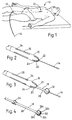
- the longitudinal cutting device of the present invention is shown and generally designated 10.
- Device 10 is shown inserted into the arterial system of a man 12 in the customary manner.
- device 10 is inserted through an insertion catheter 13 into the femoral artery and advanced through the arterial system to the stenotic segment.
- FIGS. 2 and 3 device 10 is shown on a standard guide wire 14.
- the device 10 includes a catheter sheath 16 and a cutting member 18.
- FIG. 2 shows the insertion configuration of device 10 wherein the cutting member 18 is retracted into the catheter sheath 16.
- FIG. 3 shows the extended or cutting configuration of device 10 wherein the cutting member 18 extends from the distal end 20 of the catheter sheath 16.
- Catheter sheath 16 is formed with an opening 22 at its distal end which allows both the guide wire 14 and the cutting member 18 to exit. Opening 22 includes radial slots 24 extending from a substantially circular center portion.
- the hollow interior of sheath 16 and opening 22 are formed to provide a means for receiving and enclosing the cutting member 18.
- Catheter sheath 16 also forms longitudinal slots 26 located more proximally along the body portion of the sheath.
- the cutting member 18 is shown and including a hollow shaft 28 defining a lumen 30.
- Lumen 30 is of sufficient size to accommodate a standard guide wire and to act as a fluid conduit for dilating an angioplastic balloon. Dilation fluid is prevented from exiting the end of hollow shaft 28 by a seal (not shown) in the lumen of the shaft.
- shaft 28 may be solid if a guide wire is not required.
- Cutting blades 32 are attached to shaft 28 at its distal end and extend radially from and are symmetrical about shaft 28. While four blades 32a-d are shown, it is to be appreciated that one or more blades could be used. Moreover, as can be appreciated by those skilled in the art, cutting blades 32 could be replaced by cauteries or lasers. The number of radial slots 24 in distal end 20 corresponds to the number of blades or cauteries.
- Alignment lugs 34 are also attached to shaft 28, although at a location more proximal than the cutting blades 32. While four, radial, symmetrically spaced lugs 34 are shown, one or more lugs could be used without departing from the scope of the present invention.
- Device 10 is shown installed on a guide wire 14 and in an artery 36 adjacent a stenosis 38.
- device 10 is in the insertion configuration where cutting member 18 is retracted into the radial slots 24 of catheter sheath 16.
- Alignment lugs 34 slidingly engage longitudinal slots 26. The cooperative engagement between the lugs 34 and the longitudinal slots 26 allows cutting member 18 to move longitudinally a predetermined distance, but prevents cutting member 18 from rotating relative to the sheath 16.
- longitudinal slots 26 are shown as extending from the inside wall of sheath 16 to the outside of sheath 16, it is possible to use slots not completely passing through the sheath wall without departing from the scope of the present invention. It is to be appreciated that by having slots 26 completely pass through the wall of sheath 16, the blood flow restriction caused by the instrument is reduced. Said differently, by including through slots 26, blood can flow through the slots 26, the sheath 16 and radial slots 24 to reduce the flow restriction caused by the instrument itself.
- FIG. 6 shows device 10 in the extended or cutting configuration where cutting member 18 is extending from the catheter sheath 16. Alignment lugs 34 remain in the longitudinal slots 26 at all times during the reciprocating movement of the cutting member 18 relative to the catheter sheath 16.
- the distal end 20 of catheter sheath 16 is tapered to a rounded point 45 to facilitate insertion and placement of the device 10.
- the catheter sheath wall thickness at distal end 20 is increased to prevent the end from enlarging or splaying during insertion and placement of device 10.
- an alternative embodiment of the present invention is shown and generally designated 40.
- This embodiment has a catheter sheath 16, a cutting member 18 having cutting blades 32 and alignment lugs 34, as well as longitudinal slots 26 and radial slots 24.
- device 40 includes an inflatable dilation balloon 42 attached to the cutting member 18 between the cutting blades 32 and the alignment lugs 34.
- the dilation balloon 42 is well known and as those skilled in the art will appreciate, the location of balloon 42 in device 40 can be varied to accommodate the procedure for which it is to be used. For example, in some situations it may be desirable to place the dilation balloon distally of the cutting blades 32.
- the interior 46 of the dilation balloon 42 is connected to a balloon inflation means via the lumen 30 and fluid opening 48 as is well known in the art.
- Device 50 is substantially the same as device 10 except that shaft 28 includes a flexible member 52.
- flexible member 52 can be a coiled spring, such as is used in a flexible guide wire, as well as any other material allowing localized bending of shaft 28. Additional flexible members could be added along shaft 28 to provide additional flexibility.
- One of the reasons for including the flexible member 52 is to permit shaft 28 to follow the path of the flexible guide wire 14 through the curves and branches of the coronary artery tree.
- Inclusion of one or more flexible members 52 allows device 50 to be used in situations where the stenotic segment is located at or near a bend in the vessel. In those situations, it may be necessary for the incisions to be made along an axis noncolinear with the longitudinal axis of device 50. Flexible member 52 allows the necessary flexibility to achieve this noncolinear incising.
- Device 60 is substantially the same as device 40 except that shaft 28 includes a flexible member 62. While Figure 9 shows a flexible member on either side of fluid opening 48, it is to be appreciated that a single flexible member 62 on only one side of fluid opening 48 would not depart from the scope of the present invention.
- Flexible member 62 allows shaft 28 to flex when it is desirable to have incisions noncolinear with the longitudinal axis of device 60. As those skilled in the art will appreciate, it may be desirable to provide additional flexible members 62 to provide additional flexibility. Additional flexible members 62 can be located within the balloon or outside the balloon along shaft 28.
- device 10 is typically inserted into the arterial system through an insertion catheter 13 previously inserted into the femoral artery as shown in FIG. 1.
- device 10 is in the insertion configuration as is depicted in FIGS. 2 and 5 where the cutting member 18 is retracted into catheter sheath 16.
- Device 10 is advanced into the artery 36 having a stenotic segment and is positioned adjacent the stenosis 38 as is well known in the art. Once adjacent the stenotic segment, cutting member 18 is advanced distally while the catheter sheath 16 is held stationary. In this manner, cutting blades 32 exit catheter sheath 16 and make incisions 44 in stenosis 38 as shown in FIG. 6.
- the cutting action of the device is increased by the contractions of the heart itself.
- the muscles adjacent the stenotic segment of the artery contract, the stenosis is forced against the cutting surfaces of the instrument.
- the muscle relaxes the stenosis can move away from the cutters.
- the contractions and relaxations provide a chopping or sawing action which in turn increases the effectiveness of the cutters.
- Another way to increase the cutting action of the device is to manually or mechanically move the shaft 28, and therefore the cutters, in a "to-and-fro" motion as the blades 32 are passed through the stenotic segment. This sawing action, as noted above, results in increased cutting efficiencies. After making incisions 44, cutting member 18 can be retracted.
- a single incisional pass through the stenotic segment may be sufficient, although typically it will be preferable to increase the number of incisions using multiple passes.
- the catheter sheath 16 is rotated slightly between passes through the stenosis 38. Rotating the sheath 16 rotates cutting blades 32 because the cutting member 18 is held in rotational alignment with sheath 16 by the cooperation between lugs 34 and longitudinal slots 26.
- Surgical control over the length of the incisions is also provided by the device of the present invention.
- the maximum length of an incision is determined by the length of the longitudinal slots 26.
- Dilation can be accomplished by positioning and inflating an inflatable balloon connected to the device of the present invention as is shown in FIG. 7.
- device 10 can be removed from the arterial system and a routine angioplasty procedure can be performed using the same guide wire.
- the catheter can be advanced after the incisions have been made. In this manner, the catheter acts as a dilator. Accordingly, by alternatingly incising and advancing the catheter, very long stenoses can be treated. Because the distal end of the catheter is rounded, dilation using the catheter is possible with minimal risk of damaging the artery. The risk of arterial damage would be significantly greater using a standard catheter which did not include a rounded distal end.
Landscapes
- Health & Medical Sciences (AREA)
- Surgery (AREA)
- Life Sciences & Earth Sciences (AREA)
- Medical Informatics (AREA)
- Nuclear Medicine, Radiotherapy & Molecular Imaging (AREA)
- Engineering & Computer Science (AREA)
- Biomedical Technology (AREA)
- Heart & Thoracic Surgery (AREA)
- Vascular Medicine (AREA)
- Molecular Biology (AREA)
- Animal Behavior & Ethology (AREA)
- General Health & Medical Sciences (AREA)
- Public Health (AREA)
- Veterinary Medicine (AREA)
- Media Introduction/Drainage Providing Device (AREA)
- Surgical Instruments (AREA)
Claims (11)
- In eine Arterie einführbare Vorrichtung (10) zum Schneiden von stenotischem Gewebe (38), umfassend:eine Katheterhülle (16) mit einem Körperabschnitt, einem proximalen Ende und einem distalen Ende (20), welche Hülle (16) eine Längsachse und ein inneres Aufnahmemittel (22, 24) am distalen Ende (20) festlegt, wobei der Körperabschnitt eine Innenfläche und eine Außenfläche aufweist,ein Schneidelement (18) zum Einschneiden in Gewebe, umfassend einen ein Schneidmittel (32) tragenden Schaft (28), wobei das Schneidelement (18) längs der Längsachse hin- und hergehend bewegbar ist und das Schneidelement (18) in einer zurückgezogenen Stellung vollständig innerhalb des Aufnahmemittels (22, 24) angeordnet ist und in einer vorgeschobenen Stellung teilweise aus dem Aufnahmemittel (22, 24) herausragt, welche Vorrichtung dadurch gekennzeichnet ist, daß sie ferner ein in der Katheterhülle (16) enthaltenes Begrenzungsmittel (26) zum Begrenzen und Ausrichten der Hin- und Herbewegungen des Schneidelements (18) aufweist, wobei das Begrenzungsmittel (26) am Schneidelement (18) angreift.
- Vorrichtung (10) nach Anspruch 1, wobei das Aufnahmemittel (22, 24) das Schneidmittel (32) an einer Berührung des Gewebes (38) hindert, wenn sich das Schneidelement (18) in der zurückgezogenen Stellung befindet.
- Vorrichtung (10) nach Anspruch 2, wobei das Aufnahmemittel (22, 24) einen durch die Innenfläche festgelegten inneren, koaxialen Hohlraum und eine durch das distale Ende (20) der Hülle (16) gebildete Öffnung (22, 24) aufweist, welche Öffnung geformt und bemessen ist, um das Schneidmittel (32) aus dem koaxialen Hohlraum austreten zu lassen.
- Vorrichtung (10) nach einem der vorangehenden Ansprüche, ferner umfassend eine Anzahl von Ausrichtlappen (34), die nahe (proximally) dem Schneidmittel (32) radial vom Schaft (28) abstehen und daran angebracht sind, welche Ausrichtlappen (34) gleitend oder verschiebbar am Begrenzungsmittel (26) angreifen, um die Hin- und Herbewegungen des Schneidelements (18) zu begrenzen und auszurichten, und wobei der Schaft (28) hohl ist.
- Vorrichtung (10) nach Anspruch 4, wobei das Begrenzungsmittel (26) aus einer Anzahl von durch die Innenfläche der Hülle (16) geformten Längsschlitzen (26) besteht.
- Vorrichtung (10) nach einem der vorangehenden Ansprüche, wobei das Schneidmittel (32) mindestens eine Schneidklinge (32) umfaßt, die am Schaft (28) angebracht ist und radial von ihm absteht.
- Vorrichtung (10) nach einem der Ansprüche 1 bis 5, wobei das Schneidmittel (32) eine Anzahl von Schneidklingen (32) umfaßt, die am Schaft (28) angebracht sind und radial von ihm abstehen, welche Klingen (32) um den Schaft (28) herum im wesentlichen gleich weit beabstandet sind.
- Vorrichtung (40) nach Anspruch 5, wobei das Schneidmittel (32) mindestens einen am Schaft (28) angebrachten und radial von ihm abstehenden Kauter (cautery) umfaßt.
- Vorrichtung (10) nach einem der vorangehenden Ansprüche, ferner umfassend einen am Schaft (28) montierten aufblasbaren Ballon (42), der in Fluidverbindung mit einem Ballonaufblasmittel steht.
- Vorrichtung (10) nach Anspruch 5, wobei die Hülle (16) eine Wanddicke aufweist, die sich am distalen Ende (20) vergrößert, um eine Deformation und ein Spreizen des distalen Endes (20) beim Einführen und Plazieren der Vorrichtung (10) zu verhindern.
- Vorrichtung (10, 40, 50, 60) nach einem der vorangehenden Ansprüche, wobei der Schaft (28) mindestens ein flexibles Element (52, 82) zur Ermöglichung einer Durchbiegung des Schafts (28) aufweist.
Applications Claiming Priority (2)
| Application Number | Priority Date | Filing Date | Title |
|---|---|---|---|
| US39881 | 1979-05-18 | ||
| US08/039,881 US5372601A (en) | 1993-03-30 | 1993-03-30 | Longitudinal reciprocating incisor |
Publications (2)
| Publication Number | Publication Date |
|---|---|
| EP0619986A1 EP0619986A1 (de) | 1994-10-19 |
| EP0619986B1 true EP0619986B1 (de) | 1997-05-07 |
Family
ID=21907834
Family Applications (1)
| Application Number | Title | Priority Date | Filing Date |
|---|---|---|---|
| EP93310267A Expired - Lifetime EP0619986B1 (de) | 1993-03-30 | 1993-12-17 | Longitudinal hin- und herbewegliches Einschneidegerät |
Country Status (5)
| Country | Link |
|---|---|
| US (1) | US5372601A (de) |
| EP (1) | EP0619986B1 (de) |
| JP (1) | JPH07409A (de) |
| CA (1) | CA2115468C (de) |
| DE (1) | DE69310498T2 (de) |
Families Citing this family (156)
| Publication number | Priority date | Publication date | Assignee | Title |
|---|---|---|---|---|
| CA2157697C (en) * | 1995-01-10 | 2007-03-13 | Banning Gray Lary | Vascular incisor/dilator |
| US5556405A (en) * | 1995-10-13 | 1996-09-17 | Interventional Technologies Inc. | Universal dilator with reciprocal incisor |
| US5817013A (en) * | 1996-03-19 | 1998-10-06 | Enable Medical Corporation | Method and apparatus for the minimally invasive harvesting of a saphenous vein and the like |
| CA2209366C (en) * | 1996-09-13 | 2004-11-02 | Interventional Technologies, Inc. | Incisor-dilator with tapered balloon |
| US5713913A (en) * | 1996-11-12 | 1998-02-03 | Interventional Technologies Inc. | Device and method for transecting a coronary artery |
| US6019771A (en) * | 1996-12-02 | 2000-02-01 | Cardiothoracic Systems, Inc. | Devices and methods for minimally invasive harvesting of a vessel especially the saphenous vein for coronary bypass grafting |
| US5938680A (en) * | 1997-06-19 | 1999-08-17 | Cardiothoracic Systems, Inc. | Devices and methods for harvesting vascular conduits |
| US6090118A (en) | 1998-07-23 | 2000-07-18 | Mcguckin, Jr.; James F. | Rotational thrombectomy apparatus and method with standing wave |
| US9586023B2 (en) | 1998-02-06 | 2017-03-07 | Boston Scientific Limited | Direct stream hydrodynamic catheter system |
| WO2009117663A2 (en) | 2008-03-20 | 2009-09-24 | Medrad, Inc. | Direct stream hydrodynamic catheter system |
| US7879022B2 (en) | 1998-02-06 | 2011-02-01 | Medrad, Inc. | Rapid exchange fluid jet thrombectomy device and method |
| US5989210A (en) * | 1998-02-06 | 1999-11-23 | Possis Medical, Inc. | Rheolytic thrombectomy catheter and method of using same |
| US6666874B2 (en) | 1998-04-10 | 2003-12-23 | Endicor Medical, Inc. | Rotational atherectomy system with serrated cutting tip |
| US6001112A (en) | 1998-04-10 | 1999-12-14 | Endicor Medical, Inc. | Rotational atherectomy device |
| US6482217B1 (en) | 1998-04-10 | 2002-11-19 | Endicor Medical, Inc. | Neuro thrombectomy catheter |
| US8328829B2 (en) | 1999-08-19 | 2012-12-11 | Covidien Lp | High capacity debulking catheter with razor edge cutting window |
| US7713279B2 (en) | 2000-12-20 | 2010-05-11 | Fox Hollow Technologies, Inc. | Method and devices for cutting tissue |
| US7708749B2 (en) | 2000-12-20 | 2010-05-04 | Fox Hollow Technologies, Inc. | Debulking catheters and methods |
| US7887556B2 (en) | 2000-12-20 | 2011-02-15 | Fox Hollow Technologies, Inc. | Debulking catheters and methods |
| US6299622B1 (en) | 1999-08-19 | 2001-10-09 | Fox Hollow Technologies, Inc. | Atherectomy catheter with aligned imager |
| AU2614901A (en) | 1999-10-22 | 2001-04-30 | Boston Scientific Corporation | Double balloon thrombectomy catheter |
| US8414543B2 (en) | 1999-10-22 | 2013-04-09 | Rex Medical, L.P. | Rotational thrombectomy wire with blocking device |
| FR2800984B1 (fr) * | 1999-11-17 | 2001-12-14 | Jacques Seguin | Dispositif de remplacement d'une valve cardiaque par voie percutanee |
| AU2002231074A1 (en) | 2000-12-20 | 2002-07-01 | Fox Hollow Technologies, Inc. | Debulking catheter |
| US6616676B2 (en) * | 2001-04-10 | 2003-09-09 | Scimed Life Systems, Inc. | Devices and methods for removing occlusions in vessels |
| JP2002358378A (ja) * | 2001-06-01 | 2002-12-13 | Fujitsu Ltd | 店舗管理システム |
| US6632231B2 (en) * | 2001-08-23 | 2003-10-14 | Scimed Life Systems, Inc. | Segmented balloon catheter blade |
| US6951566B2 (en) * | 2002-01-25 | 2005-10-04 | Scimed Life Systems, Inc. | Reciprocating cutting and dilating balloon |
| US7985234B2 (en) * | 2002-02-27 | 2011-07-26 | Boston Scientific Scimed, Inc. | Medical device |
| US7329267B2 (en) * | 2002-12-23 | 2008-02-12 | Boston Scientific Scimed, Inc. | Medical cutting devices and methods of use |
| US7285109B2 (en) * | 2003-02-13 | 2007-10-23 | Boston Scientific Scimed, Inc. | Device and method for collapsing an angioplasty balloon |
| JP2004297166A (ja) * | 2003-03-25 | 2004-10-21 | Murata Mfg Co Ltd | 温度補償型圧電発振器およびそれを用いた電子装置 |
| US8246640B2 (en) | 2003-04-22 | 2012-08-21 | Tyco Healthcare Group Lp | Methods and devices for cutting tissue at a vascular location |
| US7279002B2 (en) * | 2003-04-25 | 2007-10-09 | Boston Scientific Scimed, Inc. | Cutting stent and balloon |
| US7632288B2 (en) | 2003-05-12 | 2009-12-15 | Boston Scientific Scimed, Inc. | Cutting balloon catheter with improved pushability |
| US7758604B2 (en) | 2003-05-29 | 2010-07-20 | Boston Scientific Scimed, Inc. | Cutting balloon catheter with improved balloon configuration |
| US20060129091A1 (en) | 2004-12-10 | 2006-06-15 | Possis Medical, Inc. | Enhanced cross stream mechanical thrombectomy catheter with backloading manifold |
| US7780626B2 (en) | 2003-08-08 | 2010-08-24 | Boston Scientific Scimed, Inc. | Catheter shaft for regulation of inflation and deflation |
| US7887557B2 (en) | 2003-08-14 | 2011-02-15 | Boston Scientific Scimed, Inc. | Catheter having a cutting balloon including multiple cavities or multiple channels |
| US7799043B2 (en) * | 2003-12-01 | 2010-09-21 | Boston Scientific Scimed, Inc. | Cutting balloon having sheathed incising elements |
| US8048093B2 (en) * | 2003-12-19 | 2011-11-01 | Boston Scientific Scimed, Inc. | Textured balloons |
| US7413558B2 (en) * | 2003-12-19 | 2008-08-19 | Boston Scientific Scimed, Inc. | Elastically distensible folding member |
| US7338463B2 (en) * | 2003-12-19 | 2008-03-04 | Boston Scientific Scimed, Inc. | Balloon blade sheath |
| US7270673B2 (en) * | 2003-12-31 | 2007-09-18 | Boston Scientific Scimed, Inc. | Microsurgical balloon with protective reinforcement |
| US7754047B2 (en) | 2004-04-08 | 2010-07-13 | Boston Scientific Scimed, Inc. | Cutting balloon catheter and method for blade mounting |
| US7566319B2 (en) | 2004-04-21 | 2009-07-28 | Boston Scientific Scimed, Inc. | Traction balloon |
| WO2005120379A2 (en) * | 2004-06-07 | 2005-12-22 | Edwards Lifesciences Corporation | Methods and devices for delivering ablative energy |
| US7976557B2 (en) * | 2004-06-23 | 2011-07-12 | Boston Scientific Scimed, Inc. | Cutting balloon and process |
| US7572244B2 (en) | 2004-08-02 | 2009-08-11 | Medrad, Inc. | Miniature cross stream thrombectomy catheter |
| US7753907B2 (en) * | 2004-10-29 | 2010-07-13 | Boston Scientific Scimed, Inc. | Medical device systems and methods |
| US8038691B2 (en) | 2004-11-12 | 2011-10-18 | Boston Scientific Scimed, Inc. | Cutting balloon catheter having flexible atherotomes |
| US8066726B2 (en) * | 2004-11-23 | 2011-11-29 | Boston Scientific Scimed, Inc. | Serpentine cutting blade for cutting balloon |
| US7879053B2 (en) * | 2004-12-20 | 2011-02-01 | Boston Scientific Scimed, Inc. | Balloon with stepped sections and implements |
| US20060178685A1 (en) * | 2004-12-30 | 2006-08-10 | Cook Incorporated | Balloon expandable plaque cutting device |
| JP4940398B2 (ja) * | 2004-12-30 | 2012-05-30 | クック メディカル テクノロジーズ エルエルシー | プラーク切削用バルーンを備えたカテーテルアッセンブリ |
| US20060173487A1 (en) * | 2005-01-05 | 2006-08-03 | Cook Incorporated | Angioplasty cutting device and method for treating a stenotic lesion in a body vessel |
| US7854755B2 (en) * | 2005-02-01 | 2010-12-21 | Boston Scientific Scimed, Inc. | Vascular catheter, system, and method |
| US20060184191A1 (en) | 2005-02-11 | 2006-08-17 | Boston Scientific Scimed, Inc. | Cutting balloon catheter having increased flexibility regions |
| US20060182873A1 (en) * | 2005-02-17 | 2006-08-17 | Klisch Leo M | Medical devices |
| US20060247674A1 (en) * | 2005-04-29 | 2006-11-02 | Roman Ricardo D | String cutting balloon |
| US7708753B2 (en) | 2005-09-27 | 2010-05-04 | Cook Incorporated | Balloon catheter with extendable dilation wire |
| US8012117B2 (en) * | 2007-02-06 | 2011-09-06 | Medrad, Inc. | Miniature flexible thrombectomy catheter |
| US20080188793A1 (en) | 2007-02-06 | 2008-08-07 | Possis Medical, Inc. | Miniature flexible thrombectomy catheter |
| WO2007053728A1 (en) * | 2005-11-01 | 2007-05-10 | Cook Incorporated | Angioplasty cutting device and method |
| US8162878B2 (en) * | 2005-12-05 | 2012-04-24 | Medrad, Inc. | Exhaust-pressure-operated balloon catheter system |
| US20070276419A1 (en) | 2006-05-26 | 2007-11-29 | Fox Hollow Technologies, Inc. | Methods and devices for rotating an active element and an energy emitter on a catheter |
| US20080228139A1 (en) * | 2007-02-06 | 2008-09-18 | Cook Incorporated | Angioplasty Balloon With Concealed Wires |
| US8323307B2 (en) * | 2007-02-13 | 2012-12-04 | Cook Medical Technologies Llc | Balloon catheter with dilating elements |
| US20080300610A1 (en) | 2007-05-31 | 2008-12-04 | Cook Incorporated | Device for treating hardened lesions and method of use thereof |
| US8974418B2 (en) * | 2007-06-12 | 2015-03-10 | Boston Scientific Limited | Forwardly directed fluid jet crossing catheter |
| US20080319386A1 (en) * | 2007-06-20 | 2008-12-25 | Possis Medical, Inc. | Forwardly directable fluid jet crossing catheter |
| US8317771B2 (en) | 2007-07-11 | 2012-11-27 | Apollo Endosurgery, Inc. | Methods and systems for performing submucosal medical procedures |
| US20100217151A1 (en) * | 2007-07-11 | 2010-08-26 | Zach Gostout | Methods and Systems for Performing Submucosal Medical Procedures |
| US8128592B2 (en) | 2007-07-11 | 2012-03-06 | Apollo Endosurgery, Inc. | Methods and systems for performing submucosal medical procedures |
| US8929988B2 (en) | 2007-07-11 | 2015-01-06 | Apollo Endosurgery, Inc. | Methods and systems for submucosal implantation of a device for diagnosis and treatment of a body |
| US8066689B2 (en) | 2007-07-11 | 2011-11-29 | Apollo Endosurgery, Inc. | Methods and systems for submucosal implantation of a device for diagnosis and treatment with a therapeutic agent |
| US8551129B2 (en) * | 2007-11-14 | 2013-10-08 | Todd P. Lary | Treatment of coronary stenosis |
| US8303538B2 (en) * | 2007-12-17 | 2012-11-06 | Medrad, Inc. | Rheolytic thrombectomy catheter with self-inflating distal balloon |
| WO2009082669A1 (en) | 2007-12-26 | 2009-07-02 | Medrad, Inc. | Rheolytic thrombectomy catheter with self-inflating proximal balloon with drug infusion capabilities |
| GB0800981D0 (en) | 2008-01-18 | 2008-02-27 | Plaque Attack Ltd | Catheter |
| US8784440B2 (en) | 2008-02-25 | 2014-07-22 | Covidien Lp | Methods and devices for cutting tissue |
| EP2636422B1 (de) | 2008-03-13 | 2018-10-31 | Cook Medical Technologies LLC | Schneidballon mit Verbinder und Dilatationselement |
| US8062316B2 (en) * | 2008-04-23 | 2011-11-22 | Avinger, Inc. | Catheter system and method for boring through blocked vascular passages |
| US8696695B2 (en) | 2009-04-28 | 2014-04-15 | Avinger, Inc. | Guidewire positioning catheter |
| US9125562B2 (en) | 2009-07-01 | 2015-09-08 | Avinger, Inc. | Catheter-based off-axis optical coherence tomography imaging system |
| US20090287045A1 (en) | 2008-05-15 | 2009-11-19 | Vladimir Mitelberg | Access Systems and Methods of Intra-Abdominal Surgery |
| US8939991B2 (en) | 2008-06-08 | 2015-01-27 | Hotspur Technologies, Inc. | Apparatus and methods for removing obstructive material from body lumens |
| US8945160B2 (en) | 2008-07-03 | 2015-02-03 | Hotspur Technologies, Inc. | Apparatus and methods for treating obstructions within body lumens |
| EP2902070B1 (de) * | 2008-07-03 | 2016-10-05 | Hotspur Technologies, Inc | Vorrichtung zur Behandlung von Obstruktionen innerhalb von Körperlumen |
| US9101382B2 (en) | 2009-02-18 | 2015-08-11 | Hotspur Technologies, Inc. | Apparatus and methods for treating obstructions within body lumens |
| JP5295698B2 (ja) * | 2008-09-22 | 2013-09-18 | テルモ株式会社 | 切開装置 |
| AU2009294864B2 (en) | 2008-09-22 | 2015-09-10 | Arrow International, Inc. | Flow restoration systems and methods for use |
| BRPI0920206A2 (pt) | 2008-10-13 | 2015-12-22 | Tyco Healthcare | dispositivos e métodos para manipulação de um eixo de cateter |
| US20120109057A1 (en) | 2009-02-18 | 2012-05-03 | Hotspur Technologies, Inc. | Apparatus and methods for treating obstructions within body lumens |
| EP2424450B1 (de) | 2009-04-29 | 2014-12-17 | Covidien LP | Vorrichtungen zum Schneiden und Abradieren von Gewebe |
| JP5281195B2 (ja) | 2009-05-14 | 2013-09-04 | コヴィディエン リミテッド パートナーシップ | 簡単に清掃され得るアテレクトミー用カテーテルおよび使用の方法 |
| CA2763324C (en) | 2009-05-28 | 2018-10-23 | Avinger, Inc. | Optical coherence tomography for biological imaging |
| WO2011003006A2 (en) | 2009-07-01 | 2011-01-06 | Avinger, Inc. | Atherectomy catheter with laterally-displaceable tip |
| IT1395280B1 (it) | 2009-08-12 | 2012-09-05 | London Equitable Ltd In Its Capacity As Trustee Of The Think Tank Trust | Gruppo di catetere ad espansione e relativo corredo o kit |
| CA2781046C (en) | 2009-12-02 | 2014-09-16 | Tyco Healthcare Group Lp | Methods and devices for cutting tissue |
| RU2520801C2 (ru) | 2009-12-11 | 2014-06-27 | ТАЙКО ХЕЛСКЕА ГРУП эЛПи | Устройство для съема материала с улучшенной эффективностью захвата и способы применения |
| US8348987B2 (en) * | 2009-12-22 | 2013-01-08 | Cook Medical Technologies Llc | Balloon with scoring member |
| WO2011106735A1 (en) | 2010-02-26 | 2011-09-01 | The Board Of Trustees Of The Leland Stanford Junior University | Systems and methods for endoluminal valve creation |
| DE102010011773B4 (de) * | 2010-03-17 | 2015-10-01 | Christian-Albrechts-Universität Zu Kiel | Katheterbasierte Herzklappenablationsvorrichtung |
| KR101493138B1 (ko) | 2010-06-14 | 2015-02-12 | 코비디엔 엘피 | 물질 제거 장치 |
| US11382653B2 (en) | 2010-07-01 | 2022-07-12 | Avinger, Inc. | Atherectomy catheter |
| RU2539720C2 (ru) | 2010-10-28 | 2015-01-27 | Ковидиен Лп | Устройство для удаления материала и способ применения |
| RU2553930C2 (ru) | 2010-11-11 | 2015-06-20 | Ковидиен Лп | Гибкие фрагментирующие катетеры с визуализацией и способы их использования и изготовления |
| WO2012145133A2 (en) | 2011-03-28 | 2012-10-26 | Avinger, Inc. | Occlusion-crossing devices, imaging, and atherectomy devices |
| US9949754B2 (en) | 2011-03-28 | 2018-04-24 | Avinger, Inc. | Occlusion-crossing devices |
| EP3777727B1 (de) | 2011-04-20 | 2024-01-24 | The Board of Trustees of the Leland Stanford Junior University | Systeme zur erzeugung einer endoluminalen klappe |
| US8992717B2 (en) | 2011-09-01 | 2015-03-31 | Covidien Lp | Catheter with helical drive shaft and methods of manufacture |
| US9364255B2 (en) | 2011-11-09 | 2016-06-14 | Boston Scientific Scimed, Inc. | Medical cutting devices and methods of use |
| US9345406B2 (en) | 2011-11-11 | 2016-05-24 | Avinger, Inc. | Occlusion-crossing devices, atherectomy devices, and imaging |
| US8747428B2 (en) * | 2012-01-12 | 2014-06-10 | Fischell Innovations, Llc | Carotid sheath with entry and tracking rapid exchange dilators and method of use |
| EP3628247B1 (de) | 2012-02-07 | 2022-08-10 | Intervene, Inc. | System zur endoluminalen ventilerzeugung |
| CN102579107B (zh) * | 2012-03-20 | 2014-07-16 | 山东省千佛山医院 | 一种肛瘘锉 |
| US9126013B2 (en) | 2012-04-27 | 2015-09-08 | Teleflex Medical Incorporated | Catheter with adjustable guidewire exit position |
| WO2013172972A1 (en) | 2012-05-14 | 2013-11-21 | Avinger, Inc. | Optical coherence tomography with graded index fiber for biological imaging |
| EP2849660B1 (de) | 2012-05-14 | 2021-08-25 | Avinger, Inc. | Antriebsanordnungen für atherektomiekatheter |
| WO2013172970A1 (en) | 2012-05-14 | 2013-11-21 | Avinger, Inc. | Atherectomy catheters with imaging |
| US11284916B2 (en) | 2012-09-06 | 2022-03-29 | Avinger, Inc. | Atherectomy catheters and occlusion crossing devices |
| US9532844B2 (en) | 2012-09-13 | 2017-01-03 | Covidien Lp | Cleaning device for medical instrument and method of use |
| US9198681B2 (en) | 2012-10-12 | 2015-12-01 | Cook Medical Technologies Llc | Device and method for removing tissue inside a body vessel |
| US9597110B2 (en) | 2012-11-08 | 2017-03-21 | Covidien Lp | Tissue-removing catheter including operational control mechanism |
| US9943329B2 (en) | 2012-11-08 | 2018-04-17 | Covidien Lp | Tissue-removing catheter with rotatable cutter |
| WO2014110460A1 (en) | 2013-01-10 | 2014-07-17 | Intervene, Inc. | Systems and methods for endoluminal valve creation |
| US11096717B2 (en) | 2013-03-15 | 2021-08-24 | Avinger, Inc. | Tissue collection device for catheter |
| JP6291025B2 (ja) | 2013-03-15 | 2018-03-14 | アビンガー・インコーポレイテッドAvinger, Inc. | 光学圧力センサアセンブリ |
| US9854979B2 (en) | 2013-03-15 | 2018-01-02 | Avinger, Inc. | Chronic total occlusion crossing devices with imaging |
| WO2015006353A1 (en) | 2013-07-08 | 2015-01-15 | Avinger, Inc. | Identification of elastic lamina to guide interventional therapy |
| US10231613B2 (en) | 2013-09-27 | 2019-03-19 | Intervene, Inc. | Visualization devices, systems, and methods for informing intravascular procedures on blood vessel valves |
| US10286190B2 (en) | 2013-12-11 | 2019-05-14 | Cook Medical Technologies Llc | Balloon catheter with dynamic vessel engaging member |
| CN104906682A (zh) | 2014-01-24 | 2015-09-16 | 史蒂文·沙勒布瓦 | 铰接气囊导管及其使用方法 |
| US9526519B2 (en) | 2014-02-03 | 2016-12-27 | Covidien Lp | Tissue-removing catheter with improved angular tissue-removing positioning within body lumen |
| US9456843B2 (en) | 2014-02-03 | 2016-10-04 | Covidien Lp | Tissue-removing catheter including angular displacement sensor |
| WO2015148581A1 (en) | 2014-03-24 | 2015-10-01 | Intervene, Inc. | Devices, systems, and methods for controlled hydrodissection of vessel walls |
| WO2015200702A1 (en) | 2014-06-27 | 2015-12-30 | Covidien Lp | Cleaning device for catheter and catheter including the same |
| WO2016007652A1 (en) | 2014-07-08 | 2016-01-14 | Avinger, Inc. | High speed chronic total occlusion crossing devices |
| US10661061B2 (en) * | 2014-09-08 | 2020-05-26 | Sanovas Intellectual Property, Llc | Clearance of sinus ostia blockage |
| US10603018B2 (en) | 2014-12-16 | 2020-03-31 | Intervene, Inc. | Intravascular devices, systems, and methods for the controlled dissection of body lumens |
| US10314667B2 (en) | 2015-03-25 | 2019-06-11 | Covidien Lp | Cleaning device for cleaning medical instrument |
| US10517632B2 (en) | 2015-06-25 | 2019-12-31 | Covidien Lp | Tissue-removing catheter with reciprocating tissue-removing head |
| CN107920780B (zh) | 2015-07-13 | 2022-01-11 | 阿维格公司 | 用于图像引导治疗/诊断导管的微模制畸变反射透镜 |
| US10292721B2 (en) | 2015-07-20 | 2019-05-21 | Covidien Lp | Tissue-removing catheter including movable distal tip |
| US10314664B2 (en) | 2015-10-07 | 2019-06-11 | Covidien Lp | Tissue-removing catheter and tissue-removing element with depth stop |
| AU2017212407A1 (en) | 2016-01-25 | 2018-08-02 | Avinger, Inc. | OCT imaging catheter with lag correction |
| US10646247B2 (en) | 2016-04-01 | 2020-05-12 | Intervene, Inc. | Intraluminal tissue modifying systems and associated devices and methods |
| JP6959255B2 (ja) | 2016-04-01 | 2021-11-02 | アビンガー・インコーポレイテッドAvinger, Inc. | 粥腫切除用カテーテルデバイス |
| US11344327B2 (en) | 2016-06-03 | 2022-05-31 | Avinger, Inc. | Catheter device with detachable distal end |
| US11224459B2 (en) | 2016-06-30 | 2022-01-18 | Avinger, Inc. | Atherectomy catheter with shapeable distal tip |
| WO2019199672A1 (en) | 2018-04-09 | 2019-10-17 | Boston Scientific Scimed, Inc. | Cutting balloon basket |
| EP4044942A4 (de) | 2019-10-18 | 2023-11-15 | Avinger, Inc. | Okklusionsdurchgangsvorrichtungen |
| JP2020089763A (ja) * | 2020-03-09 | 2020-06-11 | 佐藤 洋 | 注入・吸引装置 |
| US11696793B2 (en) | 2021-03-19 | 2023-07-11 | Crossfire Medical Inc | Vascular ablation |
| US11911581B1 (en) | 2022-11-04 | 2024-02-27 | Controlled Delivery Systems, Inc. | Catheters and related methods for the aspiration controlled delivery of closure agents |
Family Cites Families (12)
| Publication number | Priority date | Publication date | Assignee | Title |
|---|---|---|---|---|
| US2505358A (en) * | 1949-04-20 | 1950-04-25 | Sklar Mfg Co Inc J | Double-cutting biopsy bistoury |
| US3837345A (en) * | 1973-08-31 | 1974-09-24 | A Matar | Venous valve snipper |
| GB2044103A (en) * | 1979-03-21 | 1980-10-15 | Ross D N | Device for removing material from stenoses |
| US4273128A (en) * | 1980-01-14 | 1981-06-16 | Lary Banning G | Coronary cutting and dilating instrument |
| DE3231127A1 (de) * | 1982-08-21 | 1984-02-23 | Olympus Winter & Ibe GmbH, 2000 Hamburg | Strikturskalpell mit leitkatheter |
| US4589412A (en) * | 1984-01-03 | 1986-05-20 | Intravascular Surgical Instruments, Inc. | Method and apparatus for surgically removing remote deposits |
| US4627436A (en) * | 1984-03-01 | 1986-12-09 | Innoventions Biomedical Inc. | Angioplasty catheter and method for use thereof |
| US4895166A (en) * | 1987-11-23 | 1990-01-23 | Interventional Technologies, Inc. | Rotatable cutter for the lumen of a blood vesel |
| US5053044A (en) * | 1988-01-11 | 1991-10-01 | Devices For Vascular Intervention, Inc. | Catheter and method for making intravascular incisions |
| US5092872A (en) * | 1989-07-28 | 1992-03-03 | Jacob Segalowitz | Valvulotome catheter |
| US5242461A (en) * | 1991-07-22 | 1993-09-07 | Dow Corning Wright | Variable diameter rotating recanalization catheter and surgical method |
| US5224949A (en) * | 1992-01-13 | 1993-07-06 | Interventional Technologies, Inc. | Camming device |
-
1993
- 1993-03-30 US US08/039,881 patent/US5372601A/en not_active Expired - Lifetime
- 1993-12-17 EP EP93310267A patent/EP0619986B1/de not_active Expired - Lifetime
- 1993-12-17 DE DE69310498T patent/DE69310498T2/de not_active Expired - Lifetime
-
1994
- 1994-01-12 JP JP6001743A patent/JPH07409A/ja active Pending
- 1994-02-11 CA CA002115468A patent/CA2115468C/en not_active Expired - Fee Related
Also Published As
| Publication number | Publication date |
|---|---|
| JPH07409A (ja) | 1995-01-06 |
| US5372601A (en) | 1994-12-13 |
| EP0619986A1 (de) | 1994-10-19 |
| DE69310498D1 (de) | 1997-06-12 |
| CA2115468A1 (en) | 1994-10-01 |
| CA2115468C (en) | 1996-01-30 |
| DE69310498T2 (de) | 1997-11-06 |
Similar Documents
| Publication | Publication Date | Title |
|---|---|---|
| EP0619986B1 (de) | Longitudinal hin- und herbewegliches Einschneidegerät | |
| US6306151B1 (en) | Balloon with reciprocating stent incisor | |
| US5176693A (en) | Balloon expandable atherectomy cutter | |
| US5792158A (en) | University dilator with expandable incisor | |
| US5192291A (en) | Rotationally expandable atherectomy cutter assembly | |
| US5697944A (en) | Universal dilator with expandable incisor | |
| EP0829238B1 (de) | Vorrichtung zum Einscheiden und Aufdehnen von Bluttgefässen, mit einem sich verjüngenden Ballon | |
| US5556405A (en) | Universal dilator with reciprocal incisor | |
| EP0379786B1 (de) | Schneidegerät für Arteriektomie mit einem exzentrischen Draht | |
| EP0487590B1 (de) | Katheter zur atherotomie | |
| US6808531B2 (en) | In-stent ablative tool | |
| US5295493A (en) | Anatomical guide wire | |
| US5071424A (en) | Catheter atherotome | |
| US5282484A (en) | Method for performing a partial atherectomy | |
| US6951566B2 (en) | Reciprocating cutting and dilating balloon | |
| US5556408A (en) | Expandable and compressible atherectomy cutter | |
| CA2208489C (en) | Balloon activated force concentrators for incising stenotic segments | |
| US5074871A (en) | Catheter atherotome | |
| CA2157697C (en) | Vascular incisor/dilator | |
| US5224949A (en) | Camming device | |
| EP1587431B1 (de) | Vorrichtung zum perkutanen schneiden und zur dilation einer stenose der aortenklappe | |
| EP0379784A1 (de) | Arteriotomie-Schneidevorrichtung | |
| US6113613A (en) | Intravascular catheter having a cage member spanning the housing window | |
| EP0551706B1 (de) | Atherektomie-Schneidevorrichtung mit positivem Angriffswinkel | |
| US20240074784A1 (en) | Interventional systems and associated devices and methods |
Legal Events
| Date | Code | Title | Description |
|---|---|---|---|
| PUAI | Public reference made under article 153(3) epc to a published international application that has entered the european phase |
Free format text: ORIGINAL CODE: 0009012 |
|
| AK | Designated contracting states |
Kind code of ref document: A1 Designated state(s): DE FR GB |
|
| 17P | Request for examination filed |
Effective date: 19941118 |
|
| GRAG | Despatch of communication of intention to grant |
Free format text: ORIGINAL CODE: EPIDOS AGRA |
|
| 17Q | First examination report despatched |
Effective date: 19960703 |
|
| GRAH | Despatch of communication of intention to grant a patent |
Free format text: ORIGINAL CODE: EPIDOS IGRA |
|
| RAP1 | Party data changed (applicant data changed or rights of an application transferred) |
Owner name: INTERVENTIONAL TECHNOLOGIES INC |
|
| GRAH | Despatch of communication of intention to grant a patent |
Free format text: ORIGINAL CODE: EPIDOS IGRA |
|
| GRAA | (expected) grant |
Free format text: ORIGINAL CODE: 0009210 |
|
| AK | Designated contracting states |
Kind code of ref document: B1 Designated state(s): DE FR GB |
|
| REF | Corresponds to: |
Ref document number: 69310498 Country of ref document: DE Date of ref document: 19970612 |
|
| ET | Fr: translation filed | ||
| PLBE | No opposition filed within time limit |
Free format text: ORIGINAL CODE: 0009261 |
|
| STAA | Information on the status of an ep patent application or granted ep patent |
Free format text: STATUS: NO OPPOSITION FILED WITHIN TIME LIMIT |
|
| 26N | No opposition filed | ||
| REG | Reference to a national code |
Ref country code: GB Ref legal event code: IF02 |
|
| PGFP | Annual fee paid to national office [announced via postgrant information from national office to epo] |
Ref country code: GB Payment date: 20091106 Year of fee payment: 17 Ref country code: FR Payment date: 20091215 Year of fee payment: 17 |
|
| PGFP | Annual fee paid to national office [announced via postgrant information from national office to epo] |
Ref country code: DE Payment date: 20091230 Year of fee payment: 17 |
|
| GBPC | Gb: european patent ceased through non-payment of renewal fee |
Effective date: 20101217 |
|
| REG | Reference to a national code |
Ref country code: FR Ref legal event code: ST Effective date: 20110831 |
|
| PG25 | Lapsed in a contracting state [announced via postgrant information from national office to epo] |
Ref country code: FR Free format text: LAPSE BECAUSE OF NON-PAYMENT OF DUE FEES Effective date: 20110103 |
|
| REG | Reference to a national code |
Ref country code: DE Ref legal event code: R119 Ref document number: 69310498 Country of ref document: DE Effective date: 20110701 |
|
| PG25 | Lapsed in a contracting state [announced via postgrant information from national office to epo] |
Ref country code: DE Free format text: LAPSE BECAUSE OF NON-PAYMENT OF DUE FEES Effective date: 20110701 Ref country code: GB Free format text: LAPSE BECAUSE OF NON-PAYMENT OF DUE FEES Effective date: 20101217 |