EP0619417A1 - Cycle régénérateur d'une turbine à gaz - Google Patents
Cycle régénérateur d'une turbine à gaz Download PDFInfo
- Publication number
- EP0619417A1 EP0619417A1 EP94102820A EP94102820A EP0619417A1 EP 0619417 A1 EP0619417 A1 EP 0619417A1 EP 94102820 A EP94102820 A EP 94102820A EP 94102820 A EP94102820 A EP 94102820A EP 0619417 A1 EP0619417 A1 EP 0619417A1
- Authority
- EP
- European Patent Office
- Prior art keywords
- steam
- mixer
- line
- turbine
- gas
- Prior art date
- Legal status (The legal status is an assumption and is not a legal conclusion. Google has not performed a legal analysis and makes no representation as to the accuracy of the status listed.)
- Granted
Links
Images


Classifications
-
- F—MECHANICAL ENGINEERING; LIGHTING; HEATING; WEAPONS; BLASTING
- F01—MACHINES OR ENGINES IN GENERAL; ENGINE PLANTS IN GENERAL; STEAM ENGINES
- F01K—STEAM ENGINE PLANTS; STEAM ACCUMULATORS; ENGINE PLANTS NOT OTHERWISE PROVIDED FOR; ENGINES USING SPECIAL WORKING FLUIDS OR CYCLES
- F01K21/00—Steam engine plants not otherwise provided for
- F01K21/04—Steam engine plants not otherwise provided for using mixtures of steam and gas; Plants generating or heating steam by bringing water or steam into direct contact with hot gas
- F01K21/042—Steam engine plants not otherwise provided for using mixtures of steam and gas; Plants generating or heating steam by bringing water or steam into direct contact with hot gas pure steam being expanded in a motor somewhere in the plant
-
- F—MECHANICAL ENGINEERING; LIGHTING; HEATING; WEAPONS; BLASTING
- F01—MACHINES OR ENGINES IN GENERAL; ENGINE PLANTS IN GENERAL; STEAM ENGINES
- F01K—STEAM ENGINE PLANTS; STEAM ACCUMULATORS; ENGINE PLANTS NOT OTHERWISE PROVIDED FOR; ENGINES USING SPECIAL WORKING FLUIDS OR CYCLES
- F01K21/00—Steam engine plants not otherwise provided for
- F01K21/04—Steam engine plants not otherwise provided for using mixtures of steam and gas; Plants generating or heating steam by bringing water or steam into direct contact with hot gas
- F01K21/047—Steam engine plants not otherwise provided for using mixtures of steam and gas; Plants generating or heating steam by bringing water or steam into direct contact with hot gas having at least one combustion gas turbine
-
- F—MECHANICAL ENGINEERING; LIGHTING; HEATING; WEAPONS; BLASTING
- F02—COMBUSTION ENGINES; HOT-GAS OR COMBUSTION-PRODUCT ENGINE PLANTS
- F02C—GAS-TURBINE PLANTS; AIR INTAKES FOR JET-PROPULSION PLANTS; CONTROLLING FUEL SUPPLY IN AIR-BREATHING JET-PROPULSION PLANTS
- F02C3/00—Gas-turbine plants characterised by the use of combustion products as the working fluid
- F02C3/20—Gas-turbine plants characterised by the use of combustion products as the working fluid using a special fuel, oxidant, or dilution fluid to generate the combustion products
- F02C3/30—Adding water, steam or other fluids for influencing combustion, e.g. to obtain cleaner exhaust gases
-
- Y—GENERAL TAGGING OF NEW TECHNOLOGICAL DEVELOPMENTS; GENERAL TAGGING OF CROSS-SECTIONAL TECHNOLOGIES SPANNING OVER SEVERAL SECTIONS OF THE IPC; TECHNICAL SUBJECTS COVERED BY FORMER USPC CROSS-REFERENCE ART COLLECTIONS [XRACs] AND DIGESTS
- Y02—TECHNOLOGIES OR APPLICATIONS FOR MITIGATION OR ADAPTATION AGAINST CLIMATE CHANGE
- Y02E—REDUCTION OF GREENHOUSE GAS [GHG] EMISSIONS, RELATED TO ENERGY GENERATION, TRANSMISSION OR DISTRIBUTION
- Y02E20/00—Combustion technologies with mitigation potential
- Y02E20/14—Combined heat and power generation [CHP]
Definitions
- the present invention relates to a partial regenerative dual fluid cycle gas turbine used in the field of gas turbine co-generation of both electric power (or motive power) and steam.
- FIG. 8 A dual fluid cycle gas turbine assembly of the prior art is shown in FIG. 8 wherein air "A” sucked into a compressor 1 is compressed therein and flows into a combustor 2.
- the compressed air burns fuel “F” and forms a combustion gas of high temperature.
- the combustion gas flows in to a turbine 3, performs work therein, and the resulting exhaust gas “E” is exhausted to the atmosphere after having generated steam "S” in a heat recovery steam generator 4.
- the steam “S” is injected into the combustor 2, which increases both the flow rate and the specific heat of the combustion gas flowing into turbine 3, and thus increases the power of turbine 3.
- the power generated by turbine 3 drives both compressor 1 and a generator 5 to generate electric power. Water is fed by a pump 11 to an economizer 6, before being fed to heat recovery steam generator 4.
- a stack 9 is arranged downstream of heatrecovery steam generator 4.
- FIG. 9 A prior art regenerative dual fluid cycle gas turbine assembly is shown in FIG. 9.
- a heat exchanger (called regenerator) 7 is arranged downstream of a turbine 3. Air “A” compressed by a compressor 1 is fed into a combustor 2 after having been pre-heated by the heat of exhaust gas “E” in regenerator 7. Regenerator 7 raises the temperature of the compressed air fed into combustor 2 and decreases the consumption of fuel "F” in combustor 2.
- a partial regenerative dual fluid cycle gas turbine assembly comprising a gas turbine unit including a compressor for producing compressed air; a combustor for burning fuel and producing combustion gas; and a turbine driven by the combustion gas, which produces exhaust gas and drives the compressor.
- a steam-driven mixer is provided for boosting the air and mixing steam and air to produce a mixed gas.
- a heat exchanger is arranged downstream of the turbine for heating the mixed gas from the mixer with heat from the exhaust gas.
- a heat recovery steam generator is arranged downstream of the heat exchanger for producing steam with heat from the exhaust gas.
- An air line is provided for introducing a first portion of the compressed air from the compressor to the combustor and for introducing a second portion of the compressed air to the mixer.
- a main steam line is provided for introducing a portion of the steam produced by the heat recovery steam generator to the mixer.
- a mixed gas line is provided for introducing the mixed gas from the mixer to the combustor via the heat exchanger.
- the gas turbine assembly further comprises a first auxiliary steam line for segregating a second remaining portion of the steam generated by the heat recovery steam generator for external use, and a steam flow rate control valve arranged in the main steam line for distributing the steam generated by the heat recovery steam generator to the main steam line and to the first auxiliary steam line.
- the gas turbine further comprises a second auxiliary steam line for bypassing the mixer and for communicating the main steam line with the mixed gas line.
- a steam bypass valve is preferably arranged in the second auxiliary steam line for controlling the ratio of air to steam heated by the heat exchanger.
- the mixer includes a compressor for further compressing the compressed air, a turbine driven by the steam for driving the compressor, and a confluent line for joining the compressed air from the compressor with the steam from the turbine.
- the mixer may include an ejector in which steam aspirates the compressed air.
- FIG. 1 is a schematic view showing a partial regenerative dual fluid cycle gas turbine assembly according to the present invention.
- the gas turbine assembly comprises a gas turbine unit including a compressor 1 for compressing air "A”, a combustor 2 for burning fuel “F”, and a turbine 3, driven by combustion gas, for driving compressor 1.
- a mixer 10 driven by steam is provided for boosting the air and mixing steam with the air.
- a heat exchanger 12 is arranged downstream of turbine 3 for heating the mixed gas from mixer 10 with the turbine exhaust gas E.
- a heat recovery steam generator 4 is arranged downstream of heat exchanger 12 for evaporating water by using the turbine exhaust gas E as a heat source.
- An air line 20 introduces a portion of the compressed air from compressor 1 to combustor 2, and introduces a remaining portion of the compressed air to mixer 10.
- a main steam line 22 introduces a portion of the steam from heat recovery steam generator 4 to mixer 10.
- a mixed gas line 24 is provided for introducing the mixed gas from mixer 10 to combustor 2 via heat exchanger 12.
- Air line 20 includes a line 21 for directly introducing a portion of the air compressed by compressor 1 to combustor 2, and a line 23 for introducing the remainder of the compressed air to mixer 10.
- Heat exchanger 12 for heating a mixed gas "M" of air and steam from mixer 10 with exhaust heat from the turbine unit, is arranged downstream of gas turbine 3.
- the partial regenerative dual fluid cycle gas turbine further comprises a first auxiliary steam line 26 for segregating a remaining portion of the steam generated by heat recovery steam generator 4 for external use in other utilities (not shown).
- a steam flow rate control valve 14 is arranged in main steam line 2 2. Steam flow rate control valve 14 distributes the steam generated by heat recovery steam generator 4 to main steam line 2 2 and first auxiliary steam line 26.
- FIG. 2 shows another embodiment of the partial regenerative dual fluid cycle gas turbine assembly according to the present invention.
- this embodiment further comprises a second auxiliary steam line 2 8 for bypassing mixer 10 and for communicating main steam line 2 2 with mixed gas line 24.
- a steam bypass valve 16 is arranged in second auxiliary steam line 28. Steam bypass valve 16 can control the relative flow rates of air and steam in the mixed gas M heated by heat exchanger 12.
- the remainder of the embodiment of Fig. 2 is substantially the same as the embodiment of FIG. 1.
- Mixer 10 in the embodiments of FIGS. 1 and 2 functions (a) to boost the compressed air from air line 20 just before entering combustor 2, and (b) to mix this compressed air with part of the steam formed by heat recovery steam generator 4 to form a mixed gas M.
- Embodiments of these mixers 10 are shown in FIGS. 3 and 4.
- mixer 10 comprises a compressor 31, a steam-driven turbine 32 for driving compressor 3 1, and a confluent line 33 for joining compressed air from compressor 31 with steam from turbine 32. Accordingly, steam-driven mixer 10 is able to pressurize air and to mix the air with steam to form mixed gas M.
- the mixer 10 comprises a steam-driven ejector 36 for aspirating the compressed air. Accordingly, this mixer 10 is also steam-driven and is able to pressurize the air and to mix the air with steam to form mixed gas M.
- FIGS. 1 and 2 operate as follows.
- Air "A" which functions as a working fluid is sucked into the compressor 1 from the atmosphere. A portion of the air is introduced to combustor 2 after having been compressed by compressor 1. The remaining portion of the compressed air is taken via line 23 from air line 20 upstream of combustor 2 and is introduced to mixer 10.
- Compressed air is boosted in mixer 10 by steam pressure,and a mixed gas of air and steam is then introduced to heat exchanger 12 and heated by the exhaust heat of turbine 3.
- the compressed, mixed gas M is then sent to combustor 2.
- the temperature of the compressed, mixed gas M is raised by the combustion of the fuel "F” together with the compressed air flowing via line 21 into combustor 2 directly from compressor 1.
- exhaust gas E After having worked in turbine 3, the high temperature and pressure combustion gas formed in combustor 2 is exhausted as exhaust gas E and is sequentially passed through heat exchanger 12, heat recovery steam generator 4 and economizer 6. After the turbine exhaust heat in exhaust gas E is recovered by heat exchanger 12, heat recovery steam generator 4, and economizer 6, exhaust gas E is finally released to the atmosphere by means of stack 9.
- Feed water "W” is pressurized by a pump 11 and then fed to an economizer 6.
- the saturated water from economizer 6 is fed to heat recovery steam generator 4 and then becomes saturated steam.
- the saturated steam is then sent to mixer 10 after having been metered by steam flow rate control valve 14. It is possible to use part of the steam generated by boiler 4 for external utilities without sending it to mixer 10.
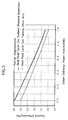
- FIG. 5 shows the thermal efficiency of a partial regenerative dual fluid cycle gas turbine assembly of the present invention compared with that of a dual fluid cycle gas turbine of the prior art.
- the units of the abscissa of FIG. 5 are defined as the ratio of the amount of steam delivered per power output (ton/h/MW).
- the partial rege nerative dual fluid cycle gas turbine of the present invention because it recovers turbine exhaust heat by the mixture of part of the compressed air bled from the compressor outlet and the saturate steam generated by the recovery of the turbine exhaust heat, minimizes the energy loss in the exhaust heat recovery system.
- the thermal efficiency of the entire assembly can thus be remarkably improved, compared with a turbine exhaust heat recovery method carried out by only using a steam superheater, as in the dual fluid cycle gas turbine of the prior art ( Figure 8).
- the advantages obtained by the present invention are not limited to within the ranges of ton/h/MW shown in FIGS. 5, 6 and 7. Advantageous effects are obtained up to about 3 ton/h/MW.
- FIG. 6 shows injected steam per unit powers versus steam delivery per unit power for both the present invention and a dual fluid cycle turbine of the prior art.
- FIG. 7 shows that the relative power output versus steam delivery per unit power output is greater for the gas turbine of the present invention.
- This greater relative power output is because the amount of the steam injected is not as great as in the dual fluid cycle gas turbine of the prior art as shown in Fig.6.
- This advantageous effect is again due to the injection into combustor 2 of a mixture of steam and compressed air after the addition of heat to the mixture in heat exchanger 12. Accordingly, the variation of the flow rate in the turbine is not as great as in the dual fluid cycle gas turbine of the prior art.
- the power is not decreased as much as the dual fluid cycle gas turbine of the prior art if the amount of utility steam delivered is increased while the amount of the steam injected into the combustor is decreased.
- the gas turbine assembly of the present invention is provided with a mixer for mixing steam and compressed air, and the mixed gas is fed to the combustor after having been pre-heated by the heat exchanger, the amount of the steam needed to be generated by the turbine exhaust heat can be reduced and the thermal efficiency thereof can be increased. Accordingly, variations of the power and the thermal efficiency of the gas turbine assembly can be minimized even if the amount of the steam injected into the combustor is changed.
- the mixer can boost the air using the steam as a power source, it is possible to compensate pressure loss in the air line and to improve the overall thermal efficiency of the gas turbine assembly.
Applications Claiming Priority (2)
| Application Number | Priority Date | Filing Date | Title |
|---|---|---|---|
| JP5037217A JPH0826780B2 (ja) | 1993-02-26 | 1993-02-26 | 部分再生式二流体ガスタービン |
| JP37217/93 | 1993-02-26 |
Publications (2)
| Publication Number | Publication Date |
|---|---|
| EP0619417A1 true EP0619417A1 (fr) | 1994-10-12 |
| EP0619417B1 EP0619417B1 (fr) | 1997-06-11 |
Family
ID=12491428
Family Applications (1)
| Application Number | Title | Priority Date | Filing Date |
|---|---|---|---|
| EP94102820A Expired - Lifetime EP0619417B1 (fr) | 1993-02-26 | 1994-02-24 | Turbine à gaz |
Country Status (4)
| Country | Link |
|---|---|
| US (1) | US5417053A (fr) |
| EP (1) | EP0619417B1 (fr) |
| JP (1) | JPH0826780B2 (fr) |
| DE (1) | DE69403719T2 (fr) |
Cited By (7)
| Publication number | Priority date | Publication date | Assignee | Title |
|---|---|---|---|---|
| WO1998001658A1 (fr) * | 1996-07-10 | 1998-01-15 | Vattenfall Ab (Publ.) | Procede et dispositif pour produire du travail mecanique et, si desire, de la chaleur, dans une turbine a evaporation de gaz |
| EP0851099A3 (fr) * | 1996-12-27 | 2000-11-22 | Ishikawajima-Harima Heavy Industries Co., Ltd. | Générateur à turbine à gaz |
| WO2000079104A1 (fr) | 1999-06-18 | 2000-12-28 | Jordan Borislavov Kolev | Systeme de compression et d'ejection pour moteurs a pistons |
| WO2006094324A2 (fr) * | 2005-03-11 | 2006-09-14 | Delunamagma Industries Gmbh | Moteur a combustion interne comportant une pompe a jet de vapeur servant d'etage de compression |
| WO2009124538A2 (fr) | 2008-04-11 | 2009-10-15 | Eduard Alper Bolkan | Dispositif d'alimentation en vapeur d'eau via un échangeur de chaleur dans une chambre de combustion, et procédé associé |
| US8671688B2 (en) | 2011-04-13 | 2014-03-18 | General Electric Company | Combined cycle power plant with thermal load reduction system |
| US9222410B2 (en) | 2011-04-13 | 2015-12-29 | General Electric Company | Power plant |
Families Citing this family (24)
| Publication number | Priority date | Publication date | Assignee | Title |
|---|---|---|---|---|
| US6170264B1 (en) | 1997-09-22 | 2001-01-09 | Clean Energy Systems, Inc. | Hydrocarbon combustion power generation system with CO2 sequestration |
| ES2139490B1 (es) * | 1996-10-30 | 2001-03-16 | Univ Navarra Publica | Camara de mezcla para gases de escape calientes con aire frio. |
| JPH11324710A (ja) | 1998-05-20 | 1999-11-26 | Hitachi Ltd | ガスタービン発電プラント |
| DE19918346A1 (de) * | 1999-04-22 | 2000-10-26 | Asea Brown Boveri | Verfahren und Vorrichtung zur schnellen Leistungssteigerung und Sicherstellung einer Zusatzleistung einer Gasturbinenanlage |
| US6247316B1 (en) | 2000-03-22 | 2001-06-19 | Clean Energy Systems, Inc. | Clean air engines for transportation and other power applications |
| AU2001276823A1 (en) * | 2000-05-12 | 2001-12-03 | Clean Energy Systems, Inc. | Semi-closed brayton cycle gas turbine power systems |
| JP4030432B2 (ja) * | 2001-04-09 | 2008-01-09 | 株式会社日立製作所 | ガスタービン発電装置 |
| US6644012B2 (en) * | 2001-11-02 | 2003-11-11 | Alston (Switzerland) Ltd | Gas turbine set |
| WO2003049122A2 (fr) * | 2001-12-03 | 2003-06-12 | Clean Energy Systems, Inc. | Systemes de production alimente en charbon et en gaz de synthese a emission atmospherique zero |
| DK3078909T3 (da) * | 2002-10-10 | 2022-08-15 | Lpp Comb Llc | Metode til fordampning af flydende brændstoffer til forbrænding |
| US6945029B2 (en) * | 2002-11-15 | 2005-09-20 | Clean Energy Systems, Inc. | Low pollution power generation system with ion transfer membrane air separation |
| WO2004081479A2 (fr) * | 2003-03-10 | 2004-09-23 | Clean Energy Systems, Inc. | Systemes de generation d'energie a echangeur rechauffeur |
| US20050241311A1 (en) | 2004-04-16 | 2005-11-03 | Pronske Keith L | Zero emissions closed rankine cycle power system |
| PL1825194T3 (pl) * | 2004-12-08 | 2021-09-20 | Lpp Combustion, Llc | Sposób i urządzenie do kondycjonowania ciekłych paliw węglowodorowych |
| EP1828549B1 (fr) * | 2004-12-23 | 2013-01-23 | Alstom Technology Ltd | Centrale electrique |
| WO2007021909A2 (fr) * | 2005-08-10 | 2007-02-22 | Clean Energy Systems, Inc. | Production d'hydrogene a partir d'un bruleur oxy-combustible |
| JP2006052738A (ja) * | 2005-11-04 | 2006-02-23 | Kawasaki Heavy Ind Ltd | ガスタービンプラント |
| US8529646B2 (en) * | 2006-05-01 | 2013-09-10 | Lpp Combustion Llc | Integrated system and method for production and vaporization of liquid hydrocarbon fuels for combustion |
| BRPI1014209A2 (pt) * | 2009-03-26 | 2016-04-05 | Fadi Eldabbagh | "sistema para reduzir emissões e melhorar eficiência de energia em sistemas de combustão de combustíveis fósseis e biocombustíveis." |
| US9297316B2 (en) * | 2011-11-23 | 2016-03-29 | General Electric Company | Method and apparatus for optimizing the operation of a turbine system under flexible loads |
| WO2014080984A1 (fr) | 2012-11-22 | 2014-05-30 | Uji Shigekazu | Dispositif pour récupérer les composés organiques volatils |
| JP6137831B2 (ja) * | 2012-12-28 | 2017-05-31 | 三菱日立パワーシステムズ株式会社 | 高湿分空気利用ガスタービンコージェネレーションシステム |
| KR102011067B1 (ko) * | 2018-03-07 | 2019-10-14 | 두산중공업 주식회사 | 가스 터빈 및 가스 터빈의 구동 방법 |
| US11199361B2 (en) * | 2019-02-19 | 2021-12-14 | Gas Technology Institute | Method and apparatus for net zero-water power plant cooling and heat recovery |
Citations (8)
| Publication number | Priority date | Publication date | Assignee | Title |
|---|---|---|---|---|
| US2482819A (en) * | 1947-12-23 | 1949-09-27 | Comb Eng Superheater Inc | Reciprocating engine plant with gas turbine cycle and submerged combustion boiler |
| FR1168070A (fr) * | 1955-12-09 | 1958-12-04 | Installation génératrice de vapeur et de puissance | |
| US3353360A (en) * | 1966-02-18 | 1967-11-21 | Foster Wheeler Corp | Power plant with steam injection |
| GB1104075A (en) * | 1965-01-26 | 1968-02-21 | Inst Teoreticheskoi I Prikladn | Method of combustion of high-sulphur ash fuels at thermal power stations |
| FR2101936A5 (fr) * | 1970-08-12 | 1972-03-31 | Sulzer Ag | |
| DE2332698A1 (de) * | 1972-07-06 | 1974-01-17 | Steag Ag | Verfahren zum betrieb einer gasturbinenanlage und fuer das verfahren eingerichtete gasturbinenanlage |
| EP0041873A1 (fr) * | 1980-06-11 | 1981-12-16 | Mitsubishi Gas Chemical Company, Inc. | Système échangeur de chaleur d'un moteur thermique |
| EP0081996A2 (fr) * | 1981-12-10 | 1983-06-22 | Mitsubishi Gas Chemical Company, Inc. | Cycle de turbine à gaz avec récupération de chaleur |
Family Cites Families (4)
| Publication number | Priority date | Publication date | Assignee | Title |
|---|---|---|---|---|
| US4041699A (en) * | 1975-12-29 | 1977-08-16 | The Garrett Corporation | High temperature gas turbine |
| EP0081995B1 (fr) * | 1981-12-10 | 1987-03-11 | Mitsubishi Gas Chemical Company, Inc. | Cycle de turbine à gaz avec récupération de chaleur |
| US4660367A (en) * | 1983-03-03 | 1987-04-28 | Murata Kikai Kabushiki Kaisha | Bobbin transporting apparatus |
| US5271216A (en) * | 1990-06-19 | 1993-12-21 | Asea Brown Boveri Ltd. | Method for increasing the compressor-related pressure drop of the gas turbine of a power plant |
-
1993
- 1993-02-26 JP JP5037217A patent/JPH0826780B2/ja not_active Expired - Lifetime
-
1994
- 1994-01-25 US US08/186,155 patent/US5417053A/en not_active Expired - Lifetime
- 1994-02-24 DE DE69403719T patent/DE69403719T2/de not_active Expired - Lifetime
- 1994-02-24 EP EP94102820A patent/EP0619417B1/fr not_active Expired - Lifetime
Patent Citations (8)
| Publication number | Priority date | Publication date | Assignee | Title |
|---|---|---|---|---|
| US2482819A (en) * | 1947-12-23 | 1949-09-27 | Comb Eng Superheater Inc | Reciprocating engine plant with gas turbine cycle and submerged combustion boiler |
| FR1168070A (fr) * | 1955-12-09 | 1958-12-04 | Installation génératrice de vapeur et de puissance | |
| GB1104075A (en) * | 1965-01-26 | 1968-02-21 | Inst Teoreticheskoi I Prikladn | Method of combustion of high-sulphur ash fuels at thermal power stations |
| US3353360A (en) * | 1966-02-18 | 1967-11-21 | Foster Wheeler Corp | Power plant with steam injection |
| FR2101936A5 (fr) * | 1970-08-12 | 1972-03-31 | Sulzer Ag | |
| DE2332698A1 (de) * | 1972-07-06 | 1974-01-17 | Steag Ag | Verfahren zum betrieb einer gasturbinenanlage und fuer das verfahren eingerichtete gasturbinenanlage |
| EP0041873A1 (fr) * | 1980-06-11 | 1981-12-16 | Mitsubishi Gas Chemical Company, Inc. | Système échangeur de chaleur d'un moteur thermique |
| EP0081996A2 (fr) * | 1981-12-10 | 1983-06-22 | Mitsubishi Gas Chemical Company, Inc. | Cycle de turbine à gaz avec récupération de chaleur |
Non-Patent Citations (1)
| Title |
|---|
| MAKANSKI: "Brayton Cycles challenge Rankine for dominance", POWER, vol. 133, no. 6, 1 June 1989 (1989-06-01), NEW YORK US, pages 43 - 48, XP000114268 * |
Cited By (9)
| Publication number | Priority date | Publication date | Assignee | Title |
|---|---|---|---|---|
| WO1998001658A1 (fr) * | 1996-07-10 | 1998-01-15 | Vattenfall Ab (Publ.) | Procede et dispositif pour produire du travail mecanique et, si desire, de la chaleur, dans une turbine a evaporation de gaz |
| EP0851099A3 (fr) * | 1996-12-27 | 2000-11-22 | Ishikawajima-Harima Heavy Industries Co., Ltd. | Générateur à turbine à gaz |
| WO2000079104A1 (fr) | 1999-06-18 | 2000-12-28 | Jordan Borislavov Kolev | Systeme de compression et d'ejection pour moteurs a pistons |
| WO2006094324A2 (fr) * | 2005-03-11 | 2006-09-14 | Delunamagma Industries Gmbh | Moteur a combustion interne comportant une pompe a jet de vapeur servant d'etage de compression |
| WO2006094324A3 (fr) * | 2005-03-11 | 2007-02-01 | Siegfried Nagel | Moteur a combustion interne comportant une pompe a jet de vapeur servant d'etage de compression |
| WO2009124538A2 (fr) | 2008-04-11 | 2009-10-15 | Eduard Alper Bolkan | Dispositif d'alimentation en vapeur d'eau via un échangeur de chaleur dans une chambre de combustion, et procédé associé |
| WO2009124538A3 (fr) * | 2008-04-11 | 2010-04-01 | Eduard Alper Bolkan | Dispositif d'alimentation en vapeur d'eau via un échangeur de chaleur dans une chambre de combustion, et procédé associé |
| US8671688B2 (en) | 2011-04-13 | 2014-03-18 | General Electric Company | Combined cycle power plant with thermal load reduction system |
| US9222410B2 (en) | 2011-04-13 | 2015-12-29 | General Electric Company | Power plant |
Also Published As
| Publication number | Publication date |
|---|---|
| JPH06248974A (ja) | 1994-09-06 |
| JPH0826780B2 (ja) | 1996-03-21 |
| DE69403719T2 (de) | 1997-09-18 |
| US5417053A (en) | 1995-05-23 |
| DE69403719D1 (de) | 1997-07-17 |
| EP0619417B1 (fr) | 1997-06-11 |
Similar Documents
| Publication | Publication Date | Title |
|---|---|---|
| US5417053A (en) | Partial regenerative dual fluid cycle gas turbine assembly | |
| JP3646834B2 (ja) | ガスタービン発電装置 | |
| US5319925A (en) | Installation for generating electrical energy | |
| US5495709A (en) | Air reservoir turbine | |
| US20010039797A1 (en) | Advanced Cheng combined cycle | |
| US6499303B1 (en) | Method and system for gas turbine power augmentation | |
| US4785621A (en) | Air bottoming cycle for coal gasification plant | |
| US5363642A (en) | Method of operating a gas turbine group | |
| EP1069282B1 (fr) | Système de turbine à gaz à régénération partielle, à double pression et à injection de vapeur | |
| JPH08510311A (ja) | 中間冷却と復熱を用いた高能率多軸再熱タービン | |
| US5581128A (en) | Gas-turbine and steam-turbine based electric power generation system with an additional auxiliary steam turbine to compensate load fluctuations | |
| CA2319663C (fr) | Turbine a gaz avec installation combinee | |
| JP3009712B2 (ja) | 蒸気動力ステーションの始動運転のための蒸気及び動力の形成方法及びその設備 | |
| JP3804204B2 (ja) | 多段タービン圧縮機を備えた燃料電池発電装置 | |
| US5271216A (en) | Method for increasing the compressor-related pressure drop of the gas turbine of a power plant | |
| JPH05248262A (ja) | ガスターボ群 | |
| JP2544453B2 (ja) | タ―ビンプラント | |
| JP2751837B2 (ja) | 二流体サイクルガスタービン | |
| JPS6332127A (ja) | ガスタ−ビン駆動設備 | |
| JPH08166109A (ja) | 加圧流動床プラント | |
| JP2003120322A (ja) | 蒸気噴射ガスタービン発電装置 | |
| JPS6242209B2 (fr) | ||
| JPH09203327A (ja) | ガスタービン発電装置 | |
| JPH11280493A (ja) | 複合蒸気噴射ガスタービン | |
| JPS5923034A (ja) | 高圧熱風発生装置の起動装置 |
Legal Events
| Date | Code | Title | Description |
|---|---|---|---|
| PUAI | Public reference made under article 153(3) epc to a published international application that has entered the european phase |
Free format text: ORIGINAL CODE: 0009012 |
|
| AK | Designated contracting states |
Kind code of ref document: A1 Designated state(s): DE FR GB |
|
| 17P | Request for examination filed |
Effective date: 19950209 |
|
| 17Q | First examination report despatched |
Effective date: 19960123 |
|
| GRAG | Despatch of communication of intention to grant |
Free format text: ORIGINAL CODE: EPIDOS AGRA |
|
| RAP1 | Party data changed (applicant data changed or rights of an application transferred) |
Owner name: ISHIKAWAJIMA-HARIMA HEAVY INDUSTRIES CO., LTD. |
|
| GRAH | Despatch of communication of intention to grant a patent |
Free format text: ORIGINAL CODE: EPIDOS IGRA |
|
| GRAH | Despatch of communication of intention to grant a patent |
Free format text: ORIGINAL CODE: EPIDOS IGRA |
|
| GRAA | (expected) grant |
Free format text: ORIGINAL CODE: 0009210 |
|
| AK | Designated contracting states |
Kind code of ref document: B1 Designated state(s): DE FR GB |
|
| ET | Fr: translation filed | ||
| REF | Corresponds to: |
Ref document number: 69403719 Country of ref document: DE Date of ref document: 19970717 |
|
| PLBE | No opposition filed within time limit |
Free format text: ORIGINAL CODE: 0009261 |
|
| STAA | Information on the status of an ep patent application or granted ep patent |
Free format text: STATUS: NO OPPOSITION FILED WITHIN TIME LIMIT |
|
| 26N | No opposition filed | ||
| REG | Reference to a national code |
Ref country code: GB Ref legal event code: IF02 |
|
| PGFP | Annual fee paid to national office [announced via postgrant information from national office to epo] |
Ref country code: DE Payment date: 20130220 Year of fee payment: 20 Ref country code: GB Payment date: 20130220 Year of fee payment: 20 Ref country code: FR Payment date: 20130301 Year of fee payment: 20 |
|
| REG | Reference to a national code |
Ref country code: DE Ref legal event code: R071 Ref document number: 69403719 Country of ref document: DE |
|
| REG | Reference to a national code |
Ref country code: DE Ref legal event code: R071 Ref document number: 69403719 Country of ref document: DE |
|
| REG | Reference to a national code |
Ref country code: GB Ref legal event code: PE20 Expiry date: 20140223 |
|
| PG25 | Lapsed in a contracting state [announced via postgrant information from national office to epo] |
Ref country code: GB Free format text: LAPSE BECAUSE OF EXPIRATION OF PROTECTION Effective date: 20140223 Ref country code: DE Free format text: LAPSE BECAUSE OF EXPIRATION OF PROTECTION Effective date: 20140225 |