EP0618698A1 - Optische Vorrichtung zur Taktrückgewinnung eines kodierten Signales - Google Patents
Optische Vorrichtung zur Taktrückgewinnung eines kodierten Signales Download PDFInfo
- Publication number
- EP0618698A1 EP0618698A1 EP94400645A EP94400645A EP0618698A1 EP 0618698 A1 EP0618698 A1 EP 0618698A1 EP 94400645 A EP94400645 A EP 94400645A EP 94400645 A EP94400645 A EP 94400645A EP 0618698 A1 EP0618698 A1 EP 0618698A1
- Authority
- EP
- European Patent Office
- Prior art keywords
- signal
- circuit
- optical
- coded signal
- coded
- Prior art date
- Legal status (The legal status is an assumption and is not a legal conclusion. Google has not performed a legal analysis and makes no representation as to the accuracy of the status listed.)
- Withdrawn
Links
Images

Classifications
-
- H—ELECTRICITY
- H04—ELECTRIC COMMUNICATION TECHNIQUE
- H04L—TRANSMISSION OF DIGITAL INFORMATION, e.g. TELEGRAPHIC COMMUNICATION
- H04L7/00—Arrangements for synchronising receiver with transmitter
- H04L7/0075—Arrangements for synchronising receiver with transmitter with photonic or optical means
Definitions
- the subject of the present invention is an optical device making it possible to recover the rhythm (also called a clock) of a signal coded by a digital code. It finds numerous applications in the field of digital transmission by optical fibers.
- the object of the present invention is precisely to remedy this drawback. To this end, it offers an optical device for recovering the clock of signals coded according to different digital codes such as the NRZ (No Return to Zero) code where each information bit at "1" has a duration of a period clock, CMI code (Code Mark Inversion) where the information bits are coded alternately "01" and "10", the biphase code, etc ...
- NRZ No Return to Zero
- CMI code Code Mark Inversion
- the interferometer is a MACH-ZEHNDER interferometer, made of optical fibers.
- the circuit for shaping the coded signal comprises an AM / FM converter associated in series with the interferometer, to convert the amplitude modulated signal into a frequency modulated signal.
- This AM / FM converter is preferably a laser converter.
- An optical filter can, moreover, be associated in series with the AM / FM converter, and be adjusted to one of the frequencies of the frequency modulated signal to ensure the establishment of a logic function, the choice of the logic function to establish dependent on the digital code of the coded signal.
- the rhythm recovery circuit comprises a two-to-two coupler making it possible to introduce the pulses coming from the circuit for shaping the coded signal and to carry out the feedback loop.
- the two-to-two coupler is made of optical fibers.
- the rhythm recovery circuit includes an amplifier and an optical filter associated in series in the feedback loop.
- the rhythm recovery device can include an optical equalizer connected to the second output of the recovery circuit.
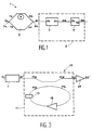
- FIG 1 there is shown schematically the circuit for shaping the coded signal received by the device according to the invention.
- This circuit for shaping the coded signal is referenced 1; we will therefore write indifferently, in the following description, circuit 1 and circuit for shaping the coded signal.
- This circuit for shaping the coded signal includes an interferometer 3.
- the signal coded according to any one of the known digital codes is introduced into the shaping circuit. by input 3a of the interferometer 3.
- This signal coded by a digital code, also called initial signal, is referenced Si.
- This signal Si is therefore injected into the interferometer 3, which is preferably a MACH interferometer -ZEHNDER.
- This MACH-ZEHNDER interferometer has the advantage of being easily achievable in optical fibers.
- the interferometer 3 is made of optical fibers so as to allow the continuity of the propagation of the signal If transmitted to device 1 by fiber optic links.
- the signal Si when it is introduced into the interferometer 3, is able to follow two paths, namely the path Ta and the path Tb.
- the delay R between the two paths that is to say the path difference between the paths Ta and Tb, is substantially equal to T / 2.
- the signals used in the interferometer for the path Ta and for the path Tb are, respectively, referenced Sa and Sb. These signals Sa and Sb are shown in Figure 3 attached which will be described in more detail in the following description.
- These signals Sa and Sb are offset by about half a period T / 2 by the interferometer.
- the signal Sc obtained at the output 3b of the interferometer 3 is the signal resulting from the signals Sa and Sb.
- This optical signal Sc then has three amplitude levels, A1, A2, A3, as shown in FIG. 3.
- R N x T / 2> rx Lc
- N is an integer
- T is the propagation time of the signals in the fiber (approximately 5 ns / m)
- the signal Sc obtained at the output of the interferometer 3 is injected into a generator 9 of optical logic functions.
- This generator includes a 5 AM / FM converter associated with an optical filter.
- the converter 5 makes it possible in particular to convert the amplitude modulated signals from the interferometer 3 into frequency modulated signals.
- This converter 5 is preferably of the laser type.
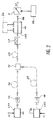
- An embodiment of the generator 9 of logic functions is represented in FIG. 2. This generator of logic functions is capable of supplying at its output a logic function, in optical form, which is reconfigurable, that is to say that the 'We can choose this logic function among several logic functions achievable with this generator.
- this generator uses an optical transposition in a distributed feedback laser diode which it comprises, as well as an optical filter 7 tunable in frequency.
- a distributed feedback laser diode which it comprises, as well as an optical filter 7 tunable in frequency.
- Such an optical transposition is described in the document: "Wavenlength conversion for FM light using light injection induced frequency shift in DFB-LD", by K INOUE and N. TAKATO, published in Electronics Letters, 28 September 1989, vol. 25, n ° 20, p. 1360-62.
- the laser diode LD1 at the output of which an optical isolator 14 is placed, is connected by an optical fiber 16 to an input of the optical coupler 10.
- the laser diode LD2 at the output of which an optical isolator 18 is placed, is connected by an optical fiber 20 to the other input of the optical coupler 10.
- the light capable of being supplied by the output of the optical coupler 10 is sent to the laser diode LD3 via an optical fiber 22 and injected into the active layer of this laser diode LD3.
- the LD3 laser diode which has two polarization electrodes, is provided with control means 24 provided to send respectively to these electrodes two constant polarization currents, chosen so that the LD3 laser diode is single mode and provides a beam output. laser 26.
- the wavelength of the output light beam 26 is the quiescent wavelength LO of the laser diode LD3.
- the optical frequency corresponding to this wavelength LO is denoted F1.
- the optical filter 7, which is frequency tunable, is placed at the output of the laser diode LD3 and intended to select an optical frequency from the optical frequencies of the light signals capable of being supplied by the laser diode LD3.
- This optical filter 7 can be controlled by appropriate means 28.
- the laser diodes LD1 and LD2 are respectively controlled by the signal Sc from the interferometer 3.
- the laser diodes LD1 and LD2 being controlled by the same signal, they respectively emit digital optical signals S1 and S2 which are synchronous and have the same bit rate.
- optical signals are mixed by the optical coupler 10 and are injected simultaneously into the active layer of the laser diode LD3.
- a polarization controller CP is placed at the input of the laser diode LD3 in order to give the signals S1 and S2 leaving the optical fiber 22 a direction of polarization situated in the plane of polarization of the laser diode LD3 ( plane of the active layer of this LD3 laser diode).
- Each of the optical signals S1 and S2 is a series of high levels (logic levels 1) and low levels (logic levels 0).
- the light power injected into the LD3 laser diode varies over time.
- the light power injected into the laser diode LD3 is zero.
- the optical frequency of the light beam 26 emitted by this laser diode LD3 is the quiescent frequency FO of the laser diode LD3.
- the light power injected into this laser diode LD3 is not zero and the frequency of the light signal supplied by the laser diode LD3 slides to a value F2 greater than F1.
- the light power injected into the laser diode LD3 is the maximum light power that can be obtained with the signals S1 and S2.
- the optical frequency of the light signal 26 supplied by the laser diode LD3 slides, in this case c), up to a value F3 greater than F2.
- the digital optical signal Sd which is obtained at the output of the optical filter 7 tunable in frequency is a function of what the optical filter has selected as frequency: the frequency F1, the frequency F2 or the frequency F3.
- optical filter 7 makes it possible to select one of the three logical functions AND (AND in the articles in English language), NON AND (NAND in the articles in English language) and EXCLUSIVE OR (XOR in the articles in English language) .
- the digital optical signal Sd supplied by the optical filter 7 corresponds to the NAND logic function.
- this digital optical signal Sd corresponds to the logic function OR EXCLUSIVE.
- this digital optical signal Sd corresponds to the logic function AND.
- This frequency-tunable optical filter 7 can be a tunable Perot Fabry interferometer.
- the frequency tunable optical filter 7 is constituted by an auxiliary laser diode with distributed feedback which is polarized below its threshold current by appropriate means.
- This auxiliary laser diode has two polarization electrodes and it is by adjusting the value of the polarization currents respectively supplied by appropriate means that the value of the frequency selected by this auxiliary laser diode forming the optical filter is chosen.
- the signal Sd supplied on the output 5b of the converter 5 is therefore a frequency modulated signal on three frequencies F1, F2, F3, the temporal duration of the states of which has not been modified.
- This signal Sd is then introduced into the optical filter 7 by the input 7a of said filter which is connected to the output 5b of the converter 5.
- This optical filter can, for example, be adjusted to the frequency F2 so that the generator 9 of functions logic establishes the OU-EXCLUSIVE function.
- the optical logic function to be established is the OR-EXCLUSIVE function.
- This OR-EXCLUSIVE function is carried out by adjusting the optical filter 7 on the frequency F2 of the signal SD introduced into said optical filter 7.
- the generator 9 of logic functions can establish the AND logic function in order to recover the clock of a signal coded by a two-phase code.
- the signal Se supplied by the output 7b of the filter 7 meets the conditions necessary to allow the implementation of the circuit for recovering the rhythm of the coded signal. These conditions are, as has been given previously, that the signal Se which is a series of pulses, has pulses of duration equal to the half clock period T / 2 and of variable occurrence equal to N x T, where the coefficient N is a time-varying integer whose maximum value depends essentially on the code of the coded signal introduced in circuit 1.
- FIG. 3 the circuit for recovering the rhythm of the coded signal is shown diagrammatically. This rhythm recovery circuit is referenced 19; we will therefore talk about circuit 19.
- This rhythm recovery circuit 19 is connected to the output 7b of the circuit 1 for shaping the coded signal.
- This circuit 19 includes a 2 to 2 coupler.
- this coupler is made of optical fibers, so as to allow continuity of the propagation of the optical signal Se obtained at the output of the shaping circuit 1.
- This 2 to 2 coupler referenced 11 in FIG. 3, has a first and a second input, respectively 11a and 11b, and a first and a second output, respectively 11c and 11d.
- the input 11a receives the signal from the output of the shaping circuit 1.
- This signal is referenced Sf in FIG. 3; it corresponds to the signal Se of FIG. 1; it however carries a different reference so as to ensure consistency between the signals Sf and Sg of FIG. 3 which are represented, in FIG. 4, in a time reference different from the signal referenced Se.
- the output 11d of the clock recovery circuit 11 provides the signal Sg corresponding to the sought clock signal.
- the output 11c of the coupler 11 is connected to the input 11b of this coupler, in order to produce a feedback loop.
- An amplifier 13 and an optical filter 15 are connected in series with each other in the feedback loop, that is to say that they are connected after the output 11c and before the input 11b of the coupler. This association of the amplifier 13 and the optical filter 15 has the advantage of making it possible to adjust the length of the feedback loop, so that the propagation time of the optical signal in said feedback loop is equal to the period T of the clock that one seeks to recover.
- an optical equalizer 17 is connected to the output 11d of the coupler 11.
- This optical equalizer 17 is, according to one embodiment, an optical amplifier similar to the amplifier 13 used in the feedback loop.
- the non-linearity of the gain curve of this amplifier 17, when it operates in saturation, makes it possible to correct the amplitude variation of the pulses of the signal Sg.
- the signal obtained at the output of this optical equalizer 17 is referenced Sg '.
- optical amplifiers 13 and 17 of the semiconductor optical amplifier type are used, the propagation time of which is less than 5 pins / second.
- FIG 4 there is shown the different signals obtained during processing by the device of the invention.
- the signal represented in A is the signal Sa which is one of the signals of the two paths of the interferometer 3.
- the signal Sb is the signal obtained for the second path of the interferometer 3.
- This signal Sb, represented in B is shifted by half-period with respect to the signal shown in A.
- This half-period T / 2 is equivalent to the delay R allocated by the interferometer 3 on the signal flowing in the path Tb with respect to the signal flowing in the path Ta.
- these signals Sa and Sb, represented respectively at A and B are substantially identical to the coded signal Si but shifted in time by half a period for the signal Sb.
- the signal shown in C that is to say the signal Sc obtained at the output of the interferometer 3, is a signal resulting from the sum of the signals Sa and Sb.
- This signal Sc is an amplitude modulated signal according to three levels A1, A2, A3, as shown in FIG. 4.
- the signal Sd represented at D in FIG. 43 shows the signal obtained at the output of the converter 5, that is to say that it shows the frequency modulated signal.
- This signal Sd has three frequency levels, F1, F2, F3; the states of this signal Sd are identical from the time duration point of view to those of the signal Sc amplitude modulated.
- the signal Se represented at E in FIG. 4 shows the signal obtained at the output of circuit 1 for shaping the coded signal.
- This signal Se is the signal obtained after adjustment on the frequency F2 by the optical filter 7.
- This signal Se is therefore frequency modulated according to two levels, F1 and F2.
- the signals Sf and Sg represented at F and at G correspond to the signals which are at the input and at the output of the circuit 11 for clock recovery.
- the signal Sf represented at F represents the same signal as the signal Se, but in a time frame different from that of Se. Indeed, the signals represented in F and G illustrate the signals which one would obtain on an oscillator placed in entry and exit of the circuit 19 clock recovery. Thus, the signal Sf illustrates the pulses obtained at the output of the circuit 1 for shaping the coded signal.
- the signal Sg represented in G, shows the clock signal obtained at the output of the coupler 11, that is to say the clock signal sought.
Landscapes
- Physics & Mathematics (AREA)
- Optics & Photonics (AREA)
- Engineering & Computer Science (AREA)
- Computer Networks & Wireless Communication (AREA)
- Signal Processing (AREA)
- Optical Communication System (AREA)
Applications Claiming Priority (2)
| Application Number | Priority Date | Filing Date | Title |
|---|---|---|---|
| FR9303592 | 1993-03-29 | ||
| FR9303592A FR2703547B1 (fr) | 1993-03-29 | 1993-03-29 | Dispositif optique de récupération du rythme d'un signal code. |
Publications (1)
| Publication Number | Publication Date |
|---|---|
| EP0618698A1 true EP0618698A1 (de) | 1994-10-05 |
Family
ID=9445450
Family Applications (1)
| Application Number | Title | Priority Date | Filing Date |
|---|---|---|---|
| EP94400645A Withdrawn EP0618698A1 (de) | 1993-03-29 | 1994-03-25 | Optische Vorrichtung zur Taktrückgewinnung eines kodierten Signales |
Country Status (4)
| Country | Link |
|---|---|
| US (1) | US5434692A (de) |
| EP (1) | EP0618698A1 (de) |
| JP (1) | JPH07147562A (de) |
| FR (1) | FR2703547B1 (de) |
Families Citing this family (13)
| Publication number | Priority date | Publication date | Assignee | Title |
|---|---|---|---|---|
| IT1276122B1 (it) * | 1995-11-14 | 1997-10-24 | Pirelli Cavi Spa | Metodo e dispositivo per recuperare in via ottica il sincronismo di un segnale ottico digitale |
| US6388753B1 (en) * | 1996-03-14 | 2002-05-14 | Massachusetts Institute Of Technology | All-optical bit phase sensing and clock recovery apparatus and methods |
| GB2320635A (en) * | 1996-12-19 | 1998-06-24 | Northern Telecom Ltd | Optical timing detection using an interferometer |
| EP0854379B1 (de) | 1996-12-19 | 2010-11-03 | Nortel Networks Limited | Interferometer für rein optische Taktrückgewinnung |
| GB2320634A (en) | 1996-12-19 | 1998-06-24 | Northern Telecom Ltd | Optical sampling by using an interferometer to modulate a pulse train |
| KR100264533B1 (ko) * | 1997-12-17 | 2000-09-01 | 정선종 | 광데이터형태변환시스템의소광비를향상시키는장치및이를이용한광변조시스템 |
| US6222669B1 (en) | 1999-04-14 | 2001-04-24 | Nortel Networks Limited | Optical partial regeneration of solitons |
| US6636318B2 (en) | 2000-10-06 | 2003-10-21 | Alphion Corp. | Bit-rate and format insensitive all-optical circuit for reshaping, regeneration and retiming of optical pulse streams |
| AU2002213010A1 (en) * | 2000-10-06 | 2002-04-22 | Alphion Corporation | Bit-rate and format insensitive all-optical clock extraction circuit |
| US6563621B2 (en) | 2000-10-06 | 2003-05-13 | Alphion Corporation | Bit-rate and format insensitive all-optical clock extraction circuit |
| US20020080450A1 (en) * | 2000-12-27 | 2002-06-27 | Hait John N. | Fully photonic, high-speed, reduced-energy-density, burst generator |
| EP1590901A2 (de) * | 2003-02-07 | 2005-11-02 | Kodeos Communications, Inc. | Gefilterter dreiebenensender |
| US7319555B2 (en) * | 2005-04-27 | 2008-01-15 | Alphion Corporation | Integrated performance monitoring, performance maintenance, and failure detection for photonic regenerators |
Citations (5)
| Publication number | Priority date | Publication date | Assignee | Title |
|---|---|---|---|---|
| EP0198701A2 (de) * | 1985-04-17 | 1986-10-22 | Nec Corporation | Phasendetektionsschaltung |
| JPS63177626A (ja) * | 1987-01-19 | 1988-07-21 | Nippon Telegr & Teleph Corp <Ntt> | 光タイミング抽出回路 |
| JPH01150121A (ja) * | 1987-12-07 | 1989-06-13 | Nippon Telegr & Teleph Corp <Ntt> | 自己タイミング抽出光回路 |
| JPH036541A (ja) * | 1989-06-02 | 1991-01-14 | Matsushita Electric Ind Co Ltd | クロック抽出装置 |
| FR2681747A1 (fr) * | 1991-09-20 | 1993-03-26 | Thomson Csf | Dispositif de restitution d'horloge utilisant un filtre a onde de surface. |
Family Cites Families (3)
| Publication number | Priority date | Publication date | Assignee | Title |
|---|---|---|---|---|
| JPH0322855A (ja) * | 1989-06-20 | 1991-01-31 | Matsushita Electric Ind Co Ltd | アウタロータ形ブラシレスモータ |
| JP2701608B2 (ja) * | 1991-07-29 | 1998-01-21 | 日本電気株式会社 | 光クロック抽出回路 |
| JP3006541U (ja) | 1994-07-11 | 1995-01-24 | 住友ゴム工業株式会社 | キャディバッグ |
-
1993
- 1993-03-29 FR FR9303592A patent/FR2703547B1/fr not_active Expired - Fee Related
-
1994
- 1994-03-21 US US08/215,189 patent/US5434692A/en not_active Expired - Fee Related
- 1994-03-25 EP EP94400645A patent/EP0618698A1/de not_active Withdrawn
- 1994-03-29 JP JP6081112A patent/JPH07147562A/ja active Pending
Patent Citations (5)
| Publication number | Priority date | Publication date | Assignee | Title |
|---|---|---|---|---|
| EP0198701A2 (de) * | 1985-04-17 | 1986-10-22 | Nec Corporation | Phasendetektionsschaltung |
| JPS63177626A (ja) * | 1987-01-19 | 1988-07-21 | Nippon Telegr & Teleph Corp <Ntt> | 光タイミング抽出回路 |
| JPH01150121A (ja) * | 1987-12-07 | 1989-06-13 | Nippon Telegr & Teleph Corp <Ntt> | 自己タイミング抽出光回路 |
| JPH036541A (ja) * | 1989-06-02 | 1991-01-14 | Matsushita Electric Ind Co Ltd | クロック抽出装置 |
| FR2681747A1 (fr) * | 1991-09-20 | 1993-03-26 | Thomson Csf | Dispositif de restitution d'horloge utilisant un filtre a onde de surface. |
Non-Patent Citations (6)
| Title |
|---|
| A.E. MOGHAZY ET AL.: "A SMALL ACQUISITION TIME DIGITAL SELF BIT SYNCHRONIZER AND DATA DETECTOR", FIRST EUROPEAN SIGNAL PROCESSING CONFERENCE, 16 September 1980 (1980-09-16), LAUSANNE , CH, pages 551 - 556, XP000808635 * |
| HANSEN P B ET AL: "A dual-drive Ti:LiNbO3 Mach-Zehnder modulator used as an optoelectronic logic gate for 10-Gb/s simultaneous multiplexing and modulation", IEEE PHOTONICS TECHNOLOGY LETTERS, vol. 4, no. 6, June 1992 (1992-06-01), NEW YORK, US, pages 592 - 593, XP000275545 * |
| K. INOUE ET AL.: "WAVELENGTH CONVERSION FOR FM LIGHT USING LIGHT INJECTION INDUCED FREQUENCY SHIFT IN DFB-LD", ELECTRONICS LETTERS., vol. 25, no. 20, 28 September 1989 (1989-09-28), STEVENAGE GB, XP000255903 * |
| PATENT ABSTRACTS OF JAPAN vol. 012, no. 449 (E - 686) 25 November 1988 (1988-11-25) * |
| PATENT ABSTRACTS OF JAPAN vol. 013, no. 409 (P - 931) 11 September 1989 (1989-09-11) * |
| PATENT ABSTRACTS OF JAPAN vol. 015, no. 116 (P - 1182) 20 March 1991 (1991-03-20) * |
Also Published As
| Publication number | Publication date |
|---|---|
| FR2703547B1 (fr) | 1995-05-12 |
| FR2703547A1 (fr) | 1994-10-07 |
| JPH07147562A (ja) | 1995-06-06 |
| US5434692A (en) | 1995-07-18 |
Similar Documents
| Publication | Publication Date | Title |
|---|---|---|
| EP0792036B1 (de) | Verfahren zur optischen Übertragung von digitalen Daten | |
| EP0783215B1 (de) | Optisches Übertragungssystem mit Verschlüsselung auf Basis von deterministischem Chaos | |
| EP0618698A1 (de) | Optische Vorrichtung zur Taktrückgewinnung eines kodierten Signales | |
| WO2013045674A1 (fr) | Methode et dispositif de synchronisation de sources d'intrication pour reseau de communication quantique | |
| FR2781322A1 (fr) | Dispositif d'emission de donnees optiques | |
| CA2220603C (fr) | Dispositif d'emission de donnees optiques | |
| EP0576358B1 (de) | Verfahren und Vorrichtung zur optischen Übertragung von Solitonen über lange Abstände | |
| EP0538122B1 (de) | Generator zur Erzeugung logischer Funktionen mittels Frequenzsetzung in einer Laserdiode mit verteilter Rückkoppelung | |
| EP0763912B1 (de) | Rein optischer Frequenzverdoppler und dieser verwendender Solitonregenerator | |
| EP0780723A1 (de) | Steuerbarer Amplitude- und Phasenmodulator und Solitonregenerator mit einem solchen Modulator | |
| EP0716486B1 (de) | Wellenlängenkonverter | |
| EP0630123A1 (de) | Einrichtung zur Regenerierung eines Impulszuges und Einrichtung zur Rückgewinnung eines zu einem modulierten Impulszug synchronisierten periodischen Signals | |
| EP0744844B1 (de) | Binärdateneinschreibungsverfahren, insbesondere optisches, und Vorrichtung zur Durchführung dieses Verfahrens | |
| EP0980538B1 (de) | Verfahren und vorrichtung zum regenerieren von solitonenfolgen | |
| EP0094866B1 (de) | Gerät für busartige wechselseitige Verbindung mit monomoden Lichtwellenleitern | |
| FR2781320A1 (fr) | Dispositif de compensation de la dispersion de polarisation des canaux dans un signal a multiplexage en longueur d'onde | |
| EP3987692B1 (de) | Kohärente detektion mit optimiertem lokalen oszillator | |
| EP0975106B1 (de) | Anordnung zum Inline-Regenerieren eines optischen Solitonsignals durch synchrone Modulation dieser Solitonen und Übertragungssystem mit einer derartigen Vorrichtung | |
| EP0434235B1 (de) | Überwachung von Tonabstand und Leistungspegel bei FSK-Lichtwellensystemen | |
| EP1508984B1 (de) | Verfahren zur Bildung von einem kodierten RZ oder NRZ Signal | |
| RU2825995C1 (ru) | Способ формирования состояний ловушек в системе с квантовым распределением ключей | |
| FR2762104A1 (fr) | Procede et dispositif de mise en forme d'un signal binaire | |
| EP3200363A1 (de) | System zur linearen optischen abtastung und kohärenten erkennung eines optischen signals | |
| FR2670638A1 (fr) | Procede et systeme de transmission optique a saut de phase. | |
| FR3096199A1 (fr) | Détection cohérente avec oscillateur local optimisé |
Legal Events
| Date | Code | Title | Description |
|---|---|---|---|
| PUAI | Public reference made under article 153(3) epc to a published international application that has entered the european phase |
Free format text: ORIGINAL CODE: 0009012 |
|
| AK | Designated contracting states |
Kind code of ref document: A1 Designated state(s): DE GB |
|
| 17P | Request for examination filed |
Effective date: 19950311 |
|
| 17Q | First examination report despatched |
Effective date: 19980223 |
|
| STAA | Information on the status of an ep patent application or granted ep patent |
Free format text: STATUS: THE APPLICATION IS DEEMED TO BE WITHDRAWN |
|
| 18D | Application deemed to be withdrawn |
Effective date: 19980707 |