EP0617548B1 - Modification des couleurs d'images - Google Patents
Modification des couleurs d'images Download PDFInfo
- Publication number
- EP0617548B1 EP0617548B1 EP94301981A EP94301981A EP0617548B1 EP 0617548 B1 EP0617548 B1 EP 0617548B1 EP 94301981 A EP94301981 A EP 94301981A EP 94301981 A EP94301981 A EP 94301981A EP 0617548 B1 EP0617548 B1 EP 0617548B1
- Authority
- EP
- European Patent Office
- Prior art keywords
- data
- colour
- unsharp
- pixel
- sharp
- Prior art date
- Legal status (The legal status is an assumption and is not a legal conclusion. Google has not performed a legal analysis and makes no representation as to the accuracy of the status listed.)
- Expired - Lifetime
Links
- 238000012986 modification Methods 0.000 title claims description 9
- 230000004048 modification Effects 0.000 title claims description 9
- 238000000034 method Methods 0.000 claims description 26
- 230000000873 masking effect Effects 0.000 claims description 15
- 238000012937 correction Methods 0.000 claims description 12
- 238000012545 processing Methods 0.000 claims description 11
- 230000006870 function Effects 0.000 description 42
- 210000003128 head Anatomy 0.000 description 9
- 238000009499 grossing Methods 0.000 description 4
- 238000006243 chemical reaction Methods 0.000 description 3
- 238000010586 diagram Methods 0.000 description 3
- 238000000926 separation method Methods 0.000 description 3
- 239000002131 composite material Substances 0.000 description 2
- 210000004209 hair Anatomy 0.000 description 2
- 239000000976 ink Substances 0.000 description 2
- 238000003491 array Methods 0.000 description 1
- 239000003086 colorant Substances 0.000 description 1
- 230000003750 conditioning effect Effects 0.000 description 1
- 238000007796 conventional method Methods 0.000 description 1
- 230000007812 deficiency Effects 0.000 description 1
- 230000001419 dependent effect Effects 0.000 description 1
- 239000000975 dye Substances 0.000 description 1
- 210000000720 eyelash Anatomy 0.000 description 1
- 238000012886 linear function Methods 0.000 description 1
- 239000000203 mixture Substances 0.000 description 1
- 230000000007 visual effect Effects 0.000 description 1
- 238000005303 weighing Methods 0.000 description 1
- 229910052724 xenon Inorganic materials 0.000 description 1
- FHNFHKCVQCLJFQ-UHFFFAOYSA-N xenon atom Chemical compound [Xe] FHNFHKCVQCLJFQ-UHFFFAOYSA-N 0.000 description 1
Images


Classifications
-
- H—ELECTRICITY
- H04—ELECTRIC COMMUNICATION TECHNIQUE
- H04N—PICTORIAL COMMUNICATION, e.g. TELEVISION
- H04N1/00—Scanning, transmission or reproduction of documents or the like, e.g. facsimile transmission; Details thereof
- H04N1/46—Colour picture communication systems
- H04N1/56—Processing of colour picture signals
- H04N1/58—Edge or detail enhancement; Noise or error suppression, e.g. colour misregistration correction
Definitions
- This invention relates to a method of modifying a colour image.
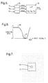
- FIG. 7 shows the relationship between the regions covered by the sharp and unsharp signals.
- the sharp signal in this instance is the value of the single pixel 70 at the current processing location.
- the unsharp signal signal is a weighted average of the 25 pixels in a 5 by 5 pixel region 71 centred on the same location.
- the weighting function may be a simple average of all pixels, ie. equal contribution from all elements, or may give greater contribution to the pixels nearer the centre.
- the regions sizes used in deriving both sharp and unsharp signals may be either smaller or larger.
- FIG. 8a shows graphs of frequency (f) against number of pixels for sharp (S) data, unsharp (U) data and the function kF(S-U) which gives the high frequency fringe data.
- Figures 8b-8e show the successive stages for addition of a thresholded difference signal (sharp minus unsharp) to the original sharp signal.
- Figure 8b shows the original sharp pixel signal S and the low-pass filtered unsharp signal U.
- the difference (S-U) is shown in Figue 8C, which also shows the threshold values (T,-T).
- the thresholded fringe signal is shown in Figure 8d and the final, enhanced output signal P is shown in Figure 8e, in which the fringe signal has been combined with the original signal.
- Such a method may be applied on the fly in a graphic arts scanner as the image is being scanned, or as a post-scan processing operation by the computer on the stored digital image.
- unsharp masking is to increase the apparent sharpness of boundaries in the image.
- unsharp masking is achieved by deriving from the picture signals sharp and unsharp signals equivalent to viewing a small area, and a large area incorporating the small area of the image, respectively. These signals are then combined in a predetermined manner so that the contrast on either side of the boundary is increased.
- the contrast on either side of the boundary is increased.
- the light area adjacent the boundary is made lighter and the dark area adjacent the boundary is made darker. This gives the visual effect of increased sharpness.
- colour correction is performed by a look-up table (LUT) operation in which the table is loaded by a colour correction function that is the composite of all the factors.
- LUT look-up table
- the problem with this method is that the sharpening of edges and fine detail is applied to all colour separations.
- the function f(S,U) may be sensitive to contrast differences between the S and U signals, where S is a sharp signal and U an unsharp signal, typically by reducing small differences and amplifying large differences, the resultant fringe signal f(S,U) is independent of the actual colour of the image. This can result in the enhancement of both the wanted edge detail and unwanted noise and grain detail present in the original film.
- Another common operational requirement is to be able to enhance or sharpen some regions of an image whilst simultaneously smoothing others.
- a very common example is in the reproduction of portrait photographs where the hair and eyelashes are made as sharp as possible, whilst the skin is to be made smooth to disguise blemishes.
- this operation must be performed as a subsequent image retouch operation with the use of one or more spatial masks to discriminate between the areas to be sharpened and smoothed and cannot be included in the scanning process.
- the apparatus for modifying an image defined by data representing the colour component content of each pixel of the image, the apparatus comprising generating means to generate unsharp (U) and sharp (S) data from the pixel data representing a selected colour component; processing means to perform an unsharp masking algorithm on the unsharp and sharp data to generate fringe data (F); means to modify the fringe data with a weighting function ( ⁇ ) ; and means for combining the modified fringe data with the pixel data representing the selected colour component to generate modified pixel data; characterised in that the apparatus further comprises means (42) to select areas of the image having different required degrees of modification, and means (43) of calculating the weighting function in accordance with the average colour and required degree of modification of each selected area, and in accordance with the values of the sharp or unsharp data for all of the colour components (U C , U M , U Y ) of the pixel.
- the fringe amplitude ie. degree of sharpening
- the fringe amplitude is varied according to the colour of the region. This enables sharpening or smoothing to be appropriate to the part of the image e.g. sharpening hair and smoothing skin colours.
- the unsharp signal values there is greater resistance to noise in the original pixel data, but sharp signal values could also be used.
- the unsharp data is determined by calculating a weighted average of the pixel data in a region (such as a 5*5 pixel square) surrounding the pixel.
- the unsharp data may be calculated as some other function of the neighbourhood pixel values.
- the sharp data is the same as the pixel data. However, it may be colour corrected pixel data, or some other function of the pixel data.
- the degree of sharpening of the various parts of the image is determined by an operator pointing to areas of the image to be smoothed and sharpened respectively.
- the value of the weighting function is set.
- the operator may select a point on the image, and the average colour of an area surrounding that point is calculated and used to determine part of the weighting function.
- the weighting function is a mathematically continuous function in the coordinate space defined by the sharp or unsharp colour signals.
- the pixel data is colour corrected before being combined with the modified fringe data.
- the pixel data may not be colour corrected, or may be corrected after sharpening.
- a transparent original 1 to be reproduced is wrapped around the surface of a transparent drum 12.
- a xenon lamp 3 directs light rays into the drum and on to a 45° mirror 4, from which the rays pass through the wall of the drum and through the transparent original 1.
- These light rays reach an analysing head 5 containing colour filter and photoelectric devices such that signals representing the red, blue and green densities of the scanned element of the picture 1 are produced on lines 6,7 and 8 respectively.
- the analysing head 5 is mounted on a lead screw 9 which is driven in synchronism with the rotation of the drum 12 by a motor 10.
- the analysing head sees a point on the drum 12 which, as the drum rotates and the analysing head moves along its lead screw, traces out a helical path along the drum 12 and consequently traces out a number of parallel scanning lines on the original 1.
- a light-sensitive sheet 11 to be exposed is mounted on the drum 12.
- the drum 12 is mounted on a shaft 13 driven by a motor 14.
- the motor also drives a slotted disc 15, the slotted periphery of which rotates between a light source 16 and a photoeletric cell 17.
- Pulses derived from the photoelectric cell 17 are applied to a control unit 18 which controls the rotation of the motor 10, driving the lead screw for the analysing head, and a motor 19 which drives a lead screw 20 on which is mounted an exposing head 21.
- the exposing head 21 includes a light source which is modulated by a signal on a line 22. This signal is derived from the input signals on lines 6,7 and 8 in the following manner.
- the RGB signals on the lines 6,7 and 8 are first applied to analogue to digital converters 23, the digital outputs of which are fed to an enhancement unit 24.
- the enhancement unit 24 will be described in more detail below and as will be explained provides four output signals representing the converted and corrected signals for cyan, yellow and magenta, together with a black signal.
- a channel selector 25 receives the four signals, representing the cyan, yellow and magenta printer values and the black printer value, and selects the one which corresponds to the separation to be made with the light-sensitive sheet 11. This signal is converted into analogue form in a D/A converter 26 and is then used to modulate the light source in the exposing head 21.
- the enhancement unit 24 in a conventional apparatus is partly shown in Figure 2.
- Equivalent circuits are provided for producing magenta and yellow outputs from green and blue density input signals respectively.
- the signal R representing the red density of a scanned element of the picture 1 is input in parallel to a USM filter 31 (the output of which is the unsharp signal U), a LUT 32 (as the sharp signal S) and a colour conversion circuit 33.
- the unsharp masking algorithm is applied to the sharp and unsharp inputs, S and U.
- the unsharp masking is performed by a convolution process as described above, in the USM filter 31.
- Figure 3 shows a typical fringe function F(S,U) with negative slope k 1 for signal excursions less than the threshold, resulting in signal smoothing, and positive slope k 2 for signal excursions greater than the threshold, resulting in the enhancement of fringes.
- the outputs of the colour correction circuit 33 and LUT 32 are combined by a mixer 34 and output at 41 for storage or to drive an expose head.
- Unsharp masking and colour correction may be applied on the fly in a graphic arts scanner as the image is being scanned, or as a post scanning processing operation by a computer on the stored digital image.
- the colour conversion circuit 33 typically comprises a look-up table loaded by a colour correction function which is a composite of all the factors which influence the colour gamut as described above. Signals representing the green and blue density of the scanned element of the picture 1 are input to the colour correction circuit 33 as well as the signals for the red density.
- enhancement unit 24 for use with the present invention is shown in Figure 4. Again this example is for the red density of the signal from the picture 1. Equivalent circuitry for the green and blue densities is also provided, but not shown.
- the red density signal R is input in parallel to the colour conversion circuit 33, the USM filter 31 and the LUT 32.
- the unsharp signal U c output from the USM filter 31 is then input in parallel to the LUT 32 and an additional LUT 36.
- the additional LUT 36 generates a weighting function ⁇ from the unsharp signal U c and the other unsharp signals U m , U y whilst the LUT 32 applies the unsharp masking algorithm to the sharp and unsharp signals S, U c .
- the output of the LUT 32 is modified by the weighting function ⁇ from the LUT 36 by multiplier 40 so that the application of the fringe function of Fig.3 is dependent on the colour of the pixels of the part of the picture 1 to which it is applied.
- Figure 6 shows an example of a suitable weighting function ⁇ (U).
- the weighting function should be a mathematically continuous, smoothly changing function of the three input signals. This example results in full fringe at 60, and no fringe at 61.
- Various methods of generating such functions are possible as used in the generation of colour selected spatial masks for image retouching purposes. An example of such functions in three-dimensions is described in EP-A-0441558.
- the corrected signal value from mixer 34 may then be output to a printer.
- the fringe weighting function ⁇ could also be generated from the original pixel data or from the sharp signals S R , S G , S B , though the preferred option is to use the unsharp signals as shown in Figures 4 and 5, because it increases the resistance to noise in the pixel data of the original image.
- a more general form of the generator for the weighting function is shown in Figure 9.
- the fringe signal F and the weighting signal ⁇ are input to the LUT 90, which produces the weighted fringe signal for input to mixer 34.
- the LUT 90 can be pre-loaded with any suitable composition function of the two inputs.
- the mixer 34 could likewise be replaced by a LUT.
- the operator of the equipment trains the weighting function by pointing to the regions of the image to be smoothed and sharpened respectively on a touch sensitive screen 42 (or by some other input device).
- a processor 43 then samples the pixels in each area to determine the average colour, and sets up the function in the lookup-table 36 accordingly.
- the invention applies not only to conventional drum scanners as described but also to other types of scanners, such as those using CCD arrays, and to video cameras, in fact to any type of real time image acquisition and conditioning device or process and to any kind of post-scan image processing operation.
Landscapes
- Engineering & Computer Science (AREA)
- Multimedia (AREA)
- Signal Processing (AREA)
- Facsimile Image Signal Circuits (AREA)
- Image Processing (AREA)
Claims (10)
- Procédé de modification d'une image définie par des données représentant le contenu en composants chromatiques de chaque pixel de l'image, le procédé comprenant, pour un composant chromatique sélectionné de chaque pixel,caractérisé en ce que le procédé comprend en outre la sélection de zones de l'image présentant différents degrés requis de modification, la fonction de pondération (Φ) qui modifie les données de frange à l'étape (b) étant déterminée en accord avec les valeurs des données nettes ou floues pour chacun des composants chromatiques (Uc, UM, Uy) du pixel, et en accord avec la couleur moyenne et le degré requis de modification de chaque zone sélectionnée.(a) la génération de données floues (unsharp) (U) et nettes (sharp) (S) à partir des données de pixel représentant le composant chromatique sélectionné, et la mise en oeuvre d'un algorithme de masque flou sur les données nettes et floues, pour générer des données de frange (F);(b) la modification (40) des données de frange avec une fonction de pondération (Φ); et(c) la combinaison des données de frange modifiées avec les données de pixel représentant le composant chromatique sélectionné, pour générer des données modifiées de pixel (41);
- Procédé suivant la revendication 1, dans lequel les données floues sont générées en calculant une moyenne pondérée des données de pixel dans une région (71) entourant le pixel (70).
- Procédé suivant l'une quelconque des revendications précédentes, dans lequel la fonction de pondération (Φ) est une fonction continue sur le plan mathématique dans l'espace de coordonnées défini par les signaux chromatiques flous.
- Procédé suivant l'une quelconque des revendications précédentes, comprenant en outre l'application d'une correction chromatique aux données de pixel, dans lequel les données de pixel à l'étape (c) sont des données chromatiques corrigées de pixel.
- Procédé suivant l'une quelconque des revendications précédentes, dans lequel la fonction de pondération (Φ) est déterminée en introduisant les valeurs des données nettes ou floues pour chacun des composants chromatiques (Uc, UM, Uy) du pixel dans une table à consulter (36).
- Appareil (24) de modification d'une image définie par des données représentant le contenu en composant chromatique de chaque pixel de l'image, l'appareil comprenant un moyen de génération (23,31) pour générer des données floues (U) et nettes(S) à partir des données de pixel représentant un composant chromatique sélectionné; un moyen de traitement (32) pour mettre en oeuvre un algorithme de masque flou sur les données floues et nettes pour générer des données de frange (F); un moyen (36,40) pour modifier les données de frange avec une fonction de pondération (Φ); et un moyen (34) pour combiner les données de frange modifiées avec les données de pixel représentant le composant chromatique sélectionné pour gérérer des données modifiées de pixel (41); caractérisé en ce que l'appareil comprend en outre un moyen (42) pour sélectionner des zones de l'image présentant différents degrés requis de modification, et un moyen (43) de calcul de la fonction de pondération suivant la couleur moyenne et le degré requis de modification de chaque zone sélectionnée, et suivant les valeurs des données nettes ou floues pour chacun des composants chromatiques (Uc, UM, Uy) du pixel.
- Appareil suivant la revendication 6, dans lequel le moyen de génération (31) génère des données floues en calculant une moyenne pondérée des données de pixel dans une région (71) entourant le pixel (70).
- Appareil suivant les revendications 6 ou 7, dans lequel la fonction de pondération (Φ) est une fonction continue sur le plan mathématique dans l'espace de coordonnées défini par les signaux chromatiques flous.
- Appareil suivant l'une quelconque des revendications 6 à 8, comprenant en outre, un convertisseur chromatique (33) pour appliquer une correction chromatique aux données de pixel, dans lequel les données chromatiques corrigées de pixel sont combinées aux données de frange modifiées.
- Appareil suivant l'une quelconque des revendications 6 à 9, comprenant en outre une table à consulter (36) qui détermine la fonction de pondération (Φ) et reçoit en entrées les valeurs des données nettes ou floues pour chacun des composants chromatiques (UC, UM, Uy) du pixel.
Applications Claiming Priority (4)
| Application Number | Priority Date | Filing Date | Title |
|---|---|---|---|
| GB9306083 | 1993-03-24 | ||
| GB939306083A GB9306083D0 (en) | 1993-03-24 | 1993-03-24 | Image colour modification |
| GB9308794 | 1993-04-28 | ||
| GB939308794A GB9308794D0 (en) | 1993-04-28 | 1993-04-28 | Image colour modification |
Publications (2)
| Publication Number | Publication Date |
|---|---|
| EP0617548A1 EP0617548A1 (fr) | 1994-09-28 |
| EP0617548B1 true EP0617548B1 (fr) | 2001-09-05 |
Family
ID=26302639
Family Applications (1)
| Application Number | Title | Priority Date | Filing Date |
|---|---|---|---|
| EP94301981A Expired - Lifetime EP0617548B1 (fr) | 1993-03-24 | 1994-03-18 | Modification des couleurs d'images |
Country Status (4)
| Country | Link |
|---|---|
| US (1) | US5682443A (fr) |
| EP (1) | EP0617548B1 (fr) |
| JP (1) | JP3839067B2 (fr) |
| DE (1) | DE69428148T2 (fr) |
Families Citing this family (35)
| Publication number | Priority date | Publication date | Assignee | Title |
|---|---|---|---|---|
| JP3809226B2 (ja) * | 1996-06-06 | 2006-08-16 | 富士写真フイルム株式会社 | リニアイメージセンサの出力画像信号の補正方法 |
| EP0813336B1 (fr) * | 1996-06-12 | 2007-08-08 | FUJIFILM Corporation | Procédé et appareil de traitement d'images |
| JPH09331479A (ja) * | 1996-06-13 | 1997-12-22 | Fuji Photo Film Co Ltd | 画像フィルタ回路 |
| JP3449860B2 (ja) * | 1996-06-28 | 2003-09-22 | 大日本スクリーン製造株式会社 | 画像のシャープネス処理装置 |
| US6046821A (en) * | 1997-11-17 | 2000-04-04 | Xerox Corporation | Unsharp masking for draft mode rendering of digital images |
| US6351557B1 (en) | 1998-04-03 | 2002-02-26 | Avid Technology, Inc. | Method and apparatus for color manipulation |
| EP1046132B1 (fr) | 1998-09-15 | 2005-09-14 | Phase One A/S | Procede et dispositif de traitement d'images |
| US6552731B1 (en) | 1999-04-16 | 2003-04-22 | Avid Technology, Inc. | Multi-tone representation of a digital image on a digital nonlinear editing system |
| US6417891B1 (en) | 1999-04-16 | 2002-07-09 | Avid Technology, Inc. | Color modification on a digital nonlinear editing system |
| US6847373B1 (en) | 1999-04-16 | 2005-01-25 | Avid Technology, Inc. | Natural color matching in a video editing system |
| US6571255B1 (en) | 1999-04-16 | 2003-05-27 | Robert Gonsalves | Modification of media with common attributes on a digital nonlinear editing system |
| US6477271B1 (en) | 2000-04-07 | 2002-11-05 | Avid Technology, Inc. | Secondary color modification of a digital image |
| US6928187B2 (en) * | 2000-04-07 | 2005-08-09 | Avid Technology, Inc. | Secondary color modification of a digital image |
| US7023576B1 (en) * | 2000-05-09 | 2006-04-04 | Phase One A/S | Method and an apparatus for elimination of color Moiré |
| US6807300B1 (en) * | 2000-07-20 | 2004-10-19 | Eastman Kodak Company | Noise reduction method utilizing color information, apparatus, and program for digital image processing |
| US7212668B1 (en) | 2000-08-18 | 2007-05-01 | Eastman Kodak Company | Digital image processing system and method for emphasizing a main subject of an image |
| US6856704B1 (en) | 2000-09-13 | 2005-02-15 | Eastman Kodak Company | Method for enhancing a digital image based upon pixel color |
| US6952286B2 (en) * | 2000-12-07 | 2005-10-04 | Eastman Kodak Company | Doubleprint photofinishing service with the second print having subject content-based modifications |
| US6667758B2 (en) * | 2001-09-04 | 2003-12-23 | Eastman Kodak Company | Image processing apparatus and method for simultaneously scanning and proofing |
| US7050636B2 (en) * | 2001-12-07 | 2006-05-23 | Eastman Kodak Company | Method and system for improving an image characteristic based on image content |
| US7092573B2 (en) * | 2001-12-10 | 2006-08-15 | Eastman Kodak Company | Method and system for selectively applying enhancement to an image |
| US6891977B2 (en) * | 2002-02-27 | 2005-05-10 | Eastman Kodak Company | Method for sharpening a digital image without amplifying noise |
| US7545976B2 (en) * | 2002-05-01 | 2009-06-09 | Hewlett-Packard Development Company, L.P. | Method and apparatus for associating image enhancement with color |
| US7228004B2 (en) * | 2002-09-05 | 2007-06-05 | Eastman Kodak Company | Method for sharpening a digital image |
| US7280703B2 (en) * | 2002-11-14 | 2007-10-09 | Eastman Kodak Company | Method of spatially filtering a digital image using chrominance information |
| US7269300B2 (en) * | 2003-10-24 | 2007-09-11 | Eastman Kodak Company | Sharpening a digital image in accordance with magnification values |
| US7515765B1 (en) | 2004-01-30 | 2009-04-07 | Apple Inc. | Image sharpness management |
| US8594448B2 (en) * | 2004-08-16 | 2013-11-26 | Hewlett-Packard Development Company, L.P. | Bi-selective filtering in transform domain |
| CA2628087C (fr) * | 2005-11-04 | 2016-11-01 | Cryos Technology, Inc. | Procede et systeme d'analyse de surfaces |
| US9143657B2 (en) | 2006-01-24 | 2015-09-22 | Sharp Laboratories Of America, Inc. | Color enhancement technique using skin color detection |
| CN101316320B (zh) * | 2007-05-28 | 2010-06-23 | 联詠科技股份有限公司 | 用于图像处理系统的图像处理方法及其相关图像处理装置 |
| TWI349475B (en) * | 2008-01-14 | 2011-09-21 | Wintek Corp | Image processing apparatus and image processing method |
| KR101557100B1 (ko) * | 2009-02-13 | 2015-10-02 | 삼성전자주식회사 | 선명도 향상부를 포함하는 영상 처리 장치 |
| US8311355B2 (en) * | 2009-06-05 | 2012-11-13 | Apple Inc. | Skin tone aware color boost for cameras |
| US9241111B1 (en) * | 2013-05-30 | 2016-01-19 | Amazon Technologies, Inc. | Array of cameras with various focal distances |
Family Cites Families (10)
| Publication number | Priority date | Publication date | Assignee | Title |
|---|---|---|---|---|
| DE1039842B (de) * | 1957-08-14 | 1958-09-25 | Rudol Hell Dr Ing | Verfahren zur kuenstlichen Kontraststeigerung an Tonwertspruengen und Konturen in mittels elektronischer Klischier-maschinen herzustellenden Klischees |
| US4054916A (en) * | 1972-06-02 | 1977-10-18 | Dr. -Ing. Rudolf Hell Gmbh | Apparatus for improving sharpness when recording continuous-tone pictures |
| US4315318A (en) * | 1978-12-26 | 1982-02-09 | Fuji Photo Film Co., Ltd. | Method and apparatus for processing a radiation image |
| JPS568140A (en) * | 1979-07-02 | 1981-01-27 | Dainippon Screen Mfg Co Ltd | Emphasizing method of sharpness in image scanning and recording apparatus |
| JPS5691735A (en) * | 1979-12-25 | 1981-07-24 | Fuji Photo Film Co Ltd | Method and apparatus for treating xxray image |
| EP0171954B1 (fr) * | 1984-08-17 | 1992-04-22 | Crosfield Electronics Limited | Amélioration d'image |
| US4817180A (en) * | 1984-11-10 | 1989-03-28 | Dainippon Screen Mfg. Co., Ltd. | Image signal filtering |
| GB8812891D0 (en) * | 1988-05-31 | 1988-07-06 | Crosfield Electronics Ltd | Image generating apparatus |
| US5485534A (en) * | 1990-03-28 | 1996-01-16 | Fuji Photo Film Co., Ltd. | Method and apparatus for emphasizing sharpness of image by detecting the edge portions of the image |
| US5081692A (en) * | 1991-04-04 | 1992-01-14 | Eastman Kodak Company | Unsharp masking using center weighted local variance for image sharpening and noise suppression |
-
1994
- 1994-03-18 EP EP94301981A patent/EP0617548B1/fr not_active Expired - Lifetime
- 1994-03-18 DE DE69428148T patent/DE69428148T2/de not_active Expired - Fee Related
- 1994-03-21 US US08/210,433 patent/US5682443A/en not_active Expired - Lifetime
- 1994-03-24 JP JP05360194A patent/JP3839067B2/ja not_active Expired - Fee Related
Also Published As
| Publication number | Publication date |
|---|---|
| EP0617548A1 (fr) | 1994-09-28 |
| DE69428148D1 (de) | 2001-10-11 |
| DE69428148T2 (de) | 2002-05-29 |
| JPH06325169A (ja) | 1994-11-25 |
| US5682443A (en) | 1997-10-28 |
| JP3839067B2 (ja) | 2006-11-01 |
Similar Documents
| Publication | Publication Date | Title |
|---|---|---|
| EP0617548B1 (fr) | Modification des couleurs d'images | |
| US5818975A (en) | Method and apparatus for area selective exposure adjustment | |
| US6990249B2 (en) | Image processing methods and image processing apparatus | |
| US5283671A (en) | Method and apparatus for converting RGB digital data to optimized CMYK digital data | |
| EP0652674B1 (fr) | Traitement d'image en cascade avec prédiction d'histogramme | |
| JP4081219B2 (ja) | 画像処理方法及び画像処理装置 | |
| US6667815B1 (en) | Method and apparatus for processing images | |
| US6192152B1 (en) | Image processing apparatus | |
| JP3256982B2 (ja) | 画像処理装置 | |
| US6608941B1 (en) | Image processing apparatus | |
| EP0402162B1 (fr) | Traitement d'image avec opérateurs d'amélioration du bruit pour la réduction de moiré et/ou la génération des pointes aléatoires | |
| JPS6120042A (ja) | 画像走査記録方法及び装置 | |
| JP3913356B2 (ja) | 画像処理方法 | |
| US6201613B1 (en) | Automatic image enhancement of halftone and continuous tone images | |
| US5523849A (en) | Optimizing edge enhancement for electrographic color prints | |
| US4724477A (en) | Image enhancement with color corrector in parallel with fringe signal generators | |
| JPH11317863A (ja) | 画像処理装置 | |
| US6700685B1 (en) | Image processing apparatus | |
| US6608943B1 (en) | Image processing method and apparatus | |
| JP3093217B2 (ja) | 画像処理装置及び画像処理方法 | |
| JP2951972B2 (ja) | 画像処理装置 | |
| JP2951977B2 (ja) | 画像処理装置 | |
| JP2941852B2 (ja) | 画像処理方法 | |
| JP3143458B2 (ja) | 画像処理装置 | |
| JP2941853B2 (ja) | 画像処理方法 |
Legal Events
| Date | Code | Title | Description |
|---|---|---|---|
| PUAI | Public reference made under article 153(3) epc to a published international application that has entered the european phase |
Free format text: ORIGINAL CODE: 0009012 |
|
| AK | Designated contracting states |
Kind code of ref document: A1 Designated state(s): DE GB |
|
| 17P | Request for examination filed |
Effective date: 19950324 |
|
| 17Q | First examination report despatched |
Effective date: 19970415 |
|
| RAP1 | Party data changed (applicant data changed or rights of an application transferred) |
Owner name: FUJIFILM ELECTRONIC IMAGING LIMITED |
|
| GRAG | Despatch of communication of intention to grant |
Free format text: ORIGINAL CODE: EPIDOS AGRA |
|
| GRAG | Despatch of communication of intention to grant |
Free format text: ORIGINAL CODE: EPIDOS AGRA |
|
| GRAH | Despatch of communication of intention to grant a patent |
Free format text: ORIGINAL CODE: EPIDOS IGRA |
|
| GRAH | Despatch of communication of intention to grant a patent |
Free format text: ORIGINAL CODE: EPIDOS IGRA |
|
| GRAA | (expected) grant |
Free format text: ORIGINAL CODE: 0009210 |
|
| AK | Designated contracting states |
Kind code of ref document: B1 Designated state(s): DE GB |
|
| REF | Corresponds to: |
Ref document number: 69428148 Country of ref document: DE Date of ref document: 20011011 |
|
| REG | Reference to a national code |
Ref country code: GB Ref legal event code: IF02 |
|
| PLBE | No opposition filed within time limit |
Free format text: ORIGINAL CODE: 0009261 |
|
| STAA | Information on the status of an ep patent application or granted ep patent |
Free format text: STATUS: NO OPPOSITION FILED WITHIN TIME LIMIT |
|
| 26N | No opposition filed | ||
| PGFP | Annual fee paid to national office [announced via postgrant information from national office to epo] |
Ref country code: GB Payment date: 20090318 Year of fee payment: 16 |
|
| PGFP | Annual fee paid to national office [announced via postgrant information from national office to epo] |
Ref country code: DE Payment date: 20090219 Year of fee payment: 16 |
|
| GBPC | Gb: european patent ceased through non-payment of renewal fee |
Effective date: 20100318 |
|
| PG25 | Lapsed in a contracting state [announced via postgrant information from national office to epo] |
Ref country code: DE Free format text: LAPSE BECAUSE OF NON-PAYMENT OF DUE FEES Effective date: 20101001 |
|
| PG25 | Lapsed in a contracting state [announced via postgrant information from national office to epo] |
Ref country code: GB Free format text: LAPSE BECAUSE OF NON-PAYMENT OF DUE FEES Effective date: 20100318 |