EP0617536B1 - Terminal radiotéléphonique portatif compact - Google Patents
Terminal radiotéléphonique portatif compact Download PDFInfo
- Publication number
- EP0617536B1 EP0617536B1 EP94400621A EP94400621A EP0617536B1 EP 0617536 B1 EP0617536 B1 EP 0617536B1 EP 94400621 A EP94400621 A EP 94400621A EP 94400621 A EP94400621 A EP 94400621A EP 0617536 B1 EP0617536 B1 EP 0617536B1
- Authority
- EP
- European Patent Office
- Prior art keywords
- terminal
- microphone
- pallet
- flap
- folded
- Prior art date
- Legal status (The legal status is an assumption and is not a legal conclusion. Google has not performed a legal analysis and makes no representation as to the accuracy of the status listed.)
- Expired - Lifetime
Links
- WHXSMMKQMYFTQS-UHFFFAOYSA-N Lithium Chemical compound [Li] WHXSMMKQMYFTQS-UHFFFAOYSA-N 0.000 claims description 2
- 230000000295 complement effect Effects 0.000 claims description 2
- 229910052739 hydrogen Inorganic materials 0.000 claims description 2
- 239000001257 hydrogen Substances 0.000 claims description 2
- 229910052744 lithium Inorganic materials 0.000 claims description 2
- 239000000470 constituent Substances 0.000 description 4
- PXHVJJICTQNCMI-UHFFFAOYSA-N Nickel Chemical compound [Ni] PXHVJJICTQNCMI-UHFFFAOYSA-N 0.000 description 3
- 238000006677 Appel reaction Methods 0.000 description 2
- 208000031968 Cadaver Diseases 0.000 description 1
- RYGMFSIKBFXOCR-UHFFFAOYSA-N Copper Chemical compound [Cu] RYGMFSIKBFXOCR-UHFFFAOYSA-N 0.000 description 1
- 240000008042 Zea mays Species 0.000 description 1
- 229910052793 cadmium Inorganic materials 0.000 description 1
- BDOSMKKIYDKNTQ-UHFFFAOYSA-N cadmium atom Chemical compound [Cd] BDOSMKKIYDKNTQ-UHFFFAOYSA-N 0.000 description 1
- 229910052802 copper Inorganic materials 0.000 description 1
- 239000010949 copper Substances 0.000 description 1
- 238000003780 insertion Methods 0.000 description 1
- 230000037431 insertion Effects 0.000 description 1
- 229910052759 nickel Inorganic materials 0.000 description 1
Images

Classifications
-
- H—ELECTRICITY
- H04—ELECTRIC COMMUNICATION TECHNIQUE
- H04M—TELEPHONIC COMMUNICATION
- H04M1/00—Substation equipment, e.g. for use by subscribers
- H04M1/02—Constructional features of telephone sets
- H04M1/0202—Portable telephone sets, e.g. cordless phones, mobile phones or bar type handsets
- H04M1/026—Details of the structure or mounting of specific components
- H04M1/0262—Details of the structure or mounting of specific components for a battery compartment
-
- H—ELECTRICITY
- H04—ELECTRIC COMMUNICATION TECHNIQUE
- H04M—TELEPHONIC COMMUNICATION
- H04M1/00—Substation equipment, e.g. for use by subscribers
- H04M1/02—Constructional features of telephone sets
- H04M1/0202—Portable telephone sets, e.g. cordless phones, mobile phones or bar type handsets
- H04M1/0206—Portable telephones comprising a plurality of mechanically joined movable body parts, e.g. hinged housings
- H04M1/0208—Portable telephones comprising a plurality of mechanically joined movable body parts, e.g. hinged housings characterized by the relative motions of the body parts
- H04M1/0214—Foldable telephones, i.e. with body parts pivoting to an open position around an axis parallel to the plane they define in closed position
Definitions
- the present invention relates to a terminal compact portable radiotelephone.
- a device equipped with a radiotelephone terminal including a headset, a microphone, a keyboard numbering and transceiver means.
- Such terminal must be as compact as possible to be able to be easily handled near the face of the user during communications, and be as little bulky as possible during off periods communications.
- the terminal For its power supply, the terminal often includes a accumulator block removably mounted on the side of the case which is opposite the face during communication. The presence of this block gives the terminal a fairly thick important unfavorable to good behavior of the device during communications.
- the portable terminals comprising a pallet intended to be placed substantially in front of the user's mouth to receive the sound of the voice.
- This palette contains the microphone, or constitutes a simple inert reflector returning the sound towards the microphone placed closer to the earpiece.
- a trend current consists in making such a pivoting pallet, so that outside of periods of use, the pallet is folded down on the keyboard so as to shorten the overall length. To avoid leading to over-thickness additional, the pallet is then produced as thin as possible.
- the object of the invention is to provide an apparatus which is easier to handle while being even more compact when not in use.
- the radiotelephone terminal portable comprising a body, an accumulator block removable, and a pallet, this pallet being articulated body of the terminal between a service position in which it is in front of the user's mouth and a folded position on the body, is characterized in that that this pallet constitutes a reflector intended to return the sound to a microphone and in that the accumulator block constitutes in itself said palette.
- the body of the device is not more thickened by the accumulator block.
- the pallet becomes larger and its cross section is of the same order of magnitude as that of the body.
- the terminal is easier to grasp thanks to its longer body slim.
- the palette becomes longer than in the realizations earlier. If it is articulated, the terminal therefore becomes shorter in the folded state, which reduces its size. Indeed, the total length of the terminal when the pallet is deployed varies little because it is function of the distance between the mouth and the ear of a average user.
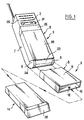
- the terminal comprises a body 1, one front face of which has a earpiece 2 in the vicinity of one of its ends.
- the body 1 is articulated to a pallet foldable 3 movable by pivoting about an axis 4 between the extended position shown in Figure 2 and the position folded shown in Figure 3.
- the pivot means comprise for example two cheeks 6 secured to the body 1 (Figure 1) which is articulated a pin 7 secured to a base 8 of the pallet 3 ( Figures 2 and 3).
- a front face 9 of the base 8 is located opposite the mouth of the user communicating.
- the face 9 then returns the sound of the voice to a microphone 11 located on the front face of the body 1 between the axis 4 and the earpiece 2.
- the sound path is illustrated by the arrow 12.
- the terminal also includes an accumulator block removable 14 which, according to the invention, is part integral with the pallet 3 when it is in the assembled state.
- the base 8 is produced in the form of a flat rectangular tube, open on a front face of its periphery on the side opposite axis 4 and closed on the side of the axis 4.
- the accumulator block 14 fits in the manner of a drawer in the parallelepiped housing 16 defined by this tube.
- a boss 17 of block 14 engages in a corresponding recess 18 of the inner wall of the base 3 for performing a removable locking.
- Block 14 contains a storage battery rechargeable with Cadmium / Nickel, or preferably a storage battery of the type known as Nickel-Metal-Hydrogen Ni (M) H, or even more preferably of the type known as rechargeable lithium. This order preferably corresponds to the order of increasing compactness.
- Block 14 has on its front face, relative to the direction of engagement, at least two rigid contacts 19 which, when the block 14 is locked in the base 8, are in support on two elastic contacts 21 arranged at the bottom of the housing 16.
- the two contacts 21 are connected by a cable flexible 22 with electronics located inside the body 1.
- the cable 22 is preferably of the flat copper type.
- the cable 22 can for example run between the pin 7 and a tongue in the form of a cylindrical sector 23 also integral with the base 8.
- the tongue 23 is coaxial with pin 7 and surrounds it at a certain radial distance.
- the housing 1 has on its rear face a lip 24 ensuring a certain seal with the tongue 23 whatever the angular position of the base 8 around the axis 4 relative to the housing 1, and in particular in its two extreme positions.
- Block 14 has at its end opposite the contacts rigid 9 a gripping region 26 which remains apparent at the exterior of the housing 16 when the block 14 is in position on duty.
- the front face of the body 1 present in the region which is covered by the pallet 3 in the folded position, a recess 27 of sufficient depth to accommodate the thickness of the folded pallet, so that one side rear 28 of the pallet 8 is substantially in the extension of the undocked part 29 of the front face 1 when the pallet is folded.
- this region 29 comprises in addition to the earpiece 2, a display screen 31 allowing the user to perceive certain information even when the palette 8 is folded while the terminal is operating on standby.
- the accumulator block itself constitutes the palette and defines in particular the surface of sound reflection towards the microphone.
- the base is no more than a short frame articulated to the body. We can even completely remove the base, the block then comprising snap-on articulation means on complementary means carried by the body 1, with a system of rotating contacts in this joint.
Landscapes
- Engineering & Computer Science (AREA)
- Signal Processing (AREA)
- Telephone Set Structure (AREA)
- Telephone Function (AREA)
- Burglar Alarm Systems (AREA)
- Transceivers (AREA)
- Fittings On The Vehicle Exterior For Carrying Loads, And Devices For Holding Or Mounting Articles (AREA)
Description
- le document FR-A-2 601 711, qui décrit un terminal portatif repliable, formé de deux boítiers, ou coffrets, renfermant chacun un certain nombre de composants constitutifs de ce terminal. L'un de ces boítiers renferme en particulier un écouteur et une source autonome d'énergie électrique. L'autre de ces boítiers renferme en particulier un microphone.
- le document WO 91 14 332 qui décrit un terminal portatif repliable, comportant un terminal radiotéléphonique, et un récepteur d'appels (ou terminal de radiomessagerie), détachable du terminal radiotéléphonique. Le terminal radiotéléphonique est lui-même formé d'une part d'un corps principal, contenant en particulier une source d'énergie, et d'autre part d'une partie articulée contenant en particulier un microphone. Sur cette partie articulée peut venir se connecter le récepteur d'appels.
- le document US-A-5 027 394 qui décrit également un terminal portatif repliable, formé de deux boítiers, renfermant chacun un certain nombre de composants constitutifs de ce terminal. L'un de ces boítiers renferme en particulier un écouteur. L'autre de ces boítiers renferme en particulier un microphone. Une source d'énergie est par ailleurs prévue dans la partie servant d'articulation entre les deux boítiers.
- le document AU-B-8 367 691 qui décrit également un terminal radiotéléphonique portatif repliable formé de deux segments plats, renfermant chacun un certain nombre de composants constitutifs de ce terminal. L'un de ces segments plats renferme en particulier un écouteur. L'autre de ces segments plats renferme en particulier un microphone, et un bloc accumulateur amovible.
- le document Patent abstracts of Japan, vol.17, n°137 (E-1335) qui décrit également un terminal radiotéléphonique portatif repliable formé de deux éléments, renfermant chacun un certain nombre de composants constitutifs de ce terminal. L'un de ces éléments renferme en particulier un micrcrophone et une batterie. L'autre de ces éléments renferme en particulier un écouteur.
- la figure 1 est une vue d'un terminal en position repliée, avec en outre une représentation partielle d'un socle d'une palette à l'état déployé, et représentation d'un bloc accumulateur destiné à s'y insérer ;
- la figure 2 est une vue partielle du terminal, partiellement en coupe, avec le bloc accumulateur prêt à s'insérer dans le socle de la palette déployée ; et
- la figure 3 est une vue analogue à la figure 2 mais avec la palette repliée et le bloc accumulateur en place.
Claims (4)
- Terminal radiotéléphonique portatif, comprenant un corps (1), un bloc accumulateur (14) amovible, et une palette (3),cette palette (3) étant articulée au corps (1) du terminal entre une position de service dans laquelle elle se trouve devant la bouche de l'utilisateur et une position rabattue sur le corps (1), caractérisé en ce que cette palette constitue un réflecteur destiné à renvoyer le son vers un microphone,et en ce que le bloc accumulateur (14) constitue en lui-même ladite palette (3).
- Terminal selon la revendication 1, caractérisé en ce que la palette (3) comporte une courte monture articulée au corps.
- Terminal selon la revendication 1, caractérisé en ce que le bloc accumulateur comporte des moyens d'articulation encliquetables sur des moyens complémentaires portés par le corps (1), avec un système de contacts tournants dans cette articulation.
- Terminal selon l'une des revendications 1 à 3, caractérisé en ce que le bloc accumulateur (14) est choisi parmi les accumulateurs du type à Nickel-Métal-Hydrogène et les accumulateurs du type à Lithium rechargeable.
Applications Claiming Priority (2)
| Application Number | Priority Date | Filing Date | Title |
|---|---|---|---|
| FR9303315 | 1993-03-23 | ||
| FR9303315A FR2703203B1 (fr) | 1993-03-23 | 1993-03-23 | Terminal radiotéléphonique portatif compact. |
Publications (2)
| Publication Number | Publication Date |
|---|---|
| EP0617536A1 EP0617536A1 (fr) | 1994-09-28 |
| EP0617536B1 true EP0617536B1 (fr) | 2001-05-16 |
Family
ID=9445244
Family Applications (1)
| Application Number | Title | Priority Date | Filing Date |
|---|---|---|---|
| EP94400621A Expired - Lifetime EP0617536B1 (fr) | 1993-03-23 | 1994-03-23 | Terminal radiotéléphonique portatif compact |
Country Status (7)
| Country | Link |
|---|---|
| US (1) | US6665550B1 (fr) |
| EP (1) | EP0617536B1 (fr) |
| AT (1) | ATE201297T1 (fr) |
| AU (1) | AU679478B2 (fr) |
| DE (1) | DE69427204T2 (fr) |
| DK (1) | DK0617536T3 (fr) |
| FR (1) | FR2703203B1 (fr) |
Families Citing this family (17)
| Publication number | Priority date | Publication date | Assignee | Title |
|---|---|---|---|---|
| US5857148A (en) * | 1995-06-13 | 1999-01-05 | Motorola, Inc. | Portable electronic device and method for coupling power thereto |
| US5748757A (en) * | 1995-12-27 | 1998-05-05 | Lucent Technologies Inc. | Collapsible image derived differential microphone |
| KR20010086781A (ko) * | 2000-03-03 | 2001-09-15 | 임성묵 | 솔라셀이 부착된 이동단말기 |
| US6775129B1 (en) * | 2003-02-14 | 2004-08-10 | Intel Corporation | Convertible and detachable laptops |
| GB2401727A (en) * | 2003-05-16 | 2004-11-17 | Inquam | Electronic device with battery slot |
| USD509494S1 (en) * | 2003-10-31 | 2005-09-13 | Samsung Electronics Co., Ltd. | Cellular phone |
| USD522987S1 (en) * | 2003-11-13 | 2006-06-13 | Vodafone K.K. | Cell phone |
| USD515056S1 (en) * | 2003-11-13 | 2006-02-14 | Vodafone K.K. | Cell phone |
| USD524273S1 (en) * | 2003-11-13 | 2006-07-04 | Vodafone K.K. | Cell phone |
| USD515057S1 (en) * | 2003-11-13 | 2006-02-14 | Vodafone K.K. | Cell phone |
| US7483727B2 (en) * | 2005-04-04 | 2009-01-27 | Research In Motion Limited | Mobile wireless communications device having improved antenna impedance match and antenna gain from RF energy |
| KR101366219B1 (ko) * | 2008-09-09 | 2014-02-21 | 제로 크로마, 엘엘씨 | 지지대를 가진 전자 장치의 홀더 |
| US8960634B2 (en) | 2008-09-09 | 2015-02-24 | Zero Chroma, LLC | Holder for electronic device with support |
| US8382059B2 (en) * | 2008-09-09 | 2013-02-26 | Zero Chroma, LLC | Holder for electronic device with support |
| US20100151911A1 (en) | 2008-11-26 | 2010-06-17 | Anthony W. Mazzeo | Integrated telecommunications handset |
| USD612823S1 (en) * | 2008-11-26 | 2010-03-30 | Anthony W. Mazzeo | Handset |
| USD698543S1 (en) | 2012-10-19 | 2014-02-04 | Zerochroma, LLC | Portion of holder for electronic device |
Family Cites Families (17)
| Publication number | Priority date | Publication date | Assignee | Title |
|---|---|---|---|---|
| US4845772A (en) * | 1988-06-13 | 1989-07-04 | Motorola, Inc. | Portable radiotelephone with control switch disabling |
| FR2601211B3 (fr) * | 1986-07-04 | 1988-10-21 | Mecelec Sa | Combine telephonique portable pour systemes de communications du type public |
| ES2041704T3 (es) * | 1987-01-23 | 1993-12-01 | Siemens Aktiengesellschaft | Cuerpo de aparato telefonico manual con una tapa que cierra la instalacion de manejo. |
| JPS6425027A (en) | 1987-07-21 | 1989-01-27 | Asahi Glass Co Ltd | Measuring method of amount of eccentricity between core and clad of optical fiber and direction of eccentricity |
| JPS6489845A (en) * | 1987-09-30 | 1989-04-05 | Matsushita Electric Industrial Co Ltd | Electric appliance |
| WO1991014332A1 (fr) * | 1990-03-05 | 1991-09-19 | Motorola, Inc. | Radio-telephone a capacite de charge secondaire |
| DE69105221T2 (de) * | 1990-03-07 | 1995-06-08 | Sony Corp | Funktelefonapparat. |
| JPH04117849A (ja) * | 1990-09-07 | 1992-04-17 | Fujitsu Ltd | カード式電話機 |
| US5278993A (en) | 1991-02-01 | 1994-01-11 | Motorola, Inc. | Integral spring loaded hinge and switch for portable radio device |
| US5117073A (en) * | 1991-04-02 | 1992-05-26 | Motorola, Inc. | Control signal initiator responsive to a hinge position |
| JPH04307841A (ja) * | 1991-04-05 | 1992-10-30 | Hitachi Ltd | 携帯電話 |
| JPH05153216A (ja) | 1991-11-25 | 1993-06-18 | Sanyo Electric Co Ltd | 携帯用機器 |
| US5335276A (en) * | 1992-12-16 | 1994-08-02 | Texas Instruments Incorporated | Communication system and methods for enhanced information transfer |
| US5548824A (en) * | 1993-08-25 | 1996-08-20 | Mitsubishi Denki Kabushiki Kaisha | Portable radio communication device housing having a battery storage unit |
| US5517683A (en) * | 1995-01-18 | 1996-05-14 | Cycomm Corporation | Conformant compact portable cellular phone case system and connector |
| US5832079A (en) * | 1996-05-03 | 1998-11-03 | Ericsson Inc. | Acoustic horn for use in cellular flip phones |
| US5915015A (en) * | 1996-09-10 | 1999-06-22 | Ericsson, Inc. | Telephone having sealed acoustical passageway through flip cover hinge |
-
1993
- 1993-03-23 FR FR9303315A patent/FR2703203B1/fr not_active Expired - Fee Related
-
1994
- 1994-03-18 AU AU57913/94A patent/AU679478B2/en not_active Ceased
- 1994-03-23 DK DK94400621T patent/DK0617536T3/da active
- 1994-03-23 AT AT94400621T patent/ATE201297T1/de not_active IP Right Cessation
- 1994-03-23 EP EP94400621A patent/EP0617536B1/fr not_active Expired - Lifetime
- 1994-03-23 DE DE69427204T patent/DE69427204T2/de not_active Expired - Lifetime
-
1998
- 1998-01-05 US US09/002,950 patent/US6665550B1/en not_active Expired - Lifetime
Also Published As
| Publication number | Publication date |
|---|---|
| DE69427204T2 (de) | 2002-01-03 |
| DE69427204D1 (de) | 2001-06-21 |
| FR2703203A1 (fr) | 1994-09-30 |
| ATE201297T1 (de) | 2001-06-15 |
| DK0617536T3 (da) | 2001-08-27 |
| US6665550B1 (en) | 2003-12-16 |
| AU679478B2 (en) | 1997-07-03 |
| EP0617536A1 (fr) | 1994-09-28 |
| FR2703203B1 (fr) | 1995-04-28 |
| AU5791394A (en) | 1994-09-29 |
Similar Documents
| Publication | Publication Date | Title |
|---|---|---|
| EP0617536B1 (fr) | Terminal radiotéléphonique portatif compact | |
| US8611578B2 (en) | Charging cradle for a headset device and an earphone cover for the headset device | |
| FR2783663A1 (fr) | Dispositif pour une utilisation sans risque d'un telephone cellulaire portable tout en conduisant | |
| EP0890248A1 (fr) | Combine telephonique transformable en casque telephonique | |
| FR2675327A1 (fr) | Mecanisme de charniere pour radiotelephone repliable. | |
| EP3333870B1 (fr) | Commutateur électrique | |
| FR2758671A1 (fr) | Telephone cellulaire repliable en trois parties | |
| EP0971520A1 (fr) | Appareil électronique portable, son boítier et son magasin de batterie | |
| EP1039726A1 (fr) | Téléphone portable avec volet articulé par rapport au boítier | |
| FR2806863A1 (fr) | Appareil electrique portatif contenant une batterie d'accumulateurs | |
| FR2909167A1 (fr) | Dispositif de nivellement laser | |
| FR2839393A1 (fr) | Agencement d'un element femelle et dispositif mobile. | |
| FR2709032A1 (fr) | Système de verrouillage. | |
| EP0858172B1 (fr) | Bloc d'alimentation d'un dispositif portatif, du type permettant l'utilisation de différents types d'alimentation, et dispositif portatif correspondant | |
| EP0504864A1 (fr) | Appareil téléphonique comportant un premier et un second combiné | |
| EP0575214B1 (fr) | Appareil électronique transformable pour montage mural ou en baie | |
| EP4078641A1 (fr) | Mecanisme pour un commutateur electrique,ensemble electrique et commutateur electrique associes | |
| EP1978607A1 (fr) | Chargeur électrique muni d'un plot de connexion articulé | |
| EP3840003B1 (fr) | Enjoliveur et commutateur électrique comprenant un tel enjoliveur | |
| EP4356806A1 (fr) | Conduit d'aspirateur équipé d'un dispositif d'articulation | |
| FR2624714A1 (fr) | Aspirateur manuel de poussieres, notamment de petit modele | |
| EP0933907A1 (fr) | Appareil téléphonique mobile à écoute amplifiée | |
| FR2821975A1 (fr) | Dispositif de pivotement a trois positions d'un volet pour radiothelephone | |
| EP2012504A1 (fr) | Dispositif portable de communication téléphonique sans fil, tel qu'une oreillette, muni d'un connecteur rétractable | |
| FR2826819A1 (fr) | Support destine a un telephone portable |
Legal Events
| Date | Code | Title | Description |
|---|---|---|---|
| PUAI | Public reference made under article 153(3) epc to a published international application that has entered the european phase |
Free format text: ORIGINAL CODE: 0009012 |
|
| AK | Designated contracting states |
Kind code of ref document: A1 Designated state(s): AT BE DE DK ES FR GB IT NL SE |
|
| RAP1 | Party data changed (applicant data changed or rights of an application transferred) |
Owner name: ALCATEL MOBILE COMMUNICATION FRANCE |
|
| 17P | Request for examination filed |
Effective date: 19950202 |
|
| 17Q | First examination report despatched |
Effective date: 19970905 |
|
| RIC1 | Information provided on ipc code assigned before grant |
Free format text: 7H 04M 1/02 A |
|
| GRAG | Despatch of communication of intention to grant |
Free format text: ORIGINAL CODE: EPIDOS AGRA |
|
| GRAG | Despatch of communication of intention to grant |
Free format text: ORIGINAL CODE: EPIDOS AGRA |
|
| GRAH | Despatch of communication of intention to grant a patent |
Free format text: ORIGINAL CODE: EPIDOS IGRA |
|
| GRAH | Despatch of communication of intention to grant a patent |
Free format text: ORIGINAL CODE: EPIDOS IGRA |
|
| GRAA | (expected) grant |
Free format text: ORIGINAL CODE: 0009210 |
|
| RAP1 | Party data changed (applicant data changed or rights of an application transferred) |
Owner name: ALCATEL |
|
| AK | Designated contracting states |
Kind code of ref document: B1 Designated state(s): AT BE DE DK ES FR GB IT NL SE |
|
| PG25 | Lapsed in a contracting state [announced via postgrant information from national office to epo] |
Ref country code: IT Free format text: LAPSE BECAUSE OF FAILURE TO SUBMIT A TRANSLATION OF THE DESCRIPTION OR TO PAY THE FEE WITHIN THE PRESCRIBED TIME-LIMIT;WARNING: LAPSES OF ITALIAN PATENTS WITH EFFECTIVE DATE BEFORE 2007 MAY HAVE OCCURRED AT ANY TIME BEFORE 2007. THE CORRECT EFFECTIVE DATE MAY BE DIFFERENT FROM THE ONE RECORDED. Effective date: 20010516 |
|
| REF | Corresponds to: |
Ref document number: 201297 Country of ref document: AT Date of ref document: 20010615 Kind code of ref document: T |
|
| GBT | Gb: translation of ep patent filed (gb section 77(6)(a)/1977) |
Effective date: 20010517 |
|
| REF | Corresponds to: |
Ref document number: 69427204 Country of ref document: DE Date of ref document: 20010621 |
|
| PG25 | Lapsed in a contracting state [announced via postgrant information from national office to epo] |
Ref country code: SE Free format text: LAPSE BECAUSE OF FAILURE TO SUBMIT A TRANSLATION OF THE DESCRIPTION OR TO PAY THE FEE WITHIN THE PRESCRIBED TIME-LIMIT Effective date: 20010816 |
|
| REG | Reference to a national code |
Ref country code: DK Ref legal event code: T3 |
|
| PG25 | Lapsed in a contracting state [announced via postgrant information from national office to epo] |
Ref country code: ES Free format text: LAPSE BECAUSE OF FAILURE TO SUBMIT A TRANSLATION OF THE DESCRIPTION OR TO PAY THE FEE WITHIN THE PRESCRIBED TIME-LIMIT Effective date: 20011130 |
|
| REG | Reference to a national code |
Ref country code: GB Ref legal event code: IF02 |
|
| PGFP | Annual fee paid to national office [announced via postgrant information from national office to epo] |
Ref country code: NL Payment date: 20020228 Year of fee payment: 9 |
|
| PGFP | Annual fee paid to national office [announced via postgrant information from national office to epo] |
Ref country code: DK Payment date: 20020304 Year of fee payment: 9 |
|
| PLBE | No opposition filed within time limit |
Free format text: ORIGINAL CODE: 0009261 |
|
| STAA | Information on the status of an ep patent application or granted ep patent |
Free format text: STATUS: NO OPPOSITION FILED WITHIN TIME LIMIT |
|
| PG25 | Lapsed in a contracting state [announced via postgrant information from national office to epo] |
Ref country code: AT Free format text: LAPSE BECAUSE OF FAILURE TO SUBMIT A TRANSLATION OF THE DESCRIPTION OR TO PAY THE FEE WITHIN THE PRESCRIBED TIME-LIMIT Effective date: 20020323 |
|
| PG25 | Lapsed in a contracting state [announced via postgrant information from national office to epo] |
Ref country code: BE Free format text: LAPSE BECAUSE OF NON-PAYMENT OF DUE FEES Effective date: 20020331 |
|
| 26N | No opposition filed | ||
| BERE | Be: lapsed |
Owner name: *ALCATEL Effective date: 20020331 |
|
| PG25 | Lapsed in a contracting state [announced via postgrant information from national office to epo] |
Ref country code: DK Free format text: LAPSE BECAUSE OF NON-PAYMENT OF DUE FEES Effective date: 20030331 |
|
| PG25 | Lapsed in a contracting state [announced via postgrant information from national office to epo] |
Ref country code: NL Free format text: LAPSE BECAUSE OF NON-PAYMENT OF DUE FEES Effective date: 20031001 |
|
| NLV4 | Nl: lapsed or anulled due to non-payment of the annual fee |
Effective date: 20031001 |
|
| REG | Reference to a national code |
Ref country code: FR Ref legal event code: TP |
|
| REG | Reference to a national code |
Ref country code: GB Ref legal event code: 732E |
|
| REG | Reference to a national code |
Ref country code: GB Ref legal event code: 732E Free format text: REGISTERED BETWEEN 20090924 AND 20090930 |
|
| REG | Reference to a national code |
Ref country code: GB Ref legal event code: 732E Free format text: REGISTERED BETWEEN 20120607 AND 20120613 |
|
| REG | Reference to a national code |
Ref country code: FR Ref legal event code: TP Owner name: Z124, GB Effective date: 20130201 Ref country code: FR Ref legal event code: CD Owner name: Z124, GB Effective date: 20130201 |
|
| PGFP | Annual fee paid to national office [announced via postgrant information from national office to epo] |
Ref country code: DE Payment date: 20130320 Year of fee payment: 20 Ref country code: GB Payment date: 20130320 Year of fee payment: 20 Ref country code: FR Payment date: 20130408 Year of fee payment: 20 |
|
| REG | Reference to a national code |
Ref country code: DE Ref legal event code: R071 Ref document number: 69427204 Country of ref document: DE |
|
| REG | Reference to a national code |
Ref country code: DE Ref legal event code: R071 Ref document number: 69427204 Country of ref document: DE |
|
| REG | Reference to a national code |
Ref country code: GB Ref legal event code: PE20 Expiry date: 20140322 |
|
| PG25 | Lapsed in a contracting state [announced via postgrant information from national office to epo] |
Ref country code: DE Free format text: LAPSE BECAUSE OF EXPIRATION OF PROTECTION Effective date: 20140325 Ref country code: GB Free format text: LAPSE BECAUSE OF EXPIRATION OF PROTECTION Effective date: 20140322 |