EP0615901A1 - Flugzeugfahrwerk mit seitlichem Einfahren - Google Patents
Flugzeugfahrwerk mit seitlichem Einfahren Download PDFInfo
- Publication number
- EP0615901A1 EP0615901A1 EP94400440A EP94400440A EP0615901A1 EP 0615901 A1 EP0615901 A1 EP 0615901A1 EP 94400440 A EP94400440 A EP 94400440A EP 94400440 A EP94400440 A EP 94400440A EP 0615901 A1 EP0615901 A1 EP 0615901A1
- Authority
- EP
- European Patent Office
- Prior art keywords
- articulated
- balance
- landing gear
- pivoting
- train
- Prior art date
- Legal status (The legal status is an assumption and is not a legal conclusion. Google has not performed a legal analysis and makes no representation as to the accuracy of the status listed.)
- Withdrawn
Links
Images


Classifications
-
- B—PERFORMING OPERATIONS; TRANSPORTING
- B64—AIRCRAFT; AVIATION; COSMONAUTICS
- B64C—AEROPLANES; HELICOPTERS
- B64C25/00—Alighting gear
- B64C25/32—Alighting gear characterised by elements which contact the ground or similar surface
- B64C25/34—Alighting gear characterised by elements which contact the ground or similar surface wheeled type, e.g. multi-wheeled bogies
-
- B—PERFORMING OPERATIONS; TRANSPORTING
- B64—AIRCRAFT; AVIATION; COSMONAUTICS
- B64C—AEROPLANES; HELICOPTERS
- B64C25/00—Alighting gear
- B64C25/02—Undercarriages
- B64C25/08—Undercarriages non-fixed, e.g. jettisonable
- B64C25/10—Undercarriages non-fixed, e.g. jettisonable retractable, foldable, or the like
- B64C25/12—Undercarriages non-fixed, e.g. jettisonable retractable, foldable, or the like sideways
- B64C2025/125—Undercarriages non-fixed, e.g. jettisonable retractable, foldable, or the like sideways into the fuselage, e.g. main landing gear pivotally retracting into or extending out of the fuselage
Definitions
- the invention relates to aircraft landing gears, of the side-lift type, and more particularly to a train comprising a leg articulated on an aircraft structure and equipped below with a set of wheels, and an operating jack ensuring the pivoting of this leg around its axis.
- the positions of the frames of the aircraft structure coincide with the necessary position of the undercarriages for a desirable distribution of the loads, with respect to the center of gravity of the aircraft, between the front undercarriage and the main undercarriages.
- the axis of the wheels of the main undercarriages can in particular be offset towards the rear of the structural frames, which implies advancing the wheel or wheels in the process of lifting the train.
- Landing gear legs are used, for example, constituted by a rigid box articulated on the aircraft structure, and by a wheel-bearing balance articulated at the end of this box.
- a generally inclined longitudinal axis is used as the pivot axis of the box.
- the trajectory is then constraining, in particular when the offset is significant between the structure of the aircraft and the undercarriage wheels in the low gear position, and, if the compactness of the housing is primarily sought, has a risk of having to adapt the lower part of the structure of the aircraft, for example by releasing lower parts of the frames delimiting this housing.
- the object of the invention is precisely to solve this problem, by designing a landing gear which does not have the aforementioned drawbacks and / or limitations, having regard to the structural complexity of the train and the constraints affecting the structure of the aircraft for the re-entry of this train and its housing in the high train position.
- the object of the invention is therefore to produce a landing gear of the side-lift type, the structure of which makes it possible to optimize the kinematics of the moving components to pass from one position to the other of said train while conforming to a trajectory. optimal with regard to the particular geometry of the aircraft, while facilitating the control of this trajectory during lifting or lowering movements of the train, so as to be able to use a housing of optimal compactness in the longitudinal direction without risk of disturbance during approaching the wheels.
- the combined use of the two pivot axes and of the pendulum pivot control means provides an optimal definition of the trajectory and excellent control of this trajectory, without any noticeable complication of the structure of the landing gear.
- the rigid box is articulated on the aircraft structure by being able to rotate about an axis which is substantially parallel to the central axis of the aircraft, which simplifies the arrangement of the structure of the aircraft.
- the means for controlling the pivoting of the balance consists of an articulated system mounted on the rigid box, this system comprising a triangulation on which the shock absorber is hung and a connecting member articulated on the structure aircraft, being arranged to push (respectively pull) on this shock absorber during lifting (respectively descent) of the train.
- the articulated system could include a lever articulated on the rigid box, said lever comprising a first arm which defines, with a connecting rod connecting this arm to the point of attachment of the shock absorber, a locking alignment in low gear position, and a second arm which is directly attacked by the link member articulated on the aircraft structure.
- the connecting member may be produced in the form of a connecting rod or a hydraulic cylinder.
- the means for controlling the pivoting of the balance consists of a cam articulated on the rigid box, with which a roller mounted on an appendage of the balance cooperates, and by a connecting member connecting this articulated cam to the aircraft structure, said cam including a stop against which said roller is held in abutment, in the low gear position, by the thrust exerted by the shock absorber on the pendulum, and said connecting member being arranged to retract (respectively replace ) said stop when the train is lifted (respectively lowered).
- the connecting member may be produced in the form of a connecting rod or of a hydraulic cylinder.
- the means for controlling the pivoting of the balance consists of a telescopic connecting rod connecting an appendage of the balance to an arm of a lever which is articulated on an appendage of the rigid box, the other arm of this lever being connected to the aircraft structure via an associated connecting rod.
- the means for controlling the pivoting of the balance consists of a telescopic connecting rod with an integrated system for hydraulic extension or shortening control, connecting an appendage of the balance to an appendage of the rigid box.
- the telescopic connecting rod can also include an oleo-pneumatic emergency system making it possible, in the event of a hydraulic failure, to pivot the balance by the action of an associated internal pusher.
- the means for controlling the pivoting of the balance consists of a hydraulic cylinder integrated in the shock absorber, said shock absorber comprising for this purpose a telescopic rod fitted internally with a piston rod and a locking device associated, which piston rod is hung on an appendage of the pendulum.
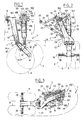
- a landing gear T according to the invention, said train being of the side lift type, and being received in an associated housing L of the aircraft structure concerned , said housing being delimited by two transverse frames C spaced apart from each other by a distance corresponding substantially to the diameter of the wheels R of this landing gear.
- the landing gear T comprises a leg 50 articulated on an aircraft structure S and equipped below with a set of wheels R, an actuating cylinder 20 ensuring the pivoting of this leg around its axis.
- the leg 5O is formed of a rigid box 1O, articulated by its upper portion 1O.1 on the aircraft structure while being able to rotate around an axis 11 is here substantially parallel to the central axis of the aircraft (it goes without saying, however, that the axis 11 may have a slight inclination relative to the median longitudinal plane of the aircraft and / or to a transverse plane), and of a wheel-carrying balance 12 articulated at the end of the box 10 being able to turn around an axis 13 which, in the low gear position, is substantially perpendicular to the median longitudinal plane of the aircraft (in practice, it is arranged to have this perpendicularity under load to limit tire wear).
- the axis 14 of the wheel spindles 26 is here arranged at the end of the balance wheel 12.
- the direction of the aircraft is also shown diagrammatically by the arrow 30.
- the main pivot axes, c ' that is to say the axis 11 of pivoting of the rigid box 10, and the axis 13 of pivoting of the wheel carrying balance 12, are substantially orthogonal.
- bracing means of the traditional type associated with the leg 50 here with an articulated strut comprising an arm 22 articulated on an appendage 24 of the rigid box 10, and an arm 23 articulated at a point 25 on the aircraft structure.
- the strut formed by the arms 22 and 23 can be fitted with any locking and unlocking system of the traditional type, such a system not being illustrated here.
- a damper 15 also connects the rigid box 10 to the oscillating balance 12, this damper being articulated on the balance at a point 17 of an appendage 16 of said balance, which point 17 is located between the articulation axis 13 of this balance and axis 14 of the wheel set R.
- the balance 12 is also directly connected, here by means of the damper 15, to a pivoting control means which is arranged to reduce, when the train is raised, the 'angle A formed by the direction of the rigid box 10 and the direction of the balance 12, so that in the high gear position said balance extends substantially in the extension of said box, and vice versa to increase this angle when lowering said train , by conforming to a predetermined trajectory.
- the means for controlling the pivoting of the balance consists of an articulated system 100 associated with the attachment of the upper part of the shock absorber 15. More precisely, the articulated system 100 comprises a triangulation on which the l shock absorber 15 at level from a point 103, and a connecting member 110 articulated on the aircraft structure at an end point 111 of said member.
- the articulated system 100 comprises a triangulation on which the l shock absorber 15 at level from a point 103, and a connecting member 110 articulated on the aircraft structure at an end point 111 of said member.
- FIG. 2 there is therefore a first connecting rod 101 articulated on a lateral appendage 102 of the rigid box 10, and a second connecting rod 104 articulated coaxially with the first connecting rod 101 at the point of attachment 103 of the shock absorber 15, this second connecting rod 104 being articulated at its other end on a lever 105 itself articulated at 109 on an appendage 106 of the rigid box 10.
- a double appendage 102 forming a yoke on which are articulated two connecting rods 101 connected to two connecting rods 104, arranged symmetrically on either side of this plane.
- a double appendage 106 is also provided, defining a lower yoke, for the articulation of the lever 105 forming part of the articulated system 100.
- the lever 105 comprises a first arm 107 which defines, with the connecting rod 104 connecting this arm to the point of attachment 103 of the shock absorber 15, a locking alignment in the low gear position (position of FIG.
- the connecting member 110 is produced in the form of a rigid connecting rod. As will be seen later, it may prove advantageous to replace this connecting rod with a hydraulic cylinder, as part of a sequential embodiment of the pivoting movements of the landing gear.
- the articulated system 100 thus comprises a triangulation 101, 104, 105 on which the shock absorber 15 is hung, as well as the connecting member 110 articulated on the aircraft structure, and this system is arranged so as to push (respectively pull ) on this shock absorber when raising (respectively descending) the landing gear T.
- the connecting rods 101 and 104 have exerted a thrust on the damper 15, as shown diagrammatically by the arrow 31, which thrust is transmitted directly to the oscillating balance 12, which has the effect of reducing the angle A formed by the direction of the rigid box 10 and the direction of the balance 12.
- the normal low gear position is shown, which is here an intermediate position between the high position of the wheels corresponding to maximum compression of the shock absorber 15, and a low position of the wheels in which the angle A is practically zero, that is to say that the balance 12 extends then in the direct extension (in lateral view according to FIG. 1) of the rigid box 10, this position being reached when the landing gear reaches its final position of reception in the associated housing L, the wheels R then progressing sively advanced during the pivoting of the leg 50, to finally come to pass precisely between the two frames concerned C delimiting the associated housing L. It is therefore possible to have a housing L which is of optimal compactness in the longitudinal direction.
- the articulated system 100 is here exclusively constituted by rigid mechanical elements, so that the kinematics are perfectly defined at all times of the lifting or lowering movement of the train.
- the connecting rods 101 and 104 to which the shock absorber 15 is attached above exert a traction on this shock absorber tending to raise it, which traction has the effect of pivoting the oscillating lever 12 by increasing the angle A associated , and this until the final low gear position is reached.
- the connecting rod 104 and the arm 107 of the lever 105 both define a locking alignment in the low gear position, as illustrated in the Figure 2, this alignment being here locked unfolded.
- the articulated system could be arranged differently, and the variant which will be described below comprises a different arrangement with a locking alignment in the low gear position which is locked folded.
- the connecting rod 110 of the articulated system 100 which has just been described by a hydraulic pivoting cylinder (variant not shown here) , which cylinder must then naturally be hung no longer on the aircraft structure, but on the rigid box.
- FIGS 4 to 6 illustrate a variant which is close to the previous embodiment which has just been described, so that the same references have been kept for the homologous elements.
- the pivoting means of the pendulum, referenced 200 is again constituted by an articulated system mounted on the rigid box 10, this system comprising a triangulation on which the shock absorber 15 is hung, and a connecting member 210 articulated on the structure d 'aircraft, being arranged to push (respectively pull) on this shock absorber during lifting (respectively descent) of the train.
- the articulated system 200 is however arranged differently compared to the articulated system of the previously described variant, as explained below.
- the rigid box 10 has in the upper part a central appendage 202, on which is articulated a connecting rod 201 on the one hand and a lever 205 on the other hand.
- the lever 205 is articulated by being able to rotate about an axis 209, and comprises a first arm 207 connecting to a connecting rod 204, the latter joining the connecting rod 201 at the point of attachment 203 of the shock absorber 15.
- the another arm 208 of the lever 205 is directly attacked by the connecting member 210 articulated on the aircraft structure, which member is in this case produced in the form of a rigid rod. As can be seen in FIG.
- the essential difference lies in a particular structure of the means for controlling the pivoting of the balance, which means is referenced 300.
- the control means 300 is constituted by a cam 320, articulated around an axis 322 carried by an appendage 321 of the rigid box 10, cam with which a roller 329 cooperates mounted at the end of an appendage 328 of the pendulum 12. It is advisable to organize the pivoting of the cam 320 around its axis when the rigid box 10 pivots about its axis 11: in this case, this is ensured by means of a connecting member 325 connecting this articulated cam 320 to the aircraft structure.
- This connecting member 325 is here produced in the form of an elongated rod, articulated at 327 on the articulated cam 320, and at 326 on the aircraft structure.
- the cam 320 has an active profile 324 with which the roller 329 cooperates, this contour including a stop portion 324.1 against which the roller 329 is held in abutment, in the low train position (as illustrated in FIG. 7), by the thrust exerted by the damper 15 on the balance 12.
- the control rod 325 exerts traction on the articulated cam 320, which releases the roller 329 from the associated stop 324.1, and consequently frees the pivoting of the balance 12 around its axis 13.
- the roller 329 remains in contact with this associated cam profile 324, until either reaches the position in which said roller reaches the end of the profile, a position which is illustrated in FIG. 9 and which corresponds to a top view in the top gear position.
- the articulated stop 320 is retracted as a result of the traction exerted on this by the control rod 325, there is release of the rebound of the damper 15 which can rotate the balance 12 in order to advance the wheels R during the pivoting of the leg of the train.
- the stop 324.1 is thus a relaxation stop, and the contact is ensured permanently in the low train position thanks to the thrust reserve provided by the damper 15.
- this arm which is of course in no way obligatory insofar as the roller 329 should in principle not come to contact it, nevertheless constitutes an interesting safety guaranteeing the good trajectory of the roller 329, in particular constituting a safety member additional in case of deflation of the shock absorber 15, because the roller 329 is then trapped at the bottom of the associated lumen.
- the lifting process then includes a preliminary step of disengaging the stop of the articulated cam to release the pivoting of the balance, then we find the stages of pivoting of the balance around its axis 13, and finally the pivoting of the rigid box 10 around its axis 11.
- the essential difference lies in the particular arrangement of the means for controlling the pivoting of the balance 12, which means is here produced in the form of a telescopic rod 400.
- the balance 12 has for this purpose a appendix 430 used for hooking, at point 431, the end of the rod 441 of the telescopic connecting rod.
- the body 440 of the telescopic rod 400 is articulated, at a point 432, on an arm 436 of a lever 433 itself articulated at 434 on an appendage 435 of the rigid box 10, the other arm 437 this lever being in turn connected to the aircraft structure via an associated connecting rod 438 articulated at 439 on the aircraft structure.
- FIG. 12 makes it possible to better distinguish the structure of the telescopic connecting rod 400 used here, and there is in particular a piston 441.1 secured to the rod 441, and the hollow body 440.1 secured to the body 440, in which this piston 441.1 slides, which allows complete protection of the sliding zone of this piston in the associated chamber 442 which is open to the open air.
- the position illustrated in FIG. 12 is a clear stop position, a position in which the mechanical stop members are perfectly protected against external agents.
- the telescopic rod 500 is here directly hooked, at a point 532, to an appendage 543 secured to the portion 10.1 of the rigid box 10, so that the body 540 of this control rod is no longer hung on an articulated lever system as was the case for the previous variant.
- the rod 541 of this connecting rod is as to it is articulated at a point 531 on an appendix 530 of the pendulum 12.
- the ground S has been represented with the pitch angle CA of the airplane during the contact of the wheels R with the ground S. previously, the angle A defined by the direction of the rigid box 10 and that of the oscillating balance 12.
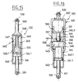
- FIG. 15 shows in section the special control rod 500 which makes it possible to organize the pivoting of the balance 12, in accordance with a sequential embodiment of the two pivoting movements.
- a sliding part with a piston 541.1 moving in a hollow body 540.1, with an associated chamber 542 open to the air.
- organs ensuring the hydraulic control of elongation or shortening of the telescopic rod 500.
- the hollow body 540.1 in fact receives a piston 546 which slides on a fixed inner rod 547 pierced with orifices 548.
- the body 540.1 is further provided with an orifice 544 which can be connected either to a source of hydraulic pressure, or to a hydraulic tank, the corresponding chamber 549 then being occupied by hydraulic fluid.
- the position illustrated in Figure 15 corresponds to the control of maximum elongation, that is to say a movement of descent of the train.
- a sensor will then be used to detect the correct position of the pendulum at the end of pivoting, in order to raise the landing gear leg.
- FIG. 16 illustrates in section a variant of the telescopic connecting rod of FIG. 15, variant in which the connecting rod 500 also includes an oleo-pneumatic emergency system 550 making it possible, in the event of a hydraulic failure, to pivot the balance 12 by the action of an associated internal pusher 553.
- the connecting rod 500 differs from the preceding connecting rod by the presence, beyond an intermediate fixed bottom 558 of a piston 551 sliding in an extension 540.2 of the body of the connecting rod, which piston delimits a hydraulic chamber 555 through which a internal pusher 553 passing through the fixed bottom 558, and a chamber 552 occupied by a high pressure gaseous fluid.
- An orifice 557 is associated with the hydraulic chamber 555, which orifice is connected to a solenoid valve 556 for emergency control.
- the means for controlling the pivoting of the balance consists of a hydraulic cylinder integrated in the shock absorber.
- the shock absorber 15 is then hooked at point 603 directly on the portion 10.1 of the rigid box 10, and the lower part 600 of this shock absorber 15 is articulated at point 17 on the appendix 16 of the balance wheel 12. In in this case, there is no longer an appendage formed in front of this balance 12, which balance is in this case elongated.
- a telescopic rod 661 slides, here in the position of maximum extension by pressing the associated stops 669.
- the piston 662 of the rod 661 has diaphragm openings 663, and the upper part of this rod is guided by a disc 664 carried by a fixed rod 666, which disc also has orifices forming a diaphragm 665, so that the fluid chamber 668 communicates with the upper part of the damper, the fluid surface being in direct contact with a gaseous fluid 667, in accordance with an embodiment well known in the field of shock absorbers.
- the telescopic rod 661 also has an intermediate fixed bottom 672 below which there is a hydraulic cylinder with a rod 670 sliding in the telescopic rod 661.
- the piston of this rod 670 slides in a chamber 671 and, in the high position of this rod 670 (position illustrated in FIG. 18), said rod is retained by a claw locking system 673 held by a pusher 674 subjected to the action of a thrust spring 675, said pusher being hollow to allow the hydraulic fluid entering the rod 670 to pass through a lateral orifice 676 and a conduit axial 677.
- the chamber 671 is further provided with a fluid orifice 678.
- the pressurized fluid is supplied through the orifice 676 of the rod 670, which has the effect of pushing the pusher 674 down against the action of the associated spring 675, and of unlocking the system to claws 673, which authorizes the exit of the internal telescopic rod 670 (the orifice 678 being put on the cover), and consequently the pivoting of the pendulum 12.
- the closure is controlled orifice 676, or a pressure maintenance, in order to have a locking in position by the hydraulic fluid.
- the normal lifting is then carried out by actuating the operating cylinder 20, the damper 15 then behaving like a monolithic assembly.
- the procedure is the opposite, first actuating the operating cylinder 20, then, when the low position of the rigid box can be detected (for example by means of a sensor associated with the counter locking plug in the bottom gear position), pressure fluid is then admitted at the level of the orifice 678, the orifice 676 then being connected to the cover, which causes the retracting of the telescopic inner rod 670, up to when it is locked by the claw system 673, the fluid supply being stopped when the lock has been detected.
- the raising of the telescopic rod 670 thus produces the desired pivoting movement of the balance 12, until the final position of the train is obtained.
Applications Claiming Priority (2)
| Application Number | Priority Date | Filing Date | Title |
|---|---|---|---|
| FR9302946A FR2702732B1 (fr) | 1993-03-15 | 1993-03-15 | Train d'atterrissage d'aeronef, du type a relevage lateral. |
| FR9302946 | 1993-03-15 |
Publications (1)
| Publication Number | Publication Date |
|---|---|
| EP0615901A1 true EP0615901A1 (de) | 1994-09-21 |
Family
ID=9444953
Family Applications (1)
| Application Number | Title | Priority Date | Filing Date |
|---|---|---|---|
| EP94400440A Withdrawn EP0615901A1 (de) | 1993-03-15 | 1994-03-02 | Flugzeugfahrwerk mit seitlichem Einfahren |
Country Status (2)
| Country | Link |
|---|---|
| EP (1) | EP0615901A1 (de) |
| FR (1) | FR2702732B1 (de) |
Cited By (6)
| Publication number | Priority date | Publication date | Assignee | Title |
|---|---|---|---|---|
| US5584336A (en) * | 1993-10-07 | 1996-12-17 | Norandal, Usa | Thin gauge roll casting method |
| GB2472988A (en) * | 2009-08-25 | 2011-03-02 | Messier Dowty Ltd | Main landing gear with rigid rear stay |
| CN112224389A (zh) * | 2020-10-09 | 2021-01-15 | 南京航空航天大学 | 一种可适应不同规格及布局要求的可收放主起落架 |
| CN112623204A (zh) * | 2021-02-18 | 2021-04-09 | 江西洪都航空工业集团有限责任公司 | 一种新型起落架回中机构 |
| CN112644692A (zh) * | 2020-12-29 | 2021-04-13 | 中国航空工业集团公司西安飞机设计研究所 | 一种飞机起落架放下位置锁定装置 |
| CN114180036A (zh) * | 2021-11-19 | 2022-03-15 | 中国直升机设计研究所 | 一种直升机用一体化收放起落架 |
Families Citing this family (2)
| Publication number | Priority date | Publication date | Assignee | Title |
|---|---|---|---|---|
| FR2725178B1 (fr) | 1994-10-04 | 1996-10-25 | Messier Eram | Train d'atterrissage d'aeronef, du type a relevage lateral |
| FR3132695A1 (fr) | 2022-02-17 | 2023-08-18 | Safran Landing Systems | Atterrisseur à longueur variable et aéronef équipé d’un tel atterrisseur |
Citations (2)
| Publication number | Priority date | Publication date | Assignee | Title |
|---|---|---|---|---|
| GB911121A (en) * | 1959-02-05 | 1962-11-21 | English Electric Co Ltd | Improvements in and relating to aircraft undercarriages |
| DE1272736B (de) * | 1966-08-24 | 1968-07-11 | Dornier Gmbh | Um eine sich in Flugzeuglaengsrichtung erstreckende Achse einschwenkbares Flugzeugfahrwerk |
-
1993
- 1993-03-15 FR FR9302946A patent/FR2702732B1/fr not_active Expired - Fee Related
-
1994
- 1994-03-02 EP EP94400440A patent/EP0615901A1/de not_active Withdrawn
Patent Citations (2)
| Publication number | Priority date | Publication date | Assignee | Title |
|---|---|---|---|---|
| GB911121A (en) * | 1959-02-05 | 1962-11-21 | English Electric Co Ltd | Improvements in and relating to aircraft undercarriages |
| DE1272736B (de) * | 1966-08-24 | 1968-07-11 | Dornier Gmbh | Um eine sich in Flugzeuglaengsrichtung erstreckende Achse einschwenkbares Flugzeugfahrwerk |
Cited By (9)
| Publication number | Priority date | Publication date | Assignee | Title |
|---|---|---|---|---|
| US5584336A (en) * | 1993-10-07 | 1996-12-17 | Norandal, Usa | Thin gauge roll casting method |
| GB2472988A (en) * | 2009-08-25 | 2011-03-02 | Messier Dowty Ltd | Main landing gear with rigid rear stay |
| US8844864B2 (en) | 2009-08-25 | 2014-09-30 | Messier-Dowty Limited | Main landing gear with rigid rear stay |
| CN112224389A (zh) * | 2020-10-09 | 2021-01-15 | 南京航空航天大学 | 一种可适应不同规格及布局要求的可收放主起落架 |
| CN112644692A (zh) * | 2020-12-29 | 2021-04-13 | 中国航空工业集团公司西安飞机设计研究所 | 一种飞机起落架放下位置锁定装置 |
| CN112623204A (zh) * | 2021-02-18 | 2021-04-09 | 江西洪都航空工业集团有限责任公司 | 一种新型起落架回中机构 |
| CN112623204B (zh) * | 2021-02-18 | 2023-03-10 | 江西洪都航空工业集团有限责任公司 | 一种起落架回中机构 |
| CN114180036A (zh) * | 2021-11-19 | 2022-03-15 | 中国直升机设计研究所 | 一种直升机用一体化收放起落架 |
| CN114180036B (zh) * | 2021-11-19 | 2023-04-18 | 中国直升机设计研究所 | 一种直升机用一体化收放起落架 |
Also Published As
| Publication number | Publication date |
|---|---|
| FR2702732B1 (fr) | 1995-06-09 |
| FR2702732A1 (fr) | 1994-09-23 |
Similar Documents
| Publication | Publication Date | Title |
|---|---|---|
| FR2688467A1 (fr) | Atterrisseur relevable a raccourcissement de jambe. | |
| EP0564325A1 (de) | Einziehfahrwerk, insbesondere für Hubschrauber | |
| CA3031825C (fr) | Atterrisseur a contrefiche a lumiere | |
| CA2767857C (fr) | Train avant d'aeronef a dispositif de commande unique pour le relevage et la direction | |
| CA1230869A (fr) | Atterrisseur pour aeronef | |
| EP0176442A1 (de) | Verlängerbare Anhängerkupplung für Strassenfahrzeuge und Schienenfahrzeuge | |
| FR2616410A1 (fr) | Dispositif d'atterrissage a poutre basculante | |
| EP0614804A1 (de) | Einziehfahrwerk eines Grossraumflugzeuges | |
| EP0615901A1 (de) | Flugzeugfahrwerk mit seitlichem Einfahren | |
| EP1581424B1 (de) | Fahrwerk-federbeindämpfer und diesen enthaltendes fahrwerk mit unabhängigen federbeinen | |
| EP0288377B1 (de) | Landungssystem eines Flugzeuges | |
| FR2501153A1 (fr) | Train d'atterrissage de fuselage a roues en tandem | |
| FR2688190A1 (fr) | Train d'atterrissage relevable. | |
| EP0062564B1 (de) | Tandem-Fahrgestell | |
| FR2687123A1 (fr) | Train d'atterrissage relevable d'aeronef, notamment pour helicoptere. | |
| EP0013202B1 (de) | Seitlich einziehbares Flugzeughauptfahrwerk mit einer Balancierstange | |
| EP0676328A2 (de) | Einziehfahrwerk mit vertikaler Bewegung für ein Grossraumflugzeug | |
| EP1332963B1 (de) | Fahrwerkstossdämpfer und Fahrwerk mit unabhängigen Fahrgestellstreben mit solchem Stossdämpfer | |
| EP0631929A1 (de) | Seitwärts einziehbares Flugzeugfahrwerk | |
| FR2543105A1 (fr) | Atterrisseur du type avant pour aeronef | |
| EP1279591A1 (de) | Senkrecht einfahrendes Einziehfahrwerk für ein Transportflugzeug | |
| WO2011006747A1 (fr) | Verin double fonction direction et relevage pour train d'atterrissage avant | |
| EP0635426A1 (de) | Flugzeugfahrwerk zum seitlichem Einfahren | |
| EP0705758A1 (de) | Seitwärts einziehbares Flugzeugfahrwerk | |
| FR2713192A1 (fr) | Train d'atterrissage relevable, du type à relevage latéral. |
Legal Events
| Date | Code | Title | Description |
|---|---|---|---|
| PUAI | Public reference made under article 153(3) epc to a published international application that has entered the european phase |
Free format text: ORIGINAL CODE: 0009012 |
|
| 17P | Request for examination filed |
Effective date: 19940309 |
|
| AK | Designated contracting states |
Kind code of ref document: A1 Designated state(s): DE FR GB IT |
|
| 17Q | First examination report despatched |
Effective date: 19950522 |
|
| STAA | Information on the status of an ep patent application or granted ep patent |
Free format text: STATUS: THE APPLICATION IS DEEMED TO BE WITHDRAWN |
|
| 18D | Application deemed to be withdrawn |
Effective date: 19951003 |