EP0615901A1 - Aircraft landing gear with lateral retraction - Google Patents
Aircraft landing gear with lateral retraction Download PDFInfo
- Publication number
- EP0615901A1 EP0615901A1 EP94400440A EP94400440A EP0615901A1 EP 0615901 A1 EP0615901 A1 EP 0615901A1 EP 94400440 A EP94400440 A EP 94400440A EP 94400440 A EP94400440 A EP 94400440A EP 0615901 A1 EP0615901 A1 EP 0615901A1
- Authority
- EP
- European Patent Office
- Prior art keywords
- articulated
- balance
- landing gear
- pivoting
- train
- Prior art date
- Legal status (The legal status is an assumption and is not a legal conclusion. Google has not performed a legal analysis and makes no representation as to the accuracy of the status listed.)
- Withdrawn
Links
Images


Classifications
-
- B—PERFORMING OPERATIONS; TRANSPORTING
- B64—AIRCRAFT; AVIATION; COSMONAUTICS
- B64C—AEROPLANES; HELICOPTERS
- B64C25/00—Alighting gear
- B64C25/32—Alighting gear characterised by elements which contact the ground or similar surface
- B64C25/34—Alighting gear characterised by elements which contact the ground or similar surface wheeled type, e.g. multi-wheeled bogies
-
- B—PERFORMING OPERATIONS; TRANSPORTING
- B64—AIRCRAFT; AVIATION; COSMONAUTICS
- B64C—AEROPLANES; HELICOPTERS
- B64C25/00—Alighting gear
- B64C25/02—Undercarriages
- B64C25/08—Undercarriages non-fixed, e.g. jettisonable
- B64C25/10—Undercarriages non-fixed, e.g. jettisonable retractable, foldable, or the like
- B64C25/12—Undercarriages non-fixed, e.g. jettisonable retractable, foldable, or the like sideways
- B64C2025/125—Undercarriages non-fixed, e.g. jettisonable retractable, foldable, or the like sideways into the fuselage, e.g. main landing gear pivotally retracting into or extending out of the fuselage
Definitions
- the invention relates to aircraft landing gears, of the side-lift type, and more particularly to a train comprising a leg articulated on an aircraft structure and equipped below with a set of wheels, and an operating jack ensuring the pivoting of this leg around its axis.
- the positions of the frames of the aircraft structure coincide with the necessary position of the undercarriages for a desirable distribution of the loads, with respect to the center of gravity of the aircraft, between the front undercarriage and the main undercarriages.
- the axis of the wheels of the main undercarriages can in particular be offset towards the rear of the structural frames, which implies advancing the wheel or wheels in the process of lifting the train.
- Landing gear legs are used, for example, constituted by a rigid box articulated on the aircraft structure, and by a wheel-bearing balance articulated at the end of this box.
- a generally inclined longitudinal axis is used as the pivot axis of the box.
- the trajectory is then constraining, in particular when the offset is significant between the structure of the aircraft and the undercarriage wheels in the low gear position, and, if the compactness of the housing is primarily sought, has a risk of having to adapt the lower part of the structure of the aircraft, for example by releasing lower parts of the frames delimiting this housing.
- the object of the invention is precisely to solve this problem, by designing a landing gear which does not have the aforementioned drawbacks and / or limitations, having regard to the structural complexity of the train and the constraints affecting the structure of the aircraft for the re-entry of this train and its housing in the high train position.
- the object of the invention is therefore to produce a landing gear of the side-lift type, the structure of which makes it possible to optimize the kinematics of the moving components to pass from one position to the other of said train while conforming to a trajectory. optimal with regard to the particular geometry of the aircraft, while facilitating the control of this trajectory during lifting or lowering movements of the train, so as to be able to use a housing of optimal compactness in the longitudinal direction without risk of disturbance during approaching the wheels.
- the combined use of the two pivot axes and of the pendulum pivot control means provides an optimal definition of the trajectory and excellent control of this trajectory, without any noticeable complication of the structure of the landing gear.
- the rigid box is articulated on the aircraft structure by being able to rotate about an axis which is substantially parallel to the central axis of the aircraft, which simplifies the arrangement of the structure of the aircraft.
- the means for controlling the pivoting of the balance consists of an articulated system mounted on the rigid box, this system comprising a triangulation on which the shock absorber is hung and a connecting member articulated on the structure aircraft, being arranged to push (respectively pull) on this shock absorber during lifting (respectively descent) of the train.
- the articulated system could include a lever articulated on the rigid box, said lever comprising a first arm which defines, with a connecting rod connecting this arm to the point of attachment of the shock absorber, a locking alignment in low gear position, and a second arm which is directly attacked by the link member articulated on the aircraft structure.
- the connecting member may be produced in the form of a connecting rod or a hydraulic cylinder.
- the means for controlling the pivoting of the balance consists of a cam articulated on the rigid box, with which a roller mounted on an appendage of the balance cooperates, and by a connecting member connecting this articulated cam to the aircraft structure, said cam including a stop against which said roller is held in abutment, in the low gear position, by the thrust exerted by the shock absorber on the pendulum, and said connecting member being arranged to retract (respectively replace ) said stop when the train is lifted (respectively lowered).
- the connecting member may be produced in the form of a connecting rod or of a hydraulic cylinder.
- the means for controlling the pivoting of the balance consists of a telescopic connecting rod connecting an appendage of the balance to an arm of a lever which is articulated on an appendage of the rigid box, the other arm of this lever being connected to the aircraft structure via an associated connecting rod.
- the means for controlling the pivoting of the balance consists of a telescopic connecting rod with an integrated system for hydraulic extension or shortening control, connecting an appendage of the balance to an appendage of the rigid box.
- the telescopic connecting rod can also include an oleo-pneumatic emergency system making it possible, in the event of a hydraulic failure, to pivot the balance by the action of an associated internal pusher.
- the means for controlling the pivoting of the balance consists of a hydraulic cylinder integrated in the shock absorber, said shock absorber comprising for this purpose a telescopic rod fitted internally with a piston rod and a locking device associated, which piston rod is hung on an appendage of the pendulum.
- a landing gear T according to the invention, said train being of the side lift type, and being received in an associated housing L of the aircraft structure concerned , said housing being delimited by two transverse frames C spaced apart from each other by a distance corresponding substantially to the diameter of the wheels R of this landing gear.
- the landing gear T comprises a leg 50 articulated on an aircraft structure S and equipped below with a set of wheels R, an actuating cylinder 20 ensuring the pivoting of this leg around its axis.
- the leg 5O is formed of a rigid box 1O, articulated by its upper portion 1O.1 on the aircraft structure while being able to rotate around an axis 11 is here substantially parallel to the central axis of the aircraft (it goes without saying, however, that the axis 11 may have a slight inclination relative to the median longitudinal plane of the aircraft and / or to a transverse plane), and of a wheel-carrying balance 12 articulated at the end of the box 10 being able to turn around an axis 13 which, in the low gear position, is substantially perpendicular to the median longitudinal plane of the aircraft (in practice, it is arranged to have this perpendicularity under load to limit tire wear).
- the axis 14 of the wheel spindles 26 is here arranged at the end of the balance wheel 12.
- the direction of the aircraft is also shown diagrammatically by the arrow 30.
- the main pivot axes, c ' that is to say the axis 11 of pivoting of the rigid box 10, and the axis 13 of pivoting of the wheel carrying balance 12, are substantially orthogonal.
- bracing means of the traditional type associated with the leg 50 here with an articulated strut comprising an arm 22 articulated on an appendage 24 of the rigid box 10, and an arm 23 articulated at a point 25 on the aircraft structure.
- the strut formed by the arms 22 and 23 can be fitted with any locking and unlocking system of the traditional type, such a system not being illustrated here.
- a damper 15 also connects the rigid box 10 to the oscillating balance 12, this damper being articulated on the balance at a point 17 of an appendage 16 of said balance, which point 17 is located between the articulation axis 13 of this balance and axis 14 of the wheel set R.
- the balance 12 is also directly connected, here by means of the damper 15, to a pivoting control means which is arranged to reduce, when the train is raised, the 'angle A formed by the direction of the rigid box 10 and the direction of the balance 12, so that in the high gear position said balance extends substantially in the extension of said box, and vice versa to increase this angle when lowering said train , by conforming to a predetermined trajectory.
- the means for controlling the pivoting of the balance consists of an articulated system 100 associated with the attachment of the upper part of the shock absorber 15. More precisely, the articulated system 100 comprises a triangulation on which the l shock absorber 15 at level from a point 103, and a connecting member 110 articulated on the aircraft structure at an end point 111 of said member.
- the articulated system 100 comprises a triangulation on which the l shock absorber 15 at level from a point 103, and a connecting member 110 articulated on the aircraft structure at an end point 111 of said member.
- FIG. 2 there is therefore a first connecting rod 101 articulated on a lateral appendage 102 of the rigid box 10, and a second connecting rod 104 articulated coaxially with the first connecting rod 101 at the point of attachment 103 of the shock absorber 15, this second connecting rod 104 being articulated at its other end on a lever 105 itself articulated at 109 on an appendage 106 of the rigid box 10.
- a double appendage 102 forming a yoke on which are articulated two connecting rods 101 connected to two connecting rods 104, arranged symmetrically on either side of this plane.
- a double appendage 106 is also provided, defining a lower yoke, for the articulation of the lever 105 forming part of the articulated system 100.
- the lever 105 comprises a first arm 107 which defines, with the connecting rod 104 connecting this arm to the point of attachment 103 of the shock absorber 15, a locking alignment in the low gear position (position of FIG.
- the connecting member 110 is produced in the form of a rigid connecting rod. As will be seen later, it may prove advantageous to replace this connecting rod with a hydraulic cylinder, as part of a sequential embodiment of the pivoting movements of the landing gear.
- the articulated system 100 thus comprises a triangulation 101, 104, 105 on which the shock absorber 15 is hung, as well as the connecting member 110 articulated on the aircraft structure, and this system is arranged so as to push (respectively pull ) on this shock absorber when raising (respectively descending) the landing gear T.
- the connecting rods 101 and 104 have exerted a thrust on the damper 15, as shown diagrammatically by the arrow 31, which thrust is transmitted directly to the oscillating balance 12, which has the effect of reducing the angle A formed by the direction of the rigid box 10 and the direction of the balance 12.
- the normal low gear position is shown, which is here an intermediate position between the high position of the wheels corresponding to maximum compression of the shock absorber 15, and a low position of the wheels in which the angle A is practically zero, that is to say that the balance 12 extends then in the direct extension (in lateral view according to FIG. 1) of the rigid box 10, this position being reached when the landing gear reaches its final position of reception in the associated housing L, the wheels R then progressing sively advanced during the pivoting of the leg 50, to finally come to pass precisely between the two frames concerned C delimiting the associated housing L. It is therefore possible to have a housing L which is of optimal compactness in the longitudinal direction.
- the articulated system 100 is here exclusively constituted by rigid mechanical elements, so that the kinematics are perfectly defined at all times of the lifting or lowering movement of the train.
- the connecting rods 101 and 104 to which the shock absorber 15 is attached above exert a traction on this shock absorber tending to raise it, which traction has the effect of pivoting the oscillating lever 12 by increasing the angle A associated , and this until the final low gear position is reached.
- the connecting rod 104 and the arm 107 of the lever 105 both define a locking alignment in the low gear position, as illustrated in the Figure 2, this alignment being here locked unfolded.
- the articulated system could be arranged differently, and the variant which will be described below comprises a different arrangement with a locking alignment in the low gear position which is locked folded.
- the connecting rod 110 of the articulated system 100 which has just been described by a hydraulic pivoting cylinder (variant not shown here) , which cylinder must then naturally be hung no longer on the aircraft structure, but on the rigid box.
- FIGS 4 to 6 illustrate a variant which is close to the previous embodiment which has just been described, so that the same references have been kept for the homologous elements.
- the pivoting means of the pendulum, referenced 200 is again constituted by an articulated system mounted on the rigid box 10, this system comprising a triangulation on which the shock absorber 15 is hung, and a connecting member 210 articulated on the structure d 'aircraft, being arranged to push (respectively pull) on this shock absorber during lifting (respectively descent) of the train.
- the articulated system 200 is however arranged differently compared to the articulated system of the previously described variant, as explained below.
- the rigid box 10 has in the upper part a central appendage 202, on which is articulated a connecting rod 201 on the one hand and a lever 205 on the other hand.
- the lever 205 is articulated by being able to rotate about an axis 209, and comprises a first arm 207 connecting to a connecting rod 204, the latter joining the connecting rod 201 at the point of attachment 203 of the shock absorber 15.
- the another arm 208 of the lever 205 is directly attacked by the connecting member 210 articulated on the aircraft structure, which member is in this case produced in the form of a rigid rod. As can be seen in FIG.
- the essential difference lies in a particular structure of the means for controlling the pivoting of the balance, which means is referenced 300.
- the control means 300 is constituted by a cam 320, articulated around an axis 322 carried by an appendage 321 of the rigid box 10, cam with which a roller 329 cooperates mounted at the end of an appendage 328 of the pendulum 12. It is advisable to organize the pivoting of the cam 320 around its axis when the rigid box 10 pivots about its axis 11: in this case, this is ensured by means of a connecting member 325 connecting this articulated cam 320 to the aircraft structure.
- This connecting member 325 is here produced in the form of an elongated rod, articulated at 327 on the articulated cam 320, and at 326 on the aircraft structure.
- the cam 320 has an active profile 324 with which the roller 329 cooperates, this contour including a stop portion 324.1 against which the roller 329 is held in abutment, in the low train position (as illustrated in FIG. 7), by the thrust exerted by the damper 15 on the balance 12.
- the control rod 325 exerts traction on the articulated cam 320, which releases the roller 329 from the associated stop 324.1, and consequently frees the pivoting of the balance 12 around its axis 13.
- the roller 329 remains in contact with this associated cam profile 324, until either reaches the position in which said roller reaches the end of the profile, a position which is illustrated in FIG. 9 and which corresponds to a top view in the top gear position.
- the articulated stop 320 is retracted as a result of the traction exerted on this by the control rod 325, there is release of the rebound of the damper 15 which can rotate the balance 12 in order to advance the wheels R during the pivoting of the leg of the train.
- the stop 324.1 is thus a relaxation stop, and the contact is ensured permanently in the low train position thanks to the thrust reserve provided by the damper 15.
- this arm which is of course in no way obligatory insofar as the roller 329 should in principle not come to contact it, nevertheless constitutes an interesting safety guaranteeing the good trajectory of the roller 329, in particular constituting a safety member additional in case of deflation of the shock absorber 15, because the roller 329 is then trapped at the bottom of the associated lumen.
- the lifting process then includes a preliminary step of disengaging the stop of the articulated cam to release the pivoting of the balance, then we find the stages of pivoting of the balance around its axis 13, and finally the pivoting of the rigid box 10 around its axis 11.
- the essential difference lies in the particular arrangement of the means for controlling the pivoting of the balance 12, which means is here produced in the form of a telescopic rod 400.
- the balance 12 has for this purpose a appendix 430 used for hooking, at point 431, the end of the rod 441 of the telescopic connecting rod.
- the body 440 of the telescopic rod 400 is articulated, at a point 432, on an arm 436 of a lever 433 itself articulated at 434 on an appendage 435 of the rigid box 10, the other arm 437 this lever being in turn connected to the aircraft structure via an associated connecting rod 438 articulated at 439 on the aircraft structure.
- FIG. 12 makes it possible to better distinguish the structure of the telescopic connecting rod 400 used here, and there is in particular a piston 441.1 secured to the rod 441, and the hollow body 440.1 secured to the body 440, in which this piston 441.1 slides, which allows complete protection of the sliding zone of this piston in the associated chamber 442 which is open to the open air.
- the position illustrated in FIG. 12 is a clear stop position, a position in which the mechanical stop members are perfectly protected against external agents.
- the telescopic rod 500 is here directly hooked, at a point 532, to an appendage 543 secured to the portion 10.1 of the rigid box 10, so that the body 540 of this control rod is no longer hung on an articulated lever system as was the case for the previous variant.
- the rod 541 of this connecting rod is as to it is articulated at a point 531 on an appendix 530 of the pendulum 12.
- the ground S has been represented with the pitch angle CA of the airplane during the contact of the wheels R with the ground S. previously, the angle A defined by the direction of the rigid box 10 and that of the oscillating balance 12.
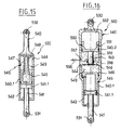
- FIG. 15 shows in section the special control rod 500 which makes it possible to organize the pivoting of the balance 12, in accordance with a sequential embodiment of the two pivoting movements.
- a sliding part with a piston 541.1 moving in a hollow body 540.1, with an associated chamber 542 open to the air.
- organs ensuring the hydraulic control of elongation or shortening of the telescopic rod 500.
- the hollow body 540.1 in fact receives a piston 546 which slides on a fixed inner rod 547 pierced with orifices 548.
- the body 540.1 is further provided with an orifice 544 which can be connected either to a source of hydraulic pressure, or to a hydraulic tank, the corresponding chamber 549 then being occupied by hydraulic fluid.
- the position illustrated in Figure 15 corresponds to the control of maximum elongation, that is to say a movement of descent of the train.
- a sensor will then be used to detect the correct position of the pendulum at the end of pivoting, in order to raise the landing gear leg.
- FIG. 16 illustrates in section a variant of the telescopic connecting rod of FIG. 15, variant in which the connecting rod 500 also includes an oleo-pneumatic emergency system 550 making it possible, in the event of a hydraulic failure, to pivot the balance 12 by the action of an associated internal pusher 553.
- the connecting rod 500 differs from the preceding connecting rod by the presence, beyond an intermediate fixed bottom 558 of a piston 551 sliding in an extension 540.2 of the body of the connecting rod, which piston delimits a hydraulic chamber 555 through which a internal pusher 553 passing through the fixed bottom 558, and a chamber 552 occupied by a high pressure gaseous fluid.
- An orifice 557 is associated with the hydraulic chamber 555, which orifice is connected to a solenoid valve 556 for emergency control.
- the means for controlling the pivoting of the balance consists of a hydraulic cylinder integrated in the shock absorber.
- the shock absorber 15 is then hooked at point 603 directly on the portion 10.1 of the rigid box 10, and the lower part 600 of this shock absorber 15 is articulated at point 17 on the appendix 16 of the balance wheel 12. In in this case, there is no longer an appendage formed in front of this balance 12, which balance is in this case elongated.
- a telescopic rod 661 slides, here in the position of maximum extension by pressing the associated stops 669.
- the piston 662 of the rod 661 has diaphragm openings 663, and the upper part of this rod is guided by a disc 664 carried by a fixed rod 666, which disc also has orifices forming a diaphragm 665, so that the fluid chamber 668 communicates with the upper part of the damper, the fluid surface being in direct contact with a gaseous fluid 667, in accordance with an embodiment well known in the field of shock absorbers.
- the telescopic rod 661 also has an intermediate fixed bottom 672 below which there is a hydraulic cylinder with a rod 670 sliding in the telescopic rod 661.
- the piston of this rod 670 slides in a chamber 671 and, in the high position of this rod 670 (position illustrated in FIG. 18), said rod is retained by a claw locking system 673 held by a pusher 674 subjected to the action of a thrust spring 675, said pusher being hollow to allow the hydraulic fluid entering the rod 670 to pass through a lateral orifice 676 and a conduit axial 677.
- the chamber 671 is further provided with a fluid orifice 678.
- the pressurized fluid is supplied through the orifice 676 of the rod 670, which has the effect of pushing the pusher 674 down against the action of the associated spring 675, and of unlocking the system to claws 673, which authorizes the exit of the internal telescopic rod 670 (the orifice 678 being put on the cover), and consequently the pivoting of the pendulum 12.
- the closure is controlled orifice 676, or a pressure maintenance, in order to have a locking in position by the hydraulic fluid.
- the normal lifting is then carried out by actuating the operating cylinder 20, the damper 15 then behaving like a monolithic assembly.
- the procedure is the opposite, first actuating the operating cylinder 20, then, when the low position of the rigid box can be detected (for example by means of a sensor associated with the counter locking plug in the bottom gear position), pressure fluid is then admitted at the level of the orifice 678, the orifice 676 then being connected to the cover, which causes the retracting of the telescopic inner rod 670, up to when it is locked by the claw system 673, the fluid supply being stopped when the lock has been detected.
- the raising of the telescopic rod 670 thus produces the desired pivoting movement of the balance 12, until the final position of the train is obtained.
Abstract
Description
L'invention concerne les trains d'atterrissage d'aéronef, du type à relevage latéral, et plus particulièrement un train comportant une jambe articulée sur une structure d'aéronef et équipée inférieurement d'un train de roues, et un vérin de manoeuvre assurant le pivotement de cette jambe autour de son axe.The invention relates to aircraft landing gears, of the side-lift type, and more particularly to a train comprising a leg articulated on an aircraft structure and equipped below with a set of wheels, and an operating jack ensuring the pivoting of this leg around its axis.
On connaît de nombreux trains d'atterrissage à relevage latéral dans lesquels la jambe de train est montée pour tourner autour d'un axe qui est parallèle à l'axe central de l'aéronef, ladite jambe se présentant sous la forme d'un caisson d'amortisseur dans lequel coulisse une tige télescopique supportant un train de roues (on pourra par exemple se référer au document US-A-4.406.432). Dans ce cas, le relevage est organisé dans un plan parfaitement transversal, selon une trajectoire qui est un quart de cercle contenu dans ce plan transversal. Cette disposition est avantageuse pour l'organisation du logement du train d'atterrissage, dans la mesure où la roue peut passer avec un faible jeu entre deux cadres de la structure de l'aéronef. Cependant, il n'est pas toujours possible de faire coïncider les positions des cadres de la structure d'aéronef avec la position nécessaire des atterrisseurs pour une répartition souhaitable des charges, vis-à-vis du centre de gravité de l'aéronef, entre l'atterrisseur avant et les atterrisseurs principaux. Ainsi, en position train bas, l'axe des roues des atterrisseurs principaux peut en particulier être décalé vers l'arrière des cadres de structure, ce qui implique d'avancer la ou les roues en cours de relevage du train.Numerous side lift landing gear are known in which the train leg is mounted to rotate about an axis which is parallel to the central axis of the aircraft, said leg being in the form of a box shock absorber in which slides a telescopic rod supporting a train of wheels (one can for example refer to document US-A-4,406,432). In this case, the lifting is organized in a perfectly transverse plane, according to a trajectory which is a quarter of a circle contained in this transverse plane. This arrangement is advantageous for the organization of the landing gear housing, insofar as the wheel can pass with little play between two frames of the aircraft structure. However, it is not always possible to make the positions of the frames of the aircraft structure coincide with the necessary position of the undercarriages for a desirable distribution of the loads, with respect to the center of gravity of the aircraft, between the front undercarriage and the main undercarriages. Thus, in the low gear position, the axis of the wheels of the main undercarriages can in particular be offset towards the rear of the structural frames, which implies advancing the wheel or wheels in the process of lifting the train.
On utilise par exemple des jambes de train d'atterrissage constituées par un caisson rigide articulé sur la structure d'aéronef, et par un balancier porteur de roues articulé en extrémité de ce caisson. Pour pouvoir passer de la position train bas, dans laquelle l'axe d'articulation du balancier est essentiellement perpendiculaire au plan longitudinal médian de l'aéronef, à la position train haut dans laquelle les roues sont avancées plus en avant pour passer dans le logement associé, on utilise en général un axe longitudinal incliné comme axe de pivotement du caisson. Cependant, la trajectoire est alors contraignante, en particulier lorsque le déport est important entre la structure de l'aéronef et les roues de l'atterrisseur en position train bas, et, si l'on recherche avant tout la compacité du logement, il y a un risque de devoir adapter la partie inférieure de la structure de l'aéronef, par exemple en dégageant des parties basses des cadres délimitant ce logement.Landing gear legs are used, for example, constituted by a rigid box articulated on the aircraft structure, and by a wheel-bearing balance articulated at the end of this box. In order to be able to pass from the low gear position, in which the articulation axis of the pendulum is essentially perpendicular to the median longitudinal plane of the aircraft, to the high gear position in which the wheels are advanced further forward to pass into the associated housing, a generally inclined longitudinal axis is used as the pivot axis of the box. However, the trajectory is then constraining, in particular when the offset is significant between the structure of the aircraft and the undercarriage wheels in the low gear position, and, if the compactness of the housing is primarily sought, has a risk of having to adapt the lower part of the structure of the aircraft, for example by releasing lower parts of the frames delimiting this housing.
L'invention a précisément pour but de résoudre ce problème, en concevant un train d'atterrissage ne présentant pas les inconvénients et/ou limitations précités, au regard de la complexité structurelle du train et des contraintes affectant la structure de l'aéronef pour la rentrée de ce train et son logement en position train haut.The object of the invention is precisely to solve this problem, by designing a landing gear which does not have the aforementioned drawbacks and / or limitations, having regard to the structural complexity of the train and the constraints affecting the structure of the aircraft for the re-entry of this train and its housing in the high train position.
L'état de la technique est également illustré par le document DE-C-1.272.736 dans lequel est décrit un train d'atterrissage à relevage latéral, comportant trois balanciers articulés sur une structure à deux bras. En position train bas, les trois roues du train sont disposées dans deux plans parallèles voisins (avec la roue avant et la roue arrière dans le plan extérieur, et la roue centrale dans le plan intérieur), pour former un groupe compact. Pour éviter d'avoir un logement de réception de hauteur excessive, il est prévu, avant de relever le train, d'avancer la roue avant et la roue centrale en faisant pivoter leur balancier respectif, de façon à pouvoir amener les trois roues dans un plan horizontal commun en position train haut.The state of the art is also illustrated by document DE-C-1,272,736 in which a landing gear with lateral lift is described, comprising three pendulums articulated on a structure with two arms. In the low gear position, the three wheels of the train are arranged in two neighboring parallel planes (with the front wheel and the rear wheel in the outside plane, and the central wheel in the inside plane), to form a compact group. To avoid having an excessively high reception housing, it is planned, before raising the train, to advance the front wheel and the central wheel by pivoting their respective pendulum, so as to be able to bring the three wheels in a common horizontal plane in high gear position.
Cette approche, particulière à un train à trois roues, a cependant l'inconvénient d'augmenter considérablement l'encombrement du logement dans le sens longitudinal. De plus, la structure utilisée est complexe, car le relevage de la roue centrale et le relevage des roues avant et arrière doivent être assurés par des moyens séparés.This approach, specific to a three-wheeled train, has the disadvantage of considerably increasing the size of the housing in the longitudinal direction. In addition, the structure used is complex, because the lifting of the central wheel and the lifting of the front and rear wheels must be insured by separate means.
On peut enfin citer le document GB-A-911.121 au titre de l'arrière-plan technologique, dans lequel est décrit un train d'atterrissage à relevage vertical agencé pour un encombrement minimal en hauteur en position train haut (au détriment de l'encombrement du logement dans le sens longitudinal).Finally, we can cite the document GB-A-911.121 under the technological background, in which is described a landing gear with vertical lift arranged for a minimum space requirement in height in the high gear position (to the detriment of the dimensions of the housing in the longitudinal direction).
L'invention a ainsi pour objet de réaliser un train d'atterrissage du type à relevage latéral, dont la structure permet d'optimiser la cinématique des composants mobiles pour passer d'une position à l'autre dudit train en se conformant à une trajectoire optimale au regard de la géométrie particulière de l'aéronef, tout en facilitant le contrôle de cette trajectoire lors des mouvements de relevage ou de descente du train, de façon à pouvoir utiliser un logement de compacité optimale dans le sens longitudinal sans risque de perturbation lors de l'approche des roues.The object of the invention is therefore to produce a landing gear of the side-lift type, the structure of which makes it possible to optimize the kinematics of the moving components to pass from one position to the other of said train while conforming to a trajectory. optimal with regard to the particular geometry of the aircraft, while facilitating the control of this trajectory during lifting or lowering movements of the train, so as to be able to use a housing of optimal compactness in the longitudinal direction without risk of disturbance during approaching the wheels.
Il s'agit plus particulièrement d'un train d'atterrissage d'aéronef, du type à relevage latéral, comportant une jambe articulée sur une structure d'aéronef et équipée inférieurement d'un train de roues, et un vérin de manoeuvre assurant le pivotement de cette jambe autour de son axe, caractérisé en ce que :
- la jambe est formée d'un caisson rigide articulé sur la structure d'aéronef, et d'un balancier porteur de roues articulé en extrémité du caisson en pouvant tourner autour d'un axe qui, en position train bas, est sensiblement perpendiculaire au plan longitudinal médian de l'aéronef ;
- un amortisseur relie le caisson au balancier, en étant articulé sur ledit balancier en un point situé entre l'axe d'articulation de ce balancier et l'axe du train de roues ;
- le balancier est en outre directement relié à un moyen de commande de pivotement qui est agencé pour diminuer, lors du relevage du train, l'angle que forment la direction du caisson et la direction du balancier, de façon qu'en position train haut ledit balancier s'étende sensiblement dans le prolongement dudit caisson, et inversement pour augmenter cet angle lors de la descente dudit train, en se conformant à une trajectoire prédéterminée.
- the leg is formed of a rigid box articulated on the aircraft structure, and of a wheel carrying pendulum articulated at the end of the box being able to rotate around an axis which, in the low gear position, is substantially perpendicular to the plane median longitudinal of the aircraft;
- a shock absorber connects the box to the balance, being articulated on said balance at a point located between the axis of articulation of this balance and the axis of the wheel train;
- the balance is also directly connected to a pivoting control means which is arranged to reduce, when lifting the train, the angle formed by the direction of the box and the direction of the pendulum, so that in the top gear position said pendulum extends substantially in the extension of said box, and vice versa to increase this angle during the descent of said train, by conforming to a predetermined trajectory.
L'utilisation combinée des deux axes de pivotement et du moyen de commande de pivotement du balancier permet d'obtenir une définition optimale de la trajectoire et un excellent contrôle de cette trajectoire, sans complication notable de la structure du train d'atterrissage.The combined use of the two pivot axes and of the pendulum pivot control means provides an optimal definition of the trajectory and excellent control of this trajectory, without any noticeable complication of the structure of the landing gear.
De préférence, le caisson rigide est articulé sur la structure d'aéronef en pouvant tourner autour d'un axe qui est sensiblement parallèle à l'axe central de l'aéronef, ce qui simplifie l'agencement de la structure de l'aéronef.Preferably, the rigid box is articulated on the aircraft structure by being able to rotate about an axis which is substantially parallel to the central axis of the aircraft, which simplifies the arrangement of the structure of the aircraft.
Plusieurs variantes peuvent en outre être envisagées dans le cadre de l'invention, selon la structure particulière du moyen de commande de pivotement.Several variants can also be envisaged in the context of the invention, depending on the particular structure of the pivot control means.
Dans un premier mode d'exécution possible, le moyen de commande de pivotement du balancier est constitué par un système articulé monté sur le caisson rigide, ce système comportant une triangulation sur laquelle est accroché l'amortisseur et un organe de liaison articulé sur la structure d'aéronef, en étant agencé de façon à pousser (respectivement tirer) sur cet amortisseur lors du relevage (respectivement de la descente) du train.In a first possible embodiment, the means for controlling the pivoting of the balance consists of an articulated system mounted on the rigid box, this system comprising a triangulation on which the shock absorber is hung and a connecting member articulated on the structure aircraft, being arranged to push (respectively pull) on this shock absorber during lifting (respectively descent) of the train.
Dans ce cas, on pourra prévoir que le système articulé inclut un levier articulé sur le caisson rigide, ledit levier comportant un premier bras qui définit, avec une bielle reliant ce bras au point d'accrochage de l'amortisseur, un alignement de verrouillage en position train bas, et un second bras qui est directement attaqué par l'organe de liaison articulé sur la structure d'aéronef. En outre, selon que l'on souhaite avoir deux mouvements de pivotement réalisés simultanément ou séquentiellement, on prévoira que l'organe de liaison est réalisé sous la forme d'une bielle ou d'un vérin hydraulique.In this case, provision could be made for the articulated system to include a lever articulated on the rigid box, said lever comprising a first arm which defines, with a connecting rod connecting this arm to the point of attachment of the shock absorber, a locking alignment in low gear position, and a second arm which is directly attacked by the link member articulated on the aircraft structure. In addition, depending on whether one wishes to have two pivoting movements carried out simultaneously or sequentially, provision will be made for the connecting member to be produced in the form of a connecting rod or a hydraulic cylinder.
Dans un autre mode d'exécution possible, le moyen de commande de pivotement du balancier est constitué par une came articulée sur le caisson rigide, avec laquelle coopère un galet monté sur un appendice du balancier, et par un organe de liaison reliant cette came articulée à la structure d'aéronef, ladite came incluant une butée contre laquelle ledit galet est maintenu en appui, en position train bas, par la poussée exercée par l'amortisseur sur le balancier, et ledit organe de liaison étant agencé pour escamoter (respectivement replacer) ladite butée lors du relevage (respectivement de la descente) du train.In another possible embodiment, the means for controlling the pivoting of the balance consists of a cam articulated on the rigid box, with which a roller mounted on an appendage of the balance cooperates, and by a connecting member connecting this articulated cam to the aircraft structure, said cam including a stop against which said roller is held in abutment, in the low gear position, by the thrust exerted by the shock absorber on the pendulum, and said connecting member being arranged to retract (respectively replace ) said stop when the train is lifted (respectively lowered).
Selon le cas, comme précédemment, on pourra prévoir que l'organe de liaison est réalisé sous la forme d'une bielle ou d'un vérin hydraulique.As the case may be, as previously, provision may be made for the connecting member to be produced in the form of a connecting rod or of a hydraulic cylinder.
Dans un autre mode d'exécution possible, le moyen de commande de pivotement du balancier est constitué par une bielle télescopique reliant un appendice du balancier à un bras d'un levier qui est articulé sur un appendice du caisson rigide, l'autre bras de ce levier étant relié à la structure d'aéronef par l'intermédiaire d'une bielle associée.In another possible embodiment, the means for controlling the pivoting of the balance consists of a telescopic connecting rod connecting an appendage of the balance to an arm of a lever which is articulated on an appendage of the rigid box, the other arm of this lever being connected to the aircraft structure via an associated connecting rod.
Dans encore un autre mode d'exécution possible, le moyen de commande de pivotement du balancier est constitué par une bielle télescopique à système intégré de commande hydraulique d'allongement ou de raccourcissement, reliant un appendice du balancier à un appendice du caisson rigide. En particulier, la bielle télescopique peut en outre inclure un système oléo-pneumatique de secours permettant, en cas de panne hydraulique, de faire pivoter le balancier par action d'un poussoir interne associé.In yet another possible embodiment, the means for controlling the pivoting of the balance consists of a telescopic connecting rod with an integrated system for hydraulic extension or shortening control, connecting an appendage of the balance to an appendage of the rigid box. In particular, the telescopic connecting rod can also include an oleo-pneumatic emergency system making it possible, in the event of a hydraulic failure, to pivot the balance by the action of an associated internal pusher.
Dans un autre mode d'exécution possible, le moyen de commande de pivotement du balancier est constitué par un vérin hydraulique intégré dans l'amortisseur, ledit amortisseur comportant à cet effet une tige télescopique équipée intérieurement d'une tige-piston et d'un organe de verrouillage associé, laquelle tige-piston est accrochée sur un appendice du balancier.In another possible embodiment, the means for controlling the pivoting of the balance consists of a hydraulic cylinder integrated in the shock absorber, said shock absorber comprising for this purpose a telescopic rod fitted internally with a piston rod and a locking device associated, which piston rod is hung on an appendage of the pendulum.
D'autres caractéristiques et avantages de l'invention apparaîtront plus clairement à la lumière de la description qui va suivre et des dessins annexés, concernant différents modes d'exécution particuliers, en référence aux figures où :
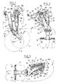
- les figures 1 à 3 illustrent un train d'atterrissage conforme à l'invention (les figures 1 et 2 étant des vues respectivement latérale et frontale en position train bas, et la figure 3 une vue frontale en position train haut), avec un moyen de commande de pivotement du balancier constitué par un système articulé incluant un alignement de verrouillage en position train bas ;
- les figures 4 à 6 sont des vues analogues illustrant une variante proche du mode de réalisation précédent, dans laquelle l'alignement de verrouillage en position train bas est verrouillé non pas déplié mais replié;
- les figures 7 à 9 (la figure 9 montre encore la position train haut, mais ici en vue de dessus) illustrant un autre mode d'exécution, dans lequel le moyen de commande de pivotement est constitué par une butée escamotable portée par une came articulée et une bielle de liaison;
- les figures 1O et 11 illustrent un autre mode d'exécution dans lequel le moyen de commande de pivotement est constitué par une bielle télescopique, laquelle bielle est représentée sur la coupe axiale de la figure 12 ;
- les figures 13 et 14 illustrent une variante proche du mode de réalisation précédent, dans laquelle la bielle télescopique inclut un système intégré de commande hydraulique d'allongement ou de raccourcissement, laquelle bielle est représentée en coupe sur la figure 15 ;
- la figure 16 illustre en coupe une variante de la bielle télescopique de la figure 15, qui inclut en outre un système oléo-pneumatique de secours ;
- la figure 17 illustre un autre mode d'exécution dans lequel le moyen de commande de pivotement est constitué par un vérin hydraulique intégré dans l'amortisseur, cet amortisseur spécial à plusieurs fonctions étant représenté en coupe sur la figure 18.
- Figures 1 to 3 illustrate a landing gear according to the invention (Figures 1 and 2 being respectively lateral and front views in the low gear position, and Figure 3 a front view in the high gear position), with means of the pendulum pivoting control constituted by an articulated system including a locking alignment in the low gear position;
- Figures 4 to 6 are similar views illustrating a variant close to the previous embodiment, in which the locking alignment in the low gear position is locked not unfolded but folded;
- Figures 7 to 9 (Figure 9 also shows the top gear position, but here in top view) illustrating another embodiment, in which the pivot control means is constituted by a retractable stop carried by an articulated cam and a connecting rod;
- Figures 1O and 11 illustrate another embodiment in which the pivoting control means is constituted by a telescopic rod, which rod is shown in the axial section of Figure 12;
- FIGS. 13 and 14 illustrate a variant close to the previous embodiment, in which the telescopic connecting rod includes an integrated hydraulic control system for elongation or shortening, which rod is shown in section in FIG. 15;
- FIG. 16 illustrates in section a variant of the telescopic connecting rod of FIG. 15, which also includes an oleo-pneumatic emergency system;
- FIG. 17 illustrates another embodiment in which the pivoting control means is constituted by a hydraulic cylinder integrated in the shock absorber, this special shock absorber with several functions being shown in section in FIG. 18.
On va maintenant décrire, en se référant aux figures 1 à 3, un train d'atterrissage T conforme à l'invention, ledit train étant du type à relevage latéral, et étant reçu dans un logement associé L de la structure d'aéronef concernée, ledit logement étant délimité par deux cadres transversaux C espacés entre eux d'une distance correspondant sensiblement au diamètre des roues R de ce train d'atterrissage.We will now describe, with reference to Figures 1 to 3, a landing gear T according to the invention, said train being of the side lift type, and being received in an associated housing L of the aircraft structure concerned , said housing being delimited by two transverse frames C spaced apart from each other by a distance corresponding substantially to the diameter of the wheels R of this landing gear.
Le train d'atterrissage T comporte une jambe 5O articulée sur une structure d'aéronef S et équipée inférieurement d'un train de roues R, un vérin de manoeuvre 2O assurant le pivotement de cette jambe autour de son axe.The landing gear T comprises a
La jambe 5O est formée d'un caisson rigide 1O, articulé par sa portion supérieure 1O.1 sur la structure d'aéronef en pouvant tourner autour d'un axe 11 est ici sensiblement parallèle à l'axe central de l'aéronef (il va de soi cependant que l'axe 11 pourra présenter une légère inclinaison par rapport au plan longitudinal médian de l'aéronef et/ou à un plan transversal), et d'un balancier porteur de roues 12 articulé en extrémité du caisson 10 en pouvant tourner autour d'un axe 13 qui, en position train bas, est sensiblement perpendiculaire au plan longitudinal médian de l'aéronef (dans la pratique, on s'arrange pour avoir cette perpendicularité sous charge pour limiter l'usure des pneus). L'axe 14 des fusées 26 de roues est ici agencé en bout du balancier 12. La direction de l'avion est en outre schématisée par la flèche 30. Dans le mode de réalisation particulier représenté ici, les axes principaux de pivotement, c'est-à-dire l'axe 11 de pivotement du caisson rigide 10, et l'axe 13 de pivotement du balancier porteur de roues 12, sont sensiblement orthogonaux.The leg 5O is formed of a rigid box 1O, articulated by its upper portion 1O.1 on the aircraft structure while being able to rotate around an
Ainsi que cela est mieux visible sur la vue en position train bas de la figure 2, on a également prévu des moyens de contreventement de type traditionnel associés à la jambe 50, avec ici une contre-fiche articulée comportant un bras 22 articulé sur un appendice 24 du caisson rigide 10, et un bras 23 articulé en un point 25 sur la structure d'aéronef. On distingue également sur cette figure un appendice supérieur 18 solidaire du caisson rigide 10, en extrémité duquel vient s'articuler, en un point 19, le vérin de manoeuvre 20 associé, dont le corps est articulé en un point 21 sur la structure d'aéronef. Il va de soi que la contrefiche constituée par les bras 22 et 23 pourra être équipée de tout système de verrouillage et déverrouillage de type traditionnel, un tel système n'étant pas illustré ici.As is better visible in the view in the low gear position of FIG. 2, there are also provided bracing means of the traditional type associated with the
Un amortisseur 15 relie en outre le caisson rigide 10 au balancier oscillant 12, cet amortisseur étant articulé sur le balancier en un point 17 d'un appendice 16 dudit balancier, lequel point 17 est situé entre l'axe d'articulation 13 de ce balancier et l'axe 14 du train de roues R.A
Conformément à une caractéristique essentielle de l'invention, le balancier 12 est en outre directement relié, ici par l'intermédiaire de l'amortisseur 15, à un moyen de commande de pivotement qui est agencé pour diminuer, lors du relevage du train, l'angle A que forment la direction du caisson rigide 10 et la direction du balancier 12, de façon qu'en position train haut ledit balancier s'étende sensiblement dans le prolongement dudit caisson, et inversement pour augmenter cet angle lors de la descente dudit train, en se conformant à une trajectoire prédéterminée.In accordance with an essential characteristic of the invention, the
En l'espèce, le moyen de commande de pivotement du balancier est constitué par un système articulé 100 associé à l'accrochage de la partie haute de l'amortisseur 15. Plus précisément, le système articulé 100 comporte une triangulation sur laquelle est accroché l'amortisseur 15 au niveau d'un point 103, et un organe de liaison 110 articulé sur la structure d'aéronef en un point d'extrémité 111 dudit organe. On distingue ainsi sur la figure 2 une première bielle 101 articulée sur un appendice latéral 102 du caisson rigide 10, et une seconde bielle 104 articulée coaxialement à la première bielle 101 au niveau du point d'accrochage 103 de l'amortisseur 15, cette seconde bielle 104 étant articulée à son autre extrémité sur un levier 105 lui-même articulé en 109 sur un appendice 106 du caisson rigide 10. Ainsi que cela est mieux visible sur la figure 1, on utilise en réalité, de part et d'autre d'un plan longitudinal médian de l'amortisseur, un double appendice 102 formant une chape sur laquelle sont articulées deux bielles 101 reliées à deux bielles 104, agencées symétriquement de part et d'autre de ce plan. On pourra naturellement prévoir un raccordement de ces bielles symétriques. De même, un double appendice 106 est également prévu, définissant une chape inférieure, pour l'articulation du levier 105 faisant partie du système articulé 100. Le levier 105 comporte un premier bras 107 qui définit, avec la bielle 104 reliant ce bras au point d'accrochage 103 de l'amortisseur 15, un alignement de verrouillage en position train bas (position de la figure 2), et un second bras 108 qui est directement attaqué par l'organe de liaison 110 articulé sur la structure d'aéronef. En l'espèce, l'organe de liaison 110 est réalisé sous la forme d'une bielle rigide. Ainsi qu'on le verra par la suite, il peut s'avérer intéressant de remplacer cette bielle par un vérin hydraulique, dans le cadre d'une réalisation séquentielle des mouvements de pivotement du train d'atterrissage.In this case, the means for controlling the pivoting of the balance consists of an articulated
Le système articulé 100 comporte ainsi une triangulation 101, 104, 105 sur laquelle est accroché l'amortisseur 15, ainsi que l'organe de liaison 110 articulé sur la structure d'aéronef, et ce système est agencé de façon à pousser (respectivement tirer) sur cet amortisseur lors du relevage (respectivement de la descente) du train d'atterrissage T. En effet, ainsi que cela est mieux visible sur la représentation train haut donnée à la figure 3, on constate que les bielles 101 et 104 ont exercé une poussée sur l'amortisseur 15, comme schématisé par la flèche 31, laquelle poussée est transmise directement au balancier oscillant 12, ce qui a pour effet de diminuer l'angle A formé par la direction du caisson rigide 10 et la direction du balancier 12. Sur la figure 1, on a représenté la position train bas normal, qui est ici une position intermédiaire entre la position haute des roues correspondant à une compression maximale de l'amortisseur 15, et une position basse des roues dans laquelle l'angle A est pratiquement nul, c'est-à-dire que le balancier 12 s'étend alors dans le prolongement direct (en vue latérale selon la figure 1) du caisson rigide 10, cette position étant atteinte lorsque le train d'atterrissage atteint sa position finale de réception dans le logement L associé, les roues R étant alors progressivement avancées lors du pivotement de la jambe 50, pour finalement venir passer précisément entre les deux cadres concernés C délimitant le logement associé L. On peut de ce fait avoir un logement L qui est de compacité optimale dans le sens longitudinal.The articulated
Le système articulé 100 est ici exclusivement constitué par des éléments mécaniques rigides, de sorte que la cinématique est parfaitement définie à tout instant du mouvement de relevage ou de descente du train. Lors de la descente du train, les bielles 101 et 104 auxquelles est attaché supérieurement l'amortisseur 15 exercent une traction sur cet amortisseur tendant à le remonter, laquelle traction a pour effet de faire pivoter le levier oscillant 12 en augmentant l'angle A associé, et ce jusqu'à ce que la position finale train bas soit atteinte.The articulated
Il convient de noter que la bielle 104 et le bras 107 du levier 105 définissent tous deux un alignement de verrouillage en position train bas, comme illustré sur la figure 2, cet alignement étant ici verrouillé déplié. Il va de soi que le système articulé pourrait être agencé différemment, et la variante qui va être décrite ci-après comporte un agencement différent avec un alignement de verrouillage en position train bas qui est verrouillé replié. Par ailleurs, si l'on souhaite avoir deux mouvements de pivotement réalisés non plus simultanément, mais séquentiellement, il suffit de remplacer la bielle 110 du système articulé 100 qui vient d'être décrit par un vérin hydraulique de pivotement(variante non représentée ici), lequel vérin doit alors naturellement être accroché non plus sur la structure d'aéronef, mais sur le caisson rigide. Dans ce cas, pour le relevage du train, on commence par alimenter ce vérin de pivotement pour faire pivoter le basculeur 12 en faisant avancer les roues associées, puis, une fois la position angulaire désirée atteinte (cette position étant par exemple détectée au moyen d'un capteur et d'une cible), on alimente le vérin de manoeuvre 20 pour déclencher le pivotement de la jambe qui se comporte alors comme un ensemble rigide monolithique.It should be noted that the connecting
Les figures 4 à 6 illustrent une variante qui est proche du mode de réalisation précédent qui vient d'être décrit, de sorte que l'on a conservé les mêmes références pour les éléments homologues. Le moyen de pivotement du balancier, référencé 200, est là encore constitué par un système articulé monté sur le caisson rigide 10, ce système comportant une triangulation sur laquelle est accroché l'amortisseur 15, et un organe de liaison 210 articulé sur la structure d'aéronef, en étant agencé de façon à pousser (respectivement tirer) sur cet amortisseur lors du relevage (respectivement de la descente) du train. Le système articulé 200 est cependant agencé différemment par rapport au système articulé de la variante précédemment décrite, comme expliqué ci-après.Figures 4 to 6 illustrate a variant which is close to the previous embodiment which has just been described, so that the same references have been kept for the homologous elements. The pivoting means of the pendulum, referenced 200, is again constituted by an articulated system mounted on the
Le caisson rigide 10 présente en partie haute un appendice central 202, sur lequel vient s'articuler une bielle 201 d'une part et un levier 205 d'autre part. Le levier 205 est articulé en pouvant tourner autour d'un axe 209, et comporte un premier bras 207 se raccordant à une bielle 204, cette dernière rejoignant la bielle 201 au niveau du point d'accrochage 203 de l'amortisseur 15. L'autre bras 208 du levier 205 est quant à lui directement attaqué par l'organe de liaison 210 articulé sur la structure d'aéronef, lequel organe est en l'espèce réalisé sous la forme d'une bielle rigide. Ainsi que cela est visible sur la figure 5, on retrouve ainsi une triangulation 201, 204, 205 sur laquelle est accroché l'amortisseur 15, et le bras 207 du levier 205 définit avec la bielle 204 un alignement de verrouillage en position train bas, mais cet alignement est alors verrouillé replié (position de la figure 5). Lors du relevage du train T, les bielles 201 et 204 exercent une poussée sur l'amortisseur 15, et par suite induisent un pivotement du balancier 12 tendant à diminuer l'angle A pour faire avancer les roues R, comme pour la variante précédemment décrite. Ainsi que cela est mieux visible sur la figure 4, on a illustré ici une double bielle 204, une double bielle 201, et un double bras 207 du levier 205, avec un agencement symétrique de part et d'autre d'un plan médian de l'amortisseur, le bras 208 dudit levier étant quant à lui agencé en saillant latéralement. Comme précédemment, lorsque l'on souhaite réaliser les deux mouvements de pivotement de façon séquentielle, il suffit alors de remplacer la bielle rigide 210 par un vérin hydraulique de pivotement. Le processus de relevage ou de descente du train est alors réalisé de la même façon que ce qui a été précédemment décrit dans le cas d'une réalisation séquentielle des deux mouvements de pivotement.The
On va maintenant décrire un autre mode d'exécution de l'invention, en se référant aux figures 7 à 9.We will now describe another embodiment of the invention, with reference to FIGS. 7 to 9.
On retrouve comme précédemment une jambe constituée par un caisson rigide et un balancier articulé, de sorte que les mêmes références ont été conservées pour les composants communs. A la différence des trains d'atterrissage précédents, on constate tout d'abord que l'amortisseur 15 est accroché directement en un point 303 sur la portion 10.1 du caisson rigide entourant l'axe de pivotement 11.We find as before a leg consisting of a rigid box and an articulated balance, so that the same references have been kept for the components common. Unlike the previous landing gear, it is noted first of all that the
La différence essentielle réside dans une structure particulière du moyen de commande du pivotement du balancier, lequel moyen est référencé 300.The essential difference lies in a particular structure of the means for controlling the pivoting of the balance, which means is referenced 300.
Le moyen de commande 300 est constitué par une came 320, articulée autour d'un axe 322 porté par un appendice 321 du caisson rigide 10, came avec laquelle coopère un galet 329 monté en extrémité d'un appendice 328 du balancier 12. Il convient d'organiser le pivotement de la came 320 autour de son axe lors du pivotement du caisson rigide 10 autour de son axe 11 : en l'espèce, ceci est assuré au moyen d'un organe de liaison 325 reliant cette came articulée 320 à la structure d'aéronef. Cet organe de liaison 325 est ici réalisé sous la forme d'une bielle allongée, articulée en 327 sur la came articulée 320, et en 326 sur la structure d'aéronef. La came 320 comporte un profil actif 324 avec lequel coopère le galet 329, ce contour incluant une portion formant butée 324.1 contre laquelle le galet 329 est maintenu en appui, en position train bas (comme illustré sur la figure 7), par la poussée exercée par l'amortisseur 15 sur le balancier 12. Lors du pivotement du caisson rigide 10 autour de son axe 11 par suite de l'actionnement du vérin de manoeuvre 20, la bielle de commande 325 exerce une traction sur la came articulée 320, ce qui dégage le galet 329 de la butée associée 324.1, et par suite libère le pivotement du balancier 12 autour de son axe 13. Lors de ce pivotement, le galet 329 reste au contact de ce profil de came associé 324, jusqu'à ce que soit atteinte la position dans laquelle ledit galet atteint l'extrémité du profil, position qui est illustrée sur la figure 9 et qui correspond à une vue de dessus en position train haut. Ainsi, dès que la butée articulée 320 est escamotée par suite de la traction exercée sur celle-ci par la bielle de commande 325, il y a libération de la détente de l'amortisseur 15 qui peut faire pivoter le balancier 12 afin de faire avancer les roues R lors du pivotement de la jambe du train. La butée 324.1 est ainsi une butée de détente, et le contact est assuré en permanence en position train bas grâce à la réserve de poussée procurée par l'amortisseur 15. Il est intéressant de noter la présence d'un bras 323 venant compléter le profil de came 324 : ce bras, qui n'est naturellement aucunement obligatoire dans la mesure où le galet 329 ne devrait en principe pas venir le contacter, constitue néanmoins une sécurité intéressante garantissant la bonne trajectoire du galet 329, en constituant notamment un organe de sécurité supplémentaire en cas de dégonflage de l'amortisseur 15, car le galet 329 est alors emprisonné au fond de la lumière associée.The control means 300 is constituted by a
Comme précédemment, si l'on souhaite réaliser les deux mouvements de pivotement de façon séquentielle, il suffit alors de remplacer la bielle de commande, en l'espèce la bielle 325, par un vérin hydraulique de pivotement associé commandant le mouvement de pivotement de la came articulée 320. Le processus du relevage comporte alors une étape préliminaire de dégagement de la butée de la came articulée pour libérer le pivotement du balancier, puis l'on retrouve les étapes de pivotement du balancier autour de son axe 13, et enfin le pivotement du caisson rigide 10 autour de son axe 11.As before, if it is desired to carry out the two pivoting movements sequentially, it then suffices to replace the control rod, in this case the
On va maintenant décrire, en se référant aux figures 10 à 12, un autre mode d'exécution du train d'atterrissage selon l'invention, dans lequel on retrouve des organes précédemment décrits, affectés là encore des mêmes références que précédemment.We will now describe, with reference to FIGS. 10 to 12, another embodiment of the landing gear according to the invention, in which there are previously described members, again assigned the same references as above.
La différence essentielle réside dans l'agencement particulier du moyen de commande de pivotement du balancier 12, lequel moyen est ici réalisé sous la forme d'une bielle télescopique 400. Le balancier 12 présente à cet effet un appendice 430 servant à l'accrochage, au point 431, de l'extrémité de la tige 441 de la bielle télescopique. A son autre extrémité, le corps 440 de la bielle télescopique 400 est articulé, en un point 432, sur un bras 436 d'un levier 433 lui-même articulé en 434 sur un appendice 435 du caisson rigide 10, l'autre bras 437 de ce levier étant quant à lui relié à la structure d'aéronef par l'intermédiaire d'une bielle associée 438 articulée en 439 sur la structure d'aéronef.The essential difference lies in the particular arrangement of the means for controlling the pivoting of the
La figure 12 permet de mieux distinguer la structure de la bielle télescopique 400 utilisée ici, et l'on distingue en particulier un piston 441.1 solidaire de la tige 441, et le corps creux 440.1 solidaire du corps 440, dans lequel coulisse ce piston 441.1, ce qui permet d'obtenir une protection complète de la zone de coulissement de ce piston dans la chambre associée 442 qui est ouverte à l'air libre. La position illustrée en figure 12 est une position de butée franche, position dans laquelle les organes mécaniques de butée sont parfaitement protégés contre les agents extérieurs.FIG. 12 makes it possible to better distinguish the structure of the telescopic connecting
On pourra naturellement en variante modifier le corps 440 de cette bielle télescopique 400, de façon à insérer un vérin hydraulique de manoeuvre, ceci dans le cas où l'on souhaiterait avoir une réalisation séquentielle des deux mouvements de pivotement, variante qui va être décrite ci-après en se référant aux figures 13 et 14, et dans laquelle la bielle télescopique inclut dans son corps creux un système intégré de commande hydraulique d'allongement ou de raccourcissement.As a variant, it is naturally possible to modify the
La bielle télescopique 500 est ici directement accrochée, en un point 532, à un appendice 543 solidaire de la portion 10.1 du caisson rigide 10, de sorte que le corps 540 de cette bielle de commande n'est plus accroché sur un système articulé à levier comme c'était le cas pour la variante précédente. La tige 541 de cette bielle est quant à elle articulée en un point 531 sur un appendice 530 du balancier 12. Sur la figure 13, on a représenté le sol S avec l'angle de cabrage CA de l'avion lors du contact des roues R avec le sol S. On retrouve comme précédemment l'angle A défini par la direction du caisson rigide 10 et celle du balancier oscillant 12. On trouve en outre un angle B qui est associé à l'angle de cabrage CA.The
La figure 15 représente en coupe la bielle spéciale de commande 500 qui permet d'organiser le pivotement du balancier 12, conformément à un mode d'exécution séquentiel des deux mouvements de pivotement.FIG. 15 shows in section the
On retrouve comme précédemment une partie coulissante avec un piston 541.1 se déplaçant dans un corps creux 540.1, avec une chambre associée 542 ouverte à l'air libre. On trouve en plus ici, juxtaposés aux composants précédents, des organes assurant la commande hydraulique d'allongement ou de raccourcissement de la bielle télescopique 500. Le corps creux 540.1 reçoit en effet un piston 546 qui coulisse sur une tige intérieure fixe 547 percée d'orifices 548. Le corps 540.1 est en outre muni d'un orifice 544 qui peut être relié soit à une source de pression hydraulique, soit à une bâche hydraulique, la chambre correspondante 549 étant alors occupée par du fluide hydraulique.As previously, there is a sliding part with a piston 541.1 moving in a hollow body 540.1, with an associated
La position illustrée sur la figure 15 correspond à la commande d'un allongement maximum, c'est-à-dire à un mouvement de descente du train. Pour le relevage du train, il suffit de mettre l'orifice 544 en communication avec la bâche pour que le piston 546 puisse alors librement remonter, en libérant l'action de la tige-piston 541 correspondant à l'obtention du pivotement désiré du balancier autour de son axe 13. De préférence, on prévoira alors un capteur servant à détecter la position correcte du balancier en fin de pivotement, afin de relever la jambe de l'atterrisseur.The position illustrated in Figure 15 corresponds to the control of maximum elongation, that is to say a movement of descent of the train. For lifting the train, it is enough to put the
La figure 16 illustre en coupe une variante de la bielle télescopique de la figure 15, variante dans laquelle la bielle 500 inclut en outre un système oléo-pneumatique de secours 550 permettant, en cas de panne hydraulique, de faire pivoter le balancier 12 par action d'un poussoir interne associé 553.FIG. 16 illustrates in section a variant of the telescopic connecting rod of FIG. 15, variant in which the connecting
On retrouve comme précédemment la tige-piston 541, le piston 546 et la chambre 549 associée munie de son orifice 544 correspondant au fonctionnement normal de la commande d'allongement ou de raccourcissement de la bielle. La bielle 500 se démarque de la bielle précédente par la présence, au-delà d'un fond fixe intermédiaire 558 d'un piston 551 coulissant dans une extension 540.2 du corps de la bielle, lequel piston délimite une chambre hydraulique 555 dans laquelle passe un poussoir interne 553 traversant le fond fixe 558, et une chambre 552 occupée par un fluide gazeux haute pression. Un orifice 557 est associé à la chambre hydraulique 555, lequel orifice est relié à une électrovanne 556 de commande en secours. Lorsque l'électrovanne 556 est excitée, l'ouverture de celle-ci autorise la descente du piston 551 sous l'action du fluide gazeux haute pression avec simultanément une sortie du fluide hydraulique de la chambre 555, le poussoir interne 553 repoussant alors le piston 546 depuis sa position illustrée en traits mixtes jusqu'à une position d'allongement maximum illustrée en trait continu sur la figure 16. Il n'est en réalité aucunement nécessaire que le système de secours assure la position "tout détendu" correspondant à cette représentation en trait continu : il suffit en effet que ce système ramène le balancier dans une position telle que l'angle B soit suffisant pour assurer un atterrissage correct. Ainsi que cela a été représenté à la figure 17, ce système peut même être supprimé si l'on prévoit un agencement différent de la géométrie, avec un balancier 12 allongé, ou encore un circuit d'alimentation secours supplémentaire. Si ce système de secours est utilisé, il convient ensuite de ramener du fluide sous pression via l'électrovanne 556, puis de boucher l'orifice correspondant 557 en cours de relevage, afin de réinitialiser le système de sécurité pour le relevage suivant.We find as before the
On va maintenant décrire un autre mode d'exécution, en se référant plus particulièrement à la figure 18, dans lequel le moyen de commande de pivotement du balancier est constitué par un vérin hydraulique intégré dans l'amortisseur.We will now describe another embodiment, with particular reference to Figure 18, in which the means for controlling the pivoting of the balance consists of a hydraulic cylinder integrated in the shock absorber.
Comme sur la figure 17, l'amortisseur 15 est alors accroché au point 603 directement sur la portion 10.1 du caisson rigide 10, et la partie inférieure 600 de cet amortisseur 15 est articulée au point 17 sur l'appendice 16 du balancier 12. Dans ce cas, on ne trouve plus d'appendice ménagé en avant de ce balancier 12, lequel balancier est dans ce cas allongé.As in FIG. 17, the
Il convient de se référer à la figure 18 pour mieux appréhender la structure de cet amortisseur particulier incluant un vérin hydraulique intégré.Reference should be made to Figure 18 to better understand the structure of this particular damper including an integrated hydraulic cylinder.
En partie haute de l'amortisseur 15, on distingue un cylindre 660 dans lequel coulisse une tige télescopique 661, ici en position d'extension maximale par appui des butées associées 669. Le piston 662 de la tige 661 présente des ouvertures de diaphragme 663, et la partie supérieure de cette tige est guidée par un disque 664 porté par une tige fixe 666, lequel disque présente également des orifices formant diaphragme 665, de telle façon que la chambre de fluide 668 communique avec la partie haute de l'amortisseur, la surface de fluide étant au contact direct d'un fluide gazeux 667, conformément à un mode d'exécution bien connu dans le domaine des amortisseurs.In the upper part of the
La tige télescopique 661 présente en outre un fond fixe intermédiaire 672 en-dessous duquel on trouve un vérin hydraulique avec une tige 670 coulissant dans la tige télescopique 661. Le piston de cette tige 670 coulisse dans une chambre 671 et, en position haute de cette tige 670 (position illustrée sur la figure 18), ladite tige est retenue par un système de verrouillage à griffes 673 maintenu par un poussoir 674 soumis à l'action d'un ressort de poussée 675, ledit poussoir étant creux pour laisser passer le fluide hydraulique rentrant dans la tige 670 par un orifice latéral 676 et un conduit axial 677. La chambre 671 est en outre munie d'un orifice de fluide 678. On peut noter enfin la présence d'une butée supérieure de contact 679 contre laquelle vient en appui la partie supérieure de la tige 670 lorsque celle-ci est en position de rétraction maximale. La tige 670 est par ailleurs reliée par son extrémité au point 17 du balancier 12, comme c'était le cas pour un amortisseur de type standard.The
Pour le relevage du train, le fluide sous pression est amené par l'orifice 676 de la tige 670, ce qui a pour effet de repousser le poussoir 674 vers le bas contre l'action du ressort associé 675, et de déverrouiller le système à griffes 673, ce qui autorise la sortie de la tige télescopique intérieure 670 (l'orifice 678 étant mis à la bâche), et par suite le pivotement du balancier 12. Lorsque la position angulaire désirée du balancier a été atteinte, on commande la fermeture de l'orifice 676, ou encore un maintien en pression, afin d'avoir un verrouillage en position par le fluide hydraulique. On procède ensuite au relevage normal en actionnant le vérin de manoeuvre 20, l'amortisseur 15 se comportant alors comme un ensemble monolithique.For lifting the train, the pressurized fluid is supplied through the
Pour la descente du train, on procède de façon inverse, en actionnant d'abord le vérin de manoeuvre 20, puis, lorsque la position basse du caisson rigide a pu être détectée (par exemple au moyen d'un capteur associé à la contre-fiche de verrouillage en position de train bas), on admet alors du fluide sous pression au niveau de l'orifice 678, l'orifice 676 étant alors relié à la bâche, ce qui provoque la rentrée de la tige intérieure télescopique 670, jusqu'au verrouillage de celle-ci par le système à griffes 673, l'alimentation fluidique étant arrêtée lorsque le verrouillage a été détecté. La remontée de la tige télescopique 670 produit ainsi le mouvement de pivotement désiré du balancier 12, jusqu'à ce que la position finale du train soit obtenue.For the descent of the train, the procedure is the opposite, first actuating the
On pourra naturellement envisager d'autres variantes d'exécution de l'amortisseur 15 illustré en figure 18, par exemple en prévoyant une butée escamotable de la tige coulissante 661 par rapport au corps 66O.We can naturally envisage other alternative embodiments of the
L'invention n'est pas limitée aux modes de réalisation qui viennent d'être décrits, mais englobe au contraire toute variante reprenant, avec des moyens équivalents, les caractéristiques essentielles énoncées plus haut.The invention is not limited to the embodiments which have just been described, but on the contrary encompasses any variant incorporating, with equivalent means, the essential characteristics set out above.
Claims (11)
Applications Claiming Priority (2)
| Application Number | Priority Date | Filing Date | Title |
|---|---|---|---|
| FR9302946 | 1993-03-15 | ||
| FR9302946A FR2702732B1 (en) | 1993-03-15 | 1993-03-15 | AIRCRAFT LANDING GEAR, LATERAL LIFTING TYPE. |
Publications (1)
| Publication Number | Publication Date |
|---|---|
| EP0615901A1 true EP0615901A1 (en) | 1994-09-21 |
Family
ID=9444953
Family Applications (1)
| Application Number | Title | Priority Date | Filing Date |
|---|---|---|---|
| EP94400440A Withdrawn EP0615901A1 (en) | 1993-03-15 | 1994-03-02 | Aircraft landing gear with lateral retraction |
Country Status (2)
| Country | Link |
|---|---|
| EP (1) | EP0615901A1 (en) |
| FR (1) | FR2702732B1 (en) |
Cited By (6)
| Publication number | Priority date | Publication date | Assignee | Title |
|---|---|---|---|---|
| US5584336A (en) * | 1993-10-07 | 1996-12-17 | Norandal, Usa | Thin gauge roll casting method |
| GB2472988A (en) * | 2009-08-25 | 2011-03-02 | Messier Dowty Ltd | Main landing gear with rigid rear stay |
| CN112224389A (en) * | 2020-10-09 | 2021-01-15 | 南京航空航天大学 | Retractable main landing gear capable of meeting requirements of different specifications and layouts |
| CN112623204A (en) * | 2021-02-18 | 2021-04-09 | 江西洪都航空工业集团有限责任公司 | Novel undercarriage centering mechanism |
| CN112644692A (en) * | 2020-12-29 | 2021-04-13 | 中国航空工业集团公司西安飞机设计研究所 | Aircraft landing gear down position locking device |
| CN114180036A (en) * | 2021-11-19 | 2022-03-15 | 中国直升机设计研究所 | Integrated retractable landing gear for helicopter |
Families Citing this family (2)
| Publication number | Priority date | Publication date | Assignee | Title |
|---|---|---|---|---|
| FR2725178B1 (en) | 1994-10-04 | 1996-10-25 | Messier Eram | AIRCRAFT LANDING TRAIN, SIDE LIFT TYPE |
| FR3132695A1 (en) | 2022-02-17 | 2023-08-18 | Safran Landing Systems | Variable-length landing gear and aircraft equipped with such a landing gear |
Citations (2)
| Publication number | Priority date | Publication date | Assignee | Title |
|---|---|---|---|---|
| GB911121A (en) * | 1959-02-05 | 1962-11-21 | English Electric Co Ltd | Improvements in and relating to aircraft undercarriages |
| DE1272736B (en) * | 1966-08-24 | 1968-07-11 | Dornier Gmbh | The aircraft landing gear can be pivoted about an axis extending in the aircraft longitudinal direction |
-
1993
- 1993-03-15 FR FR9302946A patent/FR2702732B1/en not_active Expired - Fee Related
-
1994
- 1994-03-02 EP EP94400440A patent/EP0615901A1/en not_active Withdrawn
Patent Citations (2)
| Publication number | Priority date | Publication date | Assignee | Title |
|---|---|---|---|---|
| GB911121A (en) * | 1959-02-05 | 1962-11-21 | English Electric Co Ltd | Improvements in and relating to aircraft undercarriages |
| DE1272736B (en) * | 1966-08-24 | 1968-07-11 | Dornier Gmbh | The aircraft landing gear can be pivoted about an axis extending in the aircraft longitudinal direction |
Cited By (9)
| Publication number | Priority date | Publication date | Assignee | Title |
|---|---|---|---|---|
| US5584336A (en) * | 1993-10-07 | 1996-12-17 | Norandal, Usa | Thin gauge roll casting method |
| GB2472988A (en) * | 2009-08-25 | 2011-03-02 | Messier Dowty Ltd | Main landing gear with rigid rear stay |
| US8844864B2 (en) | 2009-08-25 | 2014-09-30 | Messier-Dowty Limited | Main landing gear with rigid rear stay |
| CN112224389A (en) * | 2020-10-09 | 2021-01-15 | 南京航空航天大学 | Retractable main landing gear capable of meeting requirements of different specifications and layouts |
| CN112644692A (en) * | 2020-12-29 | 2021-04-13 | 中国航空工业集团公司西安飞机设计研究所 | Aircraft landing gear down position locking device |
| CN112623204A (en) * | 2021-02-18 | 2021-04-09 | 江西洪都航空工业集团有限责任公司 | Novel undercarriage centering mechanism |
| CN112623204B (en) * | 2021-02-18 | 2023-03-10 | 江西洪都航空工业集团有限责任公司 | Undercarriage mechanism of going back to well |
| CN114180036A (en) * | 2021-11-19 | 2022-03-15 | 中国直升机设计研究所 | Integrated retractable landing gear for helicopter |
| CN114180036B (en) * | 2021-11-19 | 2023-04-18 | 中国直升机设计研究所 | Integrated retractable landing gear for helicopter |
Also Published As
| Publication number | Publication date |
|---|---|
| FR2702732B1 (en) | 1995-06-09 |
| FR2702732A1 (en) | 1994-09-23 |
Similar Documents
| Publication | Publication Date | Title |
|---|---|---|
| FR2688467A1 (en) | REASSEMBLY LIFT WITH LEG SHORTENING. | |
| EP0564325A1 (en) | Retractable landing-gear, in particular for helicopter | |
| CA3031825C (en) | Landing gear with lighted brace | |
| CA2767857C (en) | Nose gear of an aircraft comprising a single control device for retraction and steering | |
| CA1230869A (en) | Landing gear for aircraft | |
| EP0176442A1 (en) | Extensible towing hitch for road and rail vehicles | |
| FR2616410A1 (en) | TIPPING BEAM LANDING DEVICE | |
| EP0614804A1 (en) | Retractable landing gear for wide-body aircraft | |
| EP0615901A1 (en) | Aircraft landing gear with lateral retraction | |
| EP1581424B1 (en) | Landing gear strut damper, and landing gear with independent struts comprising same | |
| EP0288377B1 (en) | Aircraft-landing system | |
| FR2501153A1 (en) | TANDEM WHEEL FLUSH LANDING TRAIN | |
| FR2688190A1 (en) | REINFORCABLE LANDING TRAIN. | |
| EP0062564B1 (en) | Tandem undercarriage | |
| FR2687123A1 (en) | Retractable landing gear of an aircraft, especially for a helicopter | |
| EP0013202B1 (en) | Laterally retractable aircraft main landing gear comprising a rocking lever element | |
| EP0676328A2 (en) | Vertically retractable landing gear for wide-body aircraft | |
| EP1332963B1 (en) | Landing gear shock absorber and independent legs type landing gear with such a shock absorber | |
| EP0631929A1 (en) | Aircraft landing gear of the sideway retraction type | |
| FR2543105A1 (en) | Nose type landing gear for aircraft | |
| EP1279591A1 (en) | Vertically retractable landing gear for transport aircraft | |
| WO2011006747A1 (en) | Double action cylinder for the steering and retraction of a landing gear | |
| EP0635426A1 (en) | Aircraft landing gear with lateral retraction | |
| EP0705758A1 (en) | Aircraft landing gear of the sideways retraction type | |
| FR2713192A1 (en) | Aircraft undercarriage with sideways retraction |
Legal Events
| Date | Code | Title | Description |
|---|---|---|---|
| PUAI | Public reference made under article 153(3) epc to a published international application that has entered the european phase |
Free format text: ORIGINAL CODE: 0009012 |
|
| 17P | Request for examination filed |
Effective date: 19940309 |
|
| AK | Designated contracting states |
Kind code of ref document: A1 Designated state(s): DE FR GB IT |
|
| 17Q | First examination report despatched |
Effective date: 19950522 |
|
| STAA | Information on the status of an ep patent application or granted ep patent |
Free format text: STATUS: THE APPLICATION IS DEEMED TO BE WITHDRAWN |
|
| 18D | Application deemed to be withdrawn |
Effective date: 19951003 |