EP0615829B1 - Trennvorrichtung - Google Patents
Trennvorrichtung Download PDFInfo
- Publication number
- EP0615829B1 EP0615829B1 EP19940103960 EP94103960A EP0615829B1 EP 0615829 B1 EP0615829 B1 EP 0615829B1 EP 19940103960 EP19940103960 EP 19940103960 EP 94103960 A EP94103960 A EP 94103960A EP 0615829 B1 EP0615829 B1 EP 0615829B1
- Authority
- EP
- European Patent Office
- Prior art keywords
- filter body
- tube
- filter
- bracing
- channel portions
- Prior art date
- Legal status (The legal status is an assumption and is not a legal conclusion. Google has not performed a legal analysis and makes no representation as to the accuracy of the status listed.)
- Expired - Lifetime
Links
- 239000000463 material Substances 0.000 claims description 31
- 239000004033 plastic Substances 0.000 claims description 8
- 229920003023 plastic Polymers 0.000 claims description 8
- 239000000203 mixture Substances 0.000 claims description 5
- 238000002844 melting Methods 0.000 claims description 2
- 230000008018 melting Effects 0.000 claims description 2
- 238000010992 reflux Methods 0.000 claims 1
- 239000007787 solid Substances 0.000 claims 1
- 239000002699 waste material Substances 0.000 abstract description 7
- 239000012815 thermoplastic material Substances 0.000 abstract description 2
- 239000011343 solid material Substances 0.000 abstract 1
- 238000000926 separation method Methods 0.000 description 12
- 229920001169 thermoplastic Polymers 0.000 description 5
- 238000004519 manufacturing process Methods 0.000 description 4
- 239000004416 thermosoftening plastic Substances 0.000 description 3
- 238000010276 construction Methods 0.000 description 2
- 230000000694 effects Effects 0.000 description 2
- 239000010814 metallic waste Substances 0.000 description 2
- 238000004806 packaging method and process Methods 0.000 description 2
- 239000008247 solid mixture Substances 0.000 description 2
- RYGMFSIKBFXOCR-UHFFFAOYSA-N Copper Chemical compound [Cu] RYGMFSIKBFXOCR-UHFFFAOYSA-N 0.000 description 1
- 229910052782 aluminium Inorganic materials 0.000 description 1
- XAGFODPZIPBFFR-UHFFFAOYSA-N aluminium Chemical compound [Al] XAGFODPZIPBFFR-UHFFFAOYSA-N 0.000 description 1
- 238000004140 cleaning Methods 0.000 description 1
- 230000000052 comparative effect Effects 0.000 description 1
- 230000000295 complement effect Effects 0.000 description 1
- 229910052802 copper Inorganic materials 0.000 description 1
- 239000010949 copper Substances 0.000 description 1
- 239000000834 fixative Substances 0.000 description 1
- 239000011888 foil Substances 0.000 description 1
- 238000010438 heat treatment Methods 0.000 description 1
- 239000012535 impurity Substances 0.000 description 1
- 229910052751 metal Inorganic materials 0.000 description 1
- 239000002184 metal Substances 0.000 description 1
- 230000000149 penetrating effect Effects 0.000 description 1
- 239000013502 plastic waste Substances 0.000 description 1
- 238000012958 reprocessing Methods 0.000 description 1
- 230000000717 retained effect Effects 0.000 description 1
Images

Classifications
-
- B—PERFORMING OPERATIONS; TRANSPORTING
- B01—PHYSICAL OR CHEMICAL PROCESSES OR APPARATUS IN GENERAL
- B01D—SEPARATION
- B01D29/00—Filters with filtering elements stationary during filtration, e.g. pressure or suction filters, not covered by groups B01D24/00 - B01D27/00; Filtering elements therefor
- B01D29/11—Filters with filtering elements stationary during filtration, e.g. pressure or suction filters, not covered by groups B01D24/00 - B01D27/00; Filtering elements therefor with bag, cage, hose, tube, sleeve or like filtering elements
- B01D29/13—Supported filter elements
- B01D29/23—Supported filter elements arranged for outward flow filtration
-
- B—PERFORMING OPERATIONS; TRANSPORTING
- B01—PHYSICAL OR CHEMICAL PROCESSES OR APPARATUS IN GENERAL
- B01D—SEPARATION
- B01D29/00—Filters with filtering elements stationary during filtration, e.g. pressure or suction filters, not covered by groups B01D24/00 - B01D27/00; Filtering elements therefor
- B01D29/62—Regenerating the filter material in the filter
- B01D29/64—Regenerating the filter material in the filter by scrapers, brushes, nozzles, or the like, acting on the cake side of the filtering element
- B01D29/6469—Regenerating the filter material in the filter by scrapers, brushes, nozzles, or the like, acting on the cake side of the filtering element scrapers
- B01D29/6476—Regenerating the filter material in the filter by scrapers, brushes, nozzles, or the like, acting on the cake side of the filtering element scrapers with a rotary movement with respect to the filtering element
-
- B—PERFORMING OPERATIONS; TRANSPORTING
- B01—PHYSICAL OR CHEMICAL PROCESSES OR APPARATUS IN GENERAL
- B01D—SEPARATION
- B01D29/00—Filters with filtering elements stationary during filtration, e.g. pressure or suction filters, not covered by groups B01D24/00 - B01D27/00; Filtering elements therefor
- B01D29/88—Filters with filtering elements stationary during filtration, e.g. pressure or suction filters, not covered by groups B01D24/00 - B01D27/00; Filtering elements therefor having feed or discharge devices
- B01D29/92—Filters with filtering elements stationary during filtration, e.g. pressure or suction filters, not covered by groups B01D24/00 - B01D27/00; Filtering elements therefor having feed or discharge devices for discharging filtrate
- B01D29/925—Filters with filtering elements stationary during filtration, e.g. pressure or suction filters, not covered by groups B01D24/00 - B01D27/00; Filtering elements therefor having feed or discharge devices for discharging filtrate containing liquid displacement elements or cores
-
- B—PERFORMING OPERATIONS; TRANSPORTING
- B29—WORKING OF PLASTICS; WORKING OF SUBSTANCES IN A PLASTIC STATE IN GENERAL
- B29B—PREPARATION OR PRETREATMENT OF THE MATERIAL TO BE SHAPED; MAKING GRANULES OR PREFORMS; RECOVERY OF PLASTICS OR OTHER CONSTITUENTS OF WASTE MATERIAL CONTAINING PLASTICS
- B29B13/00—Conditioning or physical treatment of the material to be shaped
- B29B13/10—Conditioning or physical treatment of the material to be shaped by grinding, e.g. by triturating; by sieving; by filtering
-
- B—PERFORMING OPERATIONS; TRANSPORTING
- B29—WORKING OF PLASTICS; WORKING OF SUBSTANCES IN A PLASTIC STATE IN GENERAL
- B29B—PREPARATION OR PRETREATMENT OF THE MATERIAL TO BE SHAPED; MAKING GRANULES OR PREFORMS; RECOVERY OF PLASTICS OR OTHER CONSTITUENTS OF WASTE MATERIAL CONTAINING PLASTICS
- B29B17/00—Recovery of plastics or other constituents of waste material containing plastics
- B29B17/02—Separating plastics from other materials
-
- B—PERFORMING OPERATIONS; TRANSPORTING
- B29—WORKING OF PLASTICS; WORKING OF SUBSTANCES IN A PLASTIC STATE IN GENERAL
- B29C—SHAPING OR JOINING OF PLASTICS; SHAPING OF MATERIAL IN A PLASTIC STATE, NOT OTHERWISE PROVIDED FOR; AFTER-TREATMENT OF THE SHAPED PRODUCTS, e.g. REPAIRING
- B29C48/00—Extrusion moulding, i.e. expressing the moulding material through a die or nozzle which imparts the desired form; Apparatus therefor
- B29C48/25—Component parts, details or accessories; Auxiliary operations
- B29C48/27—Cleaning; Purging; Avoiding contamination
- B29C48/2725—Cleaning; Purging; Avoiding contamination of filters
- B29C48/2735—Cleaning; Purging; Avoiding contamination of filters using scrapers
-
- B—PERFORMING OPERATIONS; TRANSPORTING
- B29—WORKING OF PLASTICS; WORKING OF SUBSTANCES IN A PLASTIC STATE IN GENERAL
- B29C—SHAPING OR JOINING OF PLASTICS; SHAPING OF MATERIAL IN A PLASTIC STATE, NOT OTHERWISE PROVIDED FOR; AFTER-TREATMENT OF THE SHAPED PRODUCTS, e.g. REPAIRING
- B29C48/00—Extrusion moulding, i.e. expressing the moulding material through a die or nozzle which imparts the desired form; Apparatus therefor
- B29C48/25—Component parts, details or accessories; Auxiliary operations
- B29C48/36—Means for plasticising or homogenising the moulding material or forcing it through the nozzle or die
- B29C48/50—Details of extruders
- B29C48/69—Filters or screens for the moulding material
-
- B—PERFORMING OPERATIONS; TRANSPORTING
- B01—PHYSICAL OR CHEMICAL PROCESSES OR APPARATUS IN GENERAL
- B01D—SEPARATION
- B01D2201/00—Details relating to filtering apparatus
- B01D2201/18—Filters characterised by the openings or pores
- B01D2201/184—Special form, dimension of the openings, pores of the filtering elements
-
- B—PERFORMING OPERATIONS; TRANSPORTING
- B29—WORKING OF PLASTICS; WORKING OF SUBSTANCES IN A PLASTIC STATE IN GENERAL
- B29B—PREPARATION OR PRETREATMENT OF THE MATERIAL TO BE SHAPED; MAKING GRANULES OR PREFORMS; RECOVERY OF PLASTICS OR OTHER CONSTITUENTS OF WASTE MATERIAL CONTAINING PLASTICS
- B29B17/00—Recovery of plastics or other constituents of waste material containing plastics
- B29B17/02—Separating plastics from other materials
- B29B2017/0213—Specific separating techniques
- B29B2017/0217—Mechanical separating techniques; devices therefor
- B29B2017/0224—Screens, sieves
-
- B—PERFORMING OPERATIONS; TRANSPORTING
- B29—WORKING OF PLASTICS; WORKING OF SUBSTANCES IN A PLASTIC STATE IN GENERAL
- B29B—PREPARATION OR PRETREATMENT OF THE MATERIAL TO BE SHAPED; MAKING GRANULES OR PREFORMS; RECOVERY OF PLASTICS OR OTHER CONSTITUENTS OF WASTE MATERIAL CONTAINING PLASTICS
- B29B17/00—Recovery of plastics or other constituents of waste material containing plastics
- B29B17/04—Disintegrating plastics, e.g. by milling
- B29B2017/0424—Specific disintegrating techniques; devices therefor
- B29B2017/046—Extruder as pressing tool with calibrated die openings for forming and disintegrating pasty or melted material
-
- B—PERFORMING OPERATIONS; TRANSPORTING
- B29—WORKING OF PLASTICS; WORKING OF SUBSTANCES IN A PLASTIC STATE IN GENERAL
- B29C—SHAPING OR JOINING OF PLASTICS; SHAPING OF MATERIAL IN A PLASTIC STATE, NOT OTHERWISE PROVIDED FOR; AFTER-TREATMENT OF THE SHAPED PRODUCTS, e.g. REPAIRING
- B29C48/00—Extrusion moulding, i.e. expressing the moulding material through a die or nozzle which imparts the desired form; Apparatus therefor
- B29C48/03—Extrusion moulding, i.e. expressing the moulding material through a die or nozzle which imparts the desired form; Apparatus therefor characterised by the shape of the extruded material at extrusion
-
- B—PERFORMING OPERATIONS; TRANSPORTING
- B29—WORKING OF PLASTICS; WORKING OF SUBSTANCES IN A PLASTIC STATE IN GENERAL
- B29C—SHAPING OR JOINING OF PLASTICS; SHAPING OF MATERIAL IN A PLASTIC STATE, NOT OTHERWISE PROVIDED FOR; AFTER-TREATMENT OF THE SHAPED PRODUCTS, e.g. REPAIRING
- B29C48/00—Extrusion moulding, i.e. expressing the moulding material through a die or nozzle which imparts the desired form; Apparatus therefor
- B29C48/25—Component parts, details or accessories; Auxiliary operations
- B29C48/36—Means for plasticising or homogenising the moulding material or forcing it through the nozzle or die
- B29C48/50—Details of extruders
- B29C48/69—Filters or screens for the moulding material
- B29C48/694—Cylindrical or conical filters
-
- B—PERFORMING OPERATIONS; TRANSPORTING
- B29—WORKING OF PLASTICS; WORKING OF SUBSTANCES IN A PLASTIC STATE IN GENERAL
- B29K—INDEXING SCHEME ASSOCIATED WITH SUBCLASSES B29B, B29C OR B29D, RELATING TO MOULDING MATERIALS OR TO MATERIALS FOR MOULDS, REINFORCEMENTS, FILLERS OR PREFORMED PARTS, e.g. INSERTS
- B29K2705/00—Use of metals, their alloys or their compounds, for preformed parts, e.g. for inserts
- B29K2705/02—Aluminium
-
- B—PERFORMING OPERATIONS; TRANSPORTING
- B29—WORKING OF PLASTICS; WORKING OF SUBSTANCES IN A PLASTIC STATE IN GENERAL
- B29K—INDEXING SCHEME ASSOCIATED WITH SUBCLASSES B29B, B29C OR B29D, RELATING TO MOULDING MATERIALS OR TO MATERIALS FOR MOULDS, REINFORCEMENTS, FILLERS OR PREFORMED PARTS, e.g. INSERTS
- B29K2705/00—Use of metals, their alloys or their compounds, for preformed parts, e.g. for inserts
- B29K2705/08—Transition metals
- B29K2705/10—Copper
-
- B—PERFORMING OPERATIONS; TRANSPORTING
- B29—WORKING OF PLASTICS; WORKING OF SUBSTANCES IN A PLASTIC STATE IN GENERAL
- B29L—INDEXING SCHEME ASSOCIATED WITH SUBCLASS B29C, RELATING TO PARTICULAR ARTICLES
- B29L2031/00—Other particular articles
- B29L2031/34—Electrical apparatus, e.g. sparking plugs or parts thereof
- B29L2031/3462—Cables
-
- Y—GENERAL TAGGING OF NEW TECHNOLOGICAL DEVELOPMENTS; GENERAL TAGGING OF CROSS-SECTIONAL TECHNOLOGIES SPANNING OVER SEVERAL SECTIONS OF THE IPC; TECHNICAL SUBJECTS COVERED BY FORMER USPC CROSS-REFERENCE ART COLLECTIONS [XRACs] AND DIGESTS
- Y02—TECHNOLOGIES OR APPLICATIONS FOR MITIGATION OR ADAPTATION AGAINST CLIMATE CHANGE
- Y02W—CLIMATE CHANGE MITIGATION TECHNOLOGIES RELATED TO WASTEWATER TREATMENT OR WASTE MANAGEMENT
- Y02W30/00—Technologies for solid waste management
- Y02W30/50—Reuse, recycling or recovery technologies
- Y02W30/52—Mechanical processing of waste for the recovery of materials, e.g. crushing, shredding, separation or disassembly
-
- Y—GENERAL TAGGING OF NEW TECHNOLOGICAL DEVELOPMENTS; GENERAL TAGGING OF CROSS-SECTIONAL TECHNOLOGIES SPANNING OVER SEVERAL SECTIONS OF THE IPC; TECHNICAL SUBJECTS COVERED BY FORMER USPC CROSS-REFERENCE ART COLLECTIONS [XRACs] AND DIGESTS
- Y02—TECHNOLOGIES OR APPLICATIONS FOR MITIGATION OR ADAPTATION AGAINST CLIMATE CHANGE
- Y02W—CLIMATE CHANGE MITIGATION TECHNOLOGIES RELATED TO WASTEWATER TREATMENT OR WASTE MANAGEMENT
- Y02W30/00—Technologies for solid waste management
- Y02W30/50—Reuse, recycling or recovery technologies
- Y02W30/62—Plastics recycling; Rubber recycling
Definitions
- the invention relates to a device for separating materials different consistency, especially for Separation of thermoplastic / solid mixtures or Mixtures of different meltable plastics.
- the diameter of the filter holes must be sufficient if one clean separation of materials should be achieved, comparatively be chosen small and lies for example at 80 to 200 ⁇ m.
- the small hole diameter on the other hand high working pressures causing the dent on his Provided with discharge channels on the outside and therefore only in some areas supported filter body.
- the known Separator therefore has the filter body in the Area of its filter holes only a maximum wall thickness 10 times the hole diameter to reduce the throttling effect limit the filter holes.
- EP-B-78 064 proposed the filter holes on the bottom of, for example, the ring or helical Filter body surrounding recesses in the outer jacket of the Provide filter body. The filter body gets on this Form integrally formed elevations, over which he is Can support the housing of the separator and the Bracing of the comparatively thin bottoms of the depressions With contributions.
- Another separating device is known from EP-A-144 495, which are the load of their tubular and also radial Filter bodies provided with filter openings thereby tried to reduce that instead of scrapers on the inner jacket of the filter body, inside the filter body a hollow and with radial compensation holes provided screw conveyor is arranged, but not grazes the filter body, but only local pressure peaks degrades in the plasticized plastic material.
- the length of the filter holes is also in this separating device a maximum of 10 times their diameter, whereby however, the filter holes widen conically outwards. Are aimed at very small hole diameters where this would require very small wall thicknesses of the filter body, with the consequence of limited mechanical strength of the filter body.
- the filter holes at the bottom of the tubular filter body in the circumferential direction for example helically enclosing grooves in the outer jacket of the filter body intended.
- the grooves thus form support ribs over which the filter body on the inner jacket of an enclosing Supports the housing tube.
- the known separation device are those that remove the cleaned plastic material axial channels formed as axial grooves in the housing tube. These axial channels must be used for separators larger performance a comparatively large cross-section have, but not with the known constructions can be realized, since the casing tube is comparatively must support thin-walled filter body radially.
- the improvement according to the invention is achieved in that the first channel sections by im essentially axial, running in the wall of the support tube Holes are formed, each of which is longitudinal the slot extending slot with the inside the support tube is connected and that the diameter of each Hole larger than the width of the associated slot is.
- the slots can be proportionate be kept narrow because of their low Depth the outflow of the one passing through the filter body Little hinder materials.
- the slot depth is in everyone Case smaller than the diameter of the holes that due to their size for a largely unhindered drain of the material.
- the wall thickness of the filter body tube considerably above previous design limits can also be increased, for example to 15 to 30 times a hole diameter of 130 to 200 ⁇ m if the holes only at their radially inner end the desired one have small hole diameters to their radially outer In the end, however, expand. In this way, filter body tubes used with a wall thickness of 3 to 6 mm that can withstand higher pressures without bulging.
- the filter holes from the inside of the filter body forth in particular conical or stepped expand the throttling effect of the filter holes kept low.
- the second channel sections preferably in the form of at least one screw spiral arranged.
- the support tube can in the chamber of the housing can be supported radially or an integral part form the housing.
- the separation performance of the device is i.a. by the surface size of the filter body determined. Because the diameter the filter body is not arbitrary for reasons of strength filter bodies are high separation performance comparatively long in the axial direction. In a Appropriate embodiment is therefore provided that the axially extending holes to the first material outlet for example, expand conically.
- the support tube consists of several coaxial arranged one behind the other, separable from each other Pipe sections assembled with the same inside diameter is and that the first channel sections through the pipe sections extend through and into each Pipe sections essentially along the pipe section constant, from pipe section to pipe section however, increasing cross-sectional area towards the first material outlet to have. Leave the individual pipe sections make it easier than before and do it yourself then when the first channel sections only by grooves are formed in the outer jacket of the support tube, since then the Grooves of the pipe section constant depth with the same Can have outside diameter of the pipe section.
- the holes can be cylindrical; it is sufficient, if the diameter from pipe section to pipe section to first material outlet increases.
- the holes adjacent Pipe sections are preferably radially offset from one another and have essentially the same clearance from the center of the support tube. This way they have lengthways of the support tube extending over the tube sections Slots of substantially the same depth.
- a separation device for reprocessing of mixtures of thermoplastic plastic and material waste with higher melting point, especially metal waste, especially copper or aluminum waste, such as in the packaging and cable industry.
- a machine base 1 On a machine base 1 is a generally designated 3 Filter head attached in a hollow cylindrical Chamber 5 of a housing tube 7 a tubular, contains hollow cylindrical filter body 9.
- the filter body 9 sits in a support tube which will be explained in more detail below 11, which in turn is a sleeve 13 on the inner jacket 5 of the housing tube 7 supports.
- a plurality of radial filter holes 15 provided filter body 9 is coaxial with the filter body 9 about its axis 17 rotatably driven scraper shaft 19, which on its circumference several, oblique to the axial direction and scrapers that complement a helix 21 carries.
- the scrapers 21 are radial on the scraper shaft 19 movably guided and are by springs 23 against the inner jacket of the filter body 9 biased.
- thermoplastic material to be cleaned is in plasticized form under pressure in between the Scraper shaft 19 and the filter body 9 remaining annulus 25 introduced continuously.
- the plasticized Plastic material is passed through the filter holes 15 of the filter body 9 pressed radially outwards, where it is about helical, enclosing the filter body 9 inner grooves 27 of the support tube 11 and axially extending grooves 29 of the support tube 11 flow to a material outlet 31 can.
- the waste material retained by the filter body 9 is stripped by the scrapers 21 and by the Rotation of the scraper shaft 19 axially to the outlet end opposite second material outlet along the filter body 9 transported.
- the material outlet 33 has one narrowed cross-section and thus backflow properties that allow an increased material pressure in the filter body 9 build up.
- the filter body 9 has one except for its filter openings 15, smooth-surface circular cylindrical inner jacket 35, on which along the scrapers 21 and one too smooth circular cylindrical outer jacket 37 on which helical inner grooves 27 rest between delimiting ribs 39.
- the ribs 39 are arranged in the form of a multi-start spiral; it can however, a single-turn helix is also provided be. As best shown in FIGS. 2 and 3, they are axial extending outer grooves 29 by axially extending ribs 41 limited. The sum of the groove depths of the inner and outer grooves 27, 29 is at every point of the support tube 13 greater than its wall thickness, so that the inner and outer Grooves 27, 29 between the ribs 39 and 41 to form of radial passages 43 merge into one another.
- the Ribs 39, 41 like the grooves 27, 29, have a trapezoidal cross section and taper radially inwards or radially outside, while the grooves radially inward or expand radially outside. This way one becomes special small contact area of the inner ribs 39 on the filter body 9 achieved with an optimal flow cross section for the cleaned plastic material.
- the filter holes 15 are, as best shown in FIG. 3, in arranged in a two-dimensional, equidistant grid, in which both raster directions, here in the axial Run in the direction and in the circumferential direction of the filter body 9, extend transversely to the direction of the inner grooves 27. On this way an optimal coverage of the filter holes 15 reached by the inner grooves 27. 3 also shows that each inner groove 27 has multiple filter holes within contains their groove width.
- the filter holes 15 widen from Inner jacket 35 to the outer jacket 37 conical.
- the filter holes 15, a hole diameter in the area of the inner jacket 35 have between 130 and 200 ⁇ m, allow on this way a wall thickness of the tubular filter body 9 between 3 and 6 mm, which in connection with the above explained, the ribs 39, 41 integrally connecting each other Support tube 11 is a mechanically stable filter construction allowed despite high material pressure and high contact forces the scraper 21 does not dent the filter body 9 tends.
- the outer grooves 29 widen toward the outlet 31 in axial direction.
- the support tube 11 is on his Outer jacket conical and sits in an inner cone of the sleeve 13.
- the use of the inner conical sleeve 13 simplified the manufacture of the separation head 3 and allows the axial Adjustment of the support tube 11 relative to the filter body 9.
- the filter body 9 bears at its inlet end a radially outwardly projecting flange 47 (FIG. 1), via which the filter body 9 rotatably on the housing base 1 is fixed. In this way, one of the scrapers 21 torque introduced into the filter body 9 at the housing base 1 are supported.
- the fixation takes place expediently in a press fit, the flange 47 between the housing base 1 and the adjacent end of the Support tube 11 is clamped axially.
- the tension forces are generated one acting on the other end of the support tube 11 Clamping ring 49 with the clamping elements indicated at 51 the housing base 1 is clamped.
- the fixative of the Sleeve 13 are not shown.
- Fig. 5 shows a variant of a filter body 9a, which only from the filter body 9 explained above differs by the shape of its filter holes 15a.
- the Filter holes are designed as step holes and have towards the inside of the filter body a step-like narrowing hole cross section.
- the filter body has a wall thickness between 3 to 6 mm while the filter holes are at their narrowest Make a hole cross section of about 130 to 200 ⁇ m to have.
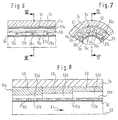
- Figures 6 and 7 show details of an inventive Separating device itself of the separation devices explained above distinguishes that the filter body 9c on the support tube 11c supporting ribs 39c integrally formed on the separating body 9c are.
- the ribs 39c again run essentially in the circumferential direction and preferably helical around the otherwise tubular filter body 9c and also delimit between them approximately in the circumferential direction extending grooves 27c.
- the support tube 11c contains a large number distributed in its wall in the circumferential direction axial bores 53c that extend radially inward axially extending, opening to the inner jacket of the support tube 11c Overlap slots 55.
- the slots which are essentially extend over the entire length of the bores 53c have a width in the circumferential direction and a radial one Towards a depth that is less than the diameter of holes 53c. This leaves between in the circumferential direction adjacent slots 55 comparatively wide foot areas 57 for radial support of the ribs 39c of the filter body 9c.
- the support tube 11c has one smooth-faced, cylindrical outer jacket with which it in turn supported on the inner jacket 5c of the housing tube 7c is.
- those indicated at 15c have Filter holes of the filter body 9c expediently a shape that widens radially outwards.
- the bores 53c can widen conically Cross section. Because such a cross-section increases manufacturing costs requires can be analogous to that shown in Figure 8 variant 1 that at least the support tube 11d from a plurality of axially adjoining pipe sections 59 exists, each taken individually axially constant cross-sectional design, while the diameter of the holes 53d in the material outflow direction 61 increases from section to section.
- the pipe sections 59 have the same inside diameter and the same outside diameter, during the clear distance of the holes 53d from Center 63 of each pipe section remains the same. To this The radial distance of each bore 53d from the inner jacket is of the support pipe 11d is the same for each pipe section 59.
- the pipe sections 59 sit together in a housing pipe 7d and together support an axially continuous Filter body 9d.
- this idea is used when applying a separation device according to the invention radial support of the filter body 9d on the pipe sections 59 in the on the basis of the figures 6 and 7 explained ways.
- housing tube may also be used 7d and the filter body 9d corresponding to the pipe sections 59 can be axially divided. All of the above with the help of the variants explained in FIGS. 6 to 8 Support tube, if necessary, an integral part of the housing tube be.
Landscapes
- Engineering & Computer Science (AREA)
- Mechanical Engineering (AREA)
- Chemical & Material Sciences (AREA)
- Chemical Kinetics & Catalysis (AREA)
- Environmental & Geological Engineering (AREA)
- Extrusion Moulding Of Plastics Or The Like (AREA)
- Separation, Recovery Or Treatment Of Waste Materials Containing Plastics (AREA)
- Processing Of Solid Wastes (AREA)
- Filtration Of Liquid (AREA)
Description
- Fig. 1
- einen teilweisen, schematischen Axiallängsschnitt durch eine Trennvorrichtung an der Erfindung; verwirklicht werden kann;
- Fig. 2
- einen Axialquerschnitt durch die Trennvorrichtung, gesehen entlang einer Linie II-II in Fig. 1;
- Fig. 3
- eine aufgebrochene Teilansicht der Vorrichtung, gesehen entlang einer Linie III-III in Fig. 1;
- Fig. 4
- einen Detailschnitt durch eine Filterkörper der Vorrichtung;
- Fig. 5
- einen Detailschnitt durch eine Variante des Filterkörpers;
- Fig. 6
- einen teilweisen, schematischen Axiallängsschnitt durch eine gemäß der Erfindung abgewandelte Trennvorrichtung nach Fig. 1, gesehen entlang einer Linie VI - VI in Fig. 7;
- Fig. 7
- einen teilweisen Axialquerschnitt durch die Trennvorrichtung, gesehen entlang einer Linie VII - VII in Fig. 6 und
- Fig. 8
- einen teilweisen, schematischen Axiallängsschnitt durch eine Variante der Trennvorrichtung nach Fig. 6.
Claims (8)
- Trennvorrichtung zum Trennen von Materialien unterschiedlicher Konsistenz, insbesondere zum Trennen von Thermoplastkunststoff-Feststoff-Gemischen oder Gemischen aus unterschiedlich schmelzbaren Kunststoffen, umfassend:ein Gehäuse (1, 7c),einen in einer angenähert zylindrischen Kammer (5c) des Gehäuses (1, 7c) angeordneten hohlzylindrischen Filterkörper (9c) aus einem rohrförmigen Materialstück mit den Filterkörper (9c) radial durchdringenden Filterlöchern (15c),einer in dem Gehäuse (1, 7c) gelagerten, gleichachsig zum Filterkörper (9c) drehend angetriebenen Schaberwelle (19), welche den Filterkörper (9c) unter Bildung eines Ringraums (25) axial durchsetzt und an ihrem Mantel wenigstens einen zum Filterkörper (9c) radial vorstehenden, federnd an dem Filterkörper (9c) anliegenden Schaber (21) trägt,eine das Materialgemisch unter Druck in den Ringraum (25) einführende Fördereinrichtung,den Filterkörper (9c) umschiießende Stützmittel (11c), die den Filterkörper (9c) über Stützrippen (39c) radial abstützen und die eine Vielzahl über den Umfang des Filterkörpers (9c) verteilte, angenähert axial verlaufende, erste Kanalabschnitte (53c) sowie zwischen den Stützrippen (39c) gelegene, quer zu den ersten Kanalabschnitten (53c) verlaufende zweite Kanalabschnitte (27c) bilden, wobei die Stützrippen (39c) einstückig an dem Filterkörper (9c) angeformt sind und die ersten Kanalabschnitte (53c) in einem Stützrohr (11c) vorgesehen sind, in welchem der Filterkörper (9c) koaxial sitzt,einen über die ersten (53c) und die zweiten (27c) Kanalabschnitte mit der Außenseite des Filterkörpers (9c) verbundenen, ersten Materialauslaß (31), undeinen mit der Innenseite des Filterkörpers (9c) verbundenen, zweiten Materialauslaß (33) mit Rückstaueigenschaft,
dadurch gekennzeichnet,
daß die ersten Kanalabschnitte durch im wesentlichen axiale, in der Wand des Stützrohrs (11c) verlaufende Bohrungen (53c) gebildet sind, von denen jede durch einen längs der Bohrung (53c) sich erstreckenden Schlitz (55) mit der Innenseite des Stützrohrs (11c) verbunden ist und daß der Durchmesser jeder Bohrung (53c) größer als die Breite des zugehörigen Schlitzes (55) ist. - Trennvorrichtung nach Anspruch 1,
dadurch gekennzeichnet,
daß sich die Filterlöcher (15c) vom Inneren des Filterkörpers (9c) her nach außen erweitern, insbesondere konisch oder stufenförmig erweitern. - Trennvorrichtung nach Anspruch 1 oder 2,
dadurch gekennzeichnet,
daß die zweiten Kanalabschnitte (27c) in Form wenigstens einer Schraubenwendel angeordnet sind. - Trennvorrichtung nach einem der Ansprüche 1 bis 3,
dadurch gekennzeichnet,
daß das Stützrohr (11d) aus mehreren gleichachsig hintereinander angeordneten, von einander separierbaren Rohrabschnitten (59) mit gleichem Innendurchmesser zusammengesetzt ist, und daß sich die ersten Kanalabschnitte (53d) durch die Rohrabschnitte (59) hindurcherstrecken und in den einzelnen Rohrabschnitten (59) eine längs des Rohrabschnitts (59) im wesentlichen gleichbleibende, von Rohrabschnitt (59) zu Rohrabschnitt (59) zum ersten Materialauslaß (31) hin jedoch zunehmende Querschnittsfläche haben. - Trennvorrichtung nach Anspruch 4,
dadurch gekennzeichnet,
daß die ersten Kanalabschnitte (53d) als Bohrungen ausgebildet sind, deren Durchmesser von Rohrabschnitt (59) zu Rohrabschnitt (59) zum ersten Materialauslaß (31) zunimmt. - Trennvorrichtung nach Anspruch 5,
dadurch gekennzeichnet,
daß die Bohrungen (53d) benachbarter Rohrabschnitte (59) gegeneinander radial versetzt sind und im wesentlichen gleichen lichten Abstand vom Zentrum (61) des Stützrohrs (11d) haben. - Trennvorrichtung nach einem der Ansprüche 1 bis 6,
dadurch gekennzeichnet,
daß der Filterkörper (9) an einem Ende, insbesondere am Materialzuführende, einen radial nach außen abstehenden Flansch (47) aufweist mit dem er drehfest am Gehäuse (1, 7) fixiert ist. - Trennvorrichtung nach Anspruch 7,
dadurch gekennzeichnet,
daß der Flansch (47) in Klemmsitz zwischen einem Gehäuseteil (1) und dem Stützrohr (11) eingespannt ist.
Applications Claiming Priority (2)
| Application Number | Priority Date | Filing Date | Title |
|---|---|---|---|
| DE19934308685 DE4308685C2 (de) | 1992-10-15 | 1993-03-18 | Trennvorrichtung zum Trennen von Materialien unterschiedlicher Konsistenz |
| DE4308685 | 1993-03-18 |
Publications (2)
| Publication Number | Publication Date |
|---|---|
| EP0615829A1 EP0615829A1 (de) | 1994-09-21 |
| EP0615829B1 true EP0615829B1 (de) | 1998-06-17 |
Family
ID=6483157
Family Applications (1)
| Application Number | Title | Priority Date | Filing Date |
|---|---|---|---|
| EP19940103960 Expired - Lifetime EP0615829B1 (de) | 1993-03-18 | 1994-03-15 | Trennvorrichtung |
Country Status (2)
| Country | Link |
|---|---|
| EP (1) | EP0615829B1 (de) |
| AT (1) | ATE167423T1 (de) |
Families Citing this family (6)
| Publication number | Priority date | Publication date | Assignee | Title |
|---|---|---|---|---|
| DE19704621A1 (de) | 1997-01-14 | 1998-09-24 | Josef Gail | Vorrichtung zum Reinigen viskosen Materials |
| DE20319752U1 (de) * | 2003-12-20 | 2005-05-12 | Ettlinger Kunststoffmaschinen Gmbh | Vorrichtung zum kontinuierlichen Filtern von Materialgemischen |
| CN106731175B (zh) * | 2016-12-13 | 2024-03-22 | 博敏电子股份有限公司 | 一种沉铜线除胶渣槽复合过滤装置及其使用方法 |
| CN114770882B (zh) * | 2022-03-23 | 2023-04-28 | 绍兴博越塑业科技有限公司 | 一种用于绣花机面板加工的环保型注塑成型机 |
| CN119367834B (zh) * | 2024-12-27 | 2025-04-01 | 湖南省十月花茶油有限公司 | 一种用于茶油生产用的茶油过滤设备 |
| CN119838284A (zh) * | 2025-03-11 | 2025-04-18 | 扬州大学 | 一种污水处理用微滤机 |
Family Cites Families (4)
| Publication number | Priority date | Publication date | Assignee | Title |
|---|---|---|---|---|
| US4470904A (en) * | 1981-10-28 | 1984-09-11 | Josef Gail | Mechanism for separating materials of varying consistency |
| DE3505667A1 (de) * | 1985-02-19 | 1986-08-28 | Eberhard 7760 Radolfzell Bücheler | Regeneriervorrichtung zur gewinnung von metallischen verunreinigungen aus geschmolzenem kunststoff |
| EP0411163B1 (de) * | 1989-07-06 | 1994-03-16 | Evgeny Petrovich Barmashin | Filtervorrichtung mit kontinuierlicher Reinigung der Filterfläche |
| DE9216390U1 (de) * | 1992-12-02 | 1993-01-28 | Rainer Huber GmbH, 7831 Malterdingen | Siebvorrichtung für eine Spritzgieß- oder Extrudiereinheit |
-
1994
- 1994-03-15 AT AT94103960T patent/ATE167423T1/de not_active IP Right Cessation
- 1994-03-15 EP EP19940103960 patent/EP0615829B1/de not_active Expired - Lifetime
Also Published As
| Publication number | Publication date |
|---|---|
| EP0615829A1 (de) | 1994-09-21 |
| ATE167423T1 (de) | 1998-07-15 |
Similar Documents
| Publication | Publication Date | Title |
|---|---|---|
| EP1519823B1 (de) | Vorrichtung zum kontinuierlichen filtern von materialgemischen | |
| DE4392041C1 (de) | Schneckenpresse | |
| EP0625925B1 (de) | Filtriervorrichtung für verunreinigte kunststoffschmelzen | |
| EP0078064B1 (de) | Vorrichtung zum Trennen von Materialien unterschiedlicher Konsistenz | |
| EP0751254B1 (de) | Vorrichtung zur geregelten Dispergierbehandlung von hochkonsistentem Faserstoff | |
| DE1944642A1 (de) | Schneckenpresse | |
| DE68917150T2 (de) | Siebanordnung. | |
| DE3340734C2 (de) | Schnecke einer Schneckenpresse | |
| DE2634160A1 (de) | Einrichtung zum entgasen plastischer stoffe | |
| EP0504836B1 (de) | Rührwerksmühle | |
| DE3047314A1 (de) | Vorrichtung zum mischen, dispergieren und homogenisieren von massen mit mindestens einer viskosen komponente | |
| EP0615829B1 (de) | Trennvorrichtung | |
| DE4308685C2 (de) | Trennvorrichtung zum Trennen von Materialien unterschiedlicher Konsistenz | |
| DE3941505C1 (de) | ||
| WO2023222378A1 (de) | Filteranordnung | |
| DE2913457A1 (de) | Umlaufende pressvorrichtung zum kontinuierlichen auspressen oelhaltiger samen und fruechte | |
| EP1038606B1 (de) | Verfahren zur Herstellung eines Getriebeteils | |
| EP0012795B1 (de) | Schneckenstrangpresse für die Verarbeitung von Kunststoff, Kautschuk oder dergleichen | |
| AT395325B (de) | Vorrichtung zum auftrennen einer zellulosefaserbrei-suspension | |
| EP0571750B1 (de) | Schneckenpresse | |
| EP0160782B1 (de) | Vorrichtung zum Trennen von Materialien unterschiedlicher Konsistenz | |
| DE20210115U1 (de) | Vorrichtung zum kontinuierlichen Filtern von Materialgemischen | |
| DE4029139C2 (de) | ||
| DE3819240A1 (de) | Dornhonwerkzeug | |
| DE60011819T2 (de) | Extrusionsdüse zum blasformen |
Legal Events
| Date | Code | Title | Description |
|---|---|---|---|
| PUAI | Public reference made under article 153(3) epc to a published international application that has entered the european phase |
Free format text: ORIGINAL CODE: 0009012 |
|
| AK | Designated contracting states |
Kind code of ref document: A1 Designated state(s): AT ES FR GB IT SE |
|
| K1C1 | Correction of patent application (title page) published |
Effective date: 19940921 |
|
| 17P | Request for examination filed |
Effective date: 19950309 |
|
| 17Q | First examination report despatched |
Effective date: 19960619 |
|
| GRAG | Despatch of communication of intention to grant |
Free format text: ORIGINAL CODE: EPIDOS AGRA |
|
| GRAG | Despatch of communication of intention to grant |
Free format text: ORIGINAL CODE: EPIDOS AGRA |
|
| GRAH | Despatch of communication of intention to grant a patent |
Free format text: ORIGINAL CODE: EPIDOS IGRA |
|
| GRAH | Despatch of communication of intention to grant a patent |
Free format text: ORIGINAL CODE: EPIDOS IGRA |
|
| GRAA | (expected) grant |
Free format text: ORIGINAL CODE: 0009210 |
|
| AK | Designated contracting states |
Kind code of ref document: B1 Designated state(s): AT ES FR GB IT SE |
|
| PG25 | Lapsed in a contracting state [announced via postgrant information from national office to epo] |
Ref country code: ES Free format text: THE PATENT HAS BEEN ANNULLED BY A DECISION OF A NATIONAL AUTHORITY Effective date: 19980617 |
|
| REF | Corresponds to: |
Ref document number: 167423 Country of ref document: AT Date of ref document: 19980715 Kind code of ref document: T |
|
| ITF | It: translation for a ep patent filed | ||
| GBT | Gb: translation of ep patent filed (gb section 77(6)(a)/1977) |
Effective date: 19980618 |
|
| PG25 | Lapsed in a contracting state [announced via postgrant information from national office to epo] |
Ref country code: SE Free format text: LAPSE BECAUSE OF FAILURE TO SUBMIT A TRANSLATION OF THE DESCRIPTION OR TO PAY THE FEE WITHIN THE PRESCRIBED TIME-LIMIT Effective date: 19980917 |
|
| ET | Fr: translation filed | ||
| PLBE | No opposition filed within time limit |
Free format text: ORIGINAL CODE: 0009261 |
|
| STAA | Information on the status of an ep patent application or granted ep patent |
Free format text: STATUS: NO OPPOSITION FILED WITHIN TIME LIMIT |
|
| 26N | No opposition filed | ||
| PGFP | Annual fee paid to national office [announced via postgrant information from national office to epo] |
Ref country code: GB Payment date: 20010305 Year of fee payment: 8 |
|
| PGFP | Annual fee paid to national office [announced via postgrant information from national office to epo] |
Ref country code: FR Payment date: 20010315 Year of fee payment: 8 |
|
| REG | Reference to a national code |
Ref country code: GB Ref legal event code: IF02 |
|
| PGFP | Annual fee paid to national office [announced via postgrant information from national office to epo] |
Ref country code: AT Payment date: 20020118 Year of fee payment: 9 |
|
| PG25 | Lapsed in a contracting state [announced via postgrant information from national office to epo] |
Ref country code: GB Free format text: LAPSE BECAUSE OF NON-PAYMENT OF DUE FEES Effective date: 20020315 |
|
| GBPC | Gb: european patent ceased through non-payment of renewal fee |
Effective date: 20020315 |
|
| PG25 | Lapsed in a contracting state [announced via postgrant information from national office to epo] |
Ref country code: FR Free format text: LAPSE BECAUSE OF NON-PAYMENT OF DUE FEES Effective date: 20021129 |
|
| REG | Reference to a national code |
Ref country code: FR Ref legal event code: ST |
|
| PG25 | Lapsed in a contracting state [announced via postgrant information from national office to epo] |
Ref country code: AT Free format text: LAPSE BECAUSE OF NON-PAYMENT OF DUE FEES Effective date: 20030315 |
|
| PG25 | Lapsed in a contracting state [announced via postgrant information from national office to epo] |
Ref country code: IT Free format text: LAPSE BECAUSE OF NON-PAYMENT OF DUE FEES;WARNING: LAPSES OF ITALIAN PATENTS WITH EFFECTIVE DATE BEFORE 2007 MAY HAVE OCCURRED AT ANY TIME BEFORE 2007. THE CORRECT EFFECTIVE DATE MAY BE DIFFERENT FROM THE ONE RECORDED. Effective date: 20050315 |