EP0615702A2 - Verfahren und Vorrichtung zur Herstellung von mit Bändern versehene Umhüllungen für Rauchartikeln - Google Patents
Verfahren und Vorrichtung zur Herstellung von mit Bändern versehene Umhüllungen für Rauchartikeln Download PDFInfo
- Publication number
- EP0615702A2 EP0615702A2 EP94301850A EP94301850A EP0615702A2 EP 0615702 A2 EP0615702 A2 EP 0615702A2 EP 94301850 A EP94301850 A EP 94301850A EP 94301850 A EP94301850 A EP 94301850A EP 0615702 A2 EP0615702 A2 EP 0615702A2
- Authority
- EP
- European Patent Office
- Prior art keywords
- mesh
- substrate
- paper
- regions
- fluidized material
- Prior art date
- Legal status (The legal status is an assumption and is not a legal conclusion. Google has not performed a legal analysis and makes no representation as to the accuracy of the status listed.)
- Granted
Links
Images


Classifications
-
- A—HUMAN NECESSITIES
- A24—TOBACCO; CIGARS; CIGARETTES; SIMULATED SMOKING DEVICES; SMOKERS' REQUISITES
- A24D—CIGARS; CIGARETTES; TOBACCO SMOKE FILTERS; MOUTHPIECES OF CIGARS OR CIGARETTES; MANUFACTURE OF TOBACCO SMOKE FILTERS OR MOUTHPIECES
- A24D1/00—Cigars; Cigarettes
- A24D1/02—Cigars; Cigarettes with special covers
- A24D1/025—Cigars; Cigarettes with special covers the covers having material applied to defined areas, e.g. bands for reducing the ignition propensity
-
- D—TEXTILES; PAPER
- D21—PAPER-MAKING; PRODUCTION OF CELLULOSE
- D21F—PAPER-MAKING MACHINES; METHODS OF PRODUCING PAPER THEREON
- D21F11/00—Processes for making continuous lengths of paper, or of cardboard, or of wet web for fibre board production, on paper-making machines
- D21F11/006—Making patterned paper
Definitions
- This invention relates to a method and apparatus for making banded smoking article wrappers. More particularly, the invention relates to a method and apparatus for applying cellulosic slurry in repetitive patterns to paper for making banded smoking article wrappers.
- Smoking article manufacturers have long appreciated the usefulness of adding flavorings or burn control additives to smoking article paper. More recently, it has been recognized that smoking article paper could be altered so that smoking articles incorporating the altered paper will have a reduced burn rate when the smoking article is not drawn on by a smoker.
- Paper smoking article wrappers have burn characteristics, including burn rates and static burn capabilities. It is known that burn characteristics can be modified by adding fillers, coatings, or other additives to papers. Copending, commonly-assigned United States patent application Serial No. 07/614,620, filed November 16, 1990 includes a description of many of these methods, and also discloses a nonlaminated paper of variable basis weight having modified burn rate characteristics. The methods and apparatus disclosed in that application, however, are not the only solutions for making banded smoking article wrappers with modified burn rate characteristics.
- a method of applying a fluidized material e.g., a cellulosic slurry
- a substrate e.g., a continuous web of smoking article wrapper paper
- the method includes the steps of: (a) moving the substrate along a path; (b) providing a cylindrical surface having alternating regions of mesh material separated by regions of solid material; (c) applying the fluidized material to the cylindrical surface; (d) providing a vacuum on an underside of the mesh material so as to allow the fluidized material to adhere to the alternating regions of mesh material; (e) rotating said cylindrical surface so that the adhered fluidized material is positioned adjacent the substrate; and (f) providing pressure on the underside of the mesh material to release the adhered fluidized material from the mesh material, wherein the released fluidized material attaches to the substrate.
- the substrate can then be formed in smoking article wrappers having repetitive regions of increased basis weight which modify the burn rate characteristics of a smoking article.
- an apparatus for making banded smoking article wrappers are also provided.
- the present invention relates to a method and apparatus for modifying the characteristics of paper by applying repetitive patterns of fluidized material to the paper. More particularly, the present invention relates to a method and apparatus for modifying the basis weight of smoking article paper in select regions so that the burn rate characteristics are modified in those regions.
- An increase in basis weight of localized regions in a paper web may be achieved by increasing either the thickness, the density, or both in those regions.
- the increase in basis weight may be accomplished by depositing, onto an existing pulp web in a papermaking machine, additional fluidized material (e.g., cellulosic pulp), or a filler material, or combinations thereof.
- additional fluidized material e.g., cellulosic pulp
- filler material e.g., cellulosic pulp
- the modified regions of the paper made in accordance with this invention have a basis weight above that of the underlying base web.
- the smoking article will have modified burn rate characteristics.
- the static burn rate of the smoking article may be substantially decreased during combustion of the modified regions, because regions of increased basis weight have decreased porosity. The rate of oxygen diffusion through the paper in these regions is thereby decreased, retarding combustion of the smoking article.
- the dimensions of the modified regions may also affect the burn characteristics of the paper and, consequently, a smoking article incorporating the paper.
- the modified regions form a series of rings of known width and separation along the longitudinal axis of the smoking article. Both the width of, and the amount of separation between, these rings of modified paper have a substantial effect on the overall burn rate of the smoking article. The width and amount of separation of the rings effectively determines what percentage of the smoking article will experience a burn rate decreased from the nominal rate associated with the base web.
- FIG. 1 depicts the pulp web-forming area of a conventional Fourdrinier papermaking machine modified in accordance with the present invention to produce banded smoking article wrappers.
- Applicator 40 is used to apply repetitive patterns of fluidized material, e.g., a slurry of cellulosic pulp, to pulp web 21 so as to repetitively increase the basis weight of the pulp web to provide banded smoking article wrapper paper.
- fluidized material e.g., a slurry of cellulosic pulp
- Headbox 22 contains a quantity of cellulosic pulp which is used to form pulp web 21. Pulp is supplied to headbox 22 by plurality of conduits 23 which communicate with a pulp source, such as a pulp storage tank (not shown). Immediately below headbox 22 is an endless forming wire 24. A slice 25 defined in a lower portion of headbox 22 adjacent to wire 24 permits the pulp from the headbox 22 to flow through slice 25 onto the top surface of the wire 24 to form pulp web 21. Slice 25 is usually narrow in height in order to regulate the amount of pulp which flows from headbox 22. Slice 25 typically may extend substantially across the entire width of pulp web 21.
- the top portion of wire 24 is adapted to move forwardly toward couch roll 26 and away from slice 25.
- the direction from headbox 22 toward couch roll 26 is 35 defined as the downstream direction.
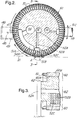
- applicator 40 includes slurry coater 46 and screen roller 60 which rotates around fixed valve 62.
- Fixed valve 62 includes pressure port 52, vacuum port 54 and cleaning injection port 56.
- Applicator 4.0 works as follows.
- Slurry is applied to surface 51 of screen roller 60 using slurry coater 46.
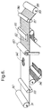
- Surface 51 of screen roller 60 includes alternating regions of screen sections 64 separated by spacers 66 (see FIGS. 4 and 5).
- Vacuum port 54 connected to vacuum 45 (FIG. 1), is used to hold the coated slurry only on screen sections 64 and not on spacers 66. Because screen sections 64 become coated with slurry, while spacers 66 do not, a repetitive pattern of slurry is formed on surface 51 of screen roller 60 in region 51A adjacent vacuum port 54. This pattern is applied to pulp web 21 in region 51B so as to form bands of increased basis weight.
- Slurry coater 46 includes slurry supply 47, doctor blade 48 and slurry return 49.
- Slurry supply 47 connected to slurry reservoir 42 (FIG. 1), applies a continuous thin layer of slurry to surface 51 of screen roller 60.
- Slurry adheres to surface 51 of screen roller 60 with the aid of vacuum port 54 which pulls the slurry towards screen sections 64 (FIG. 4).
- Screen sections 64 are preferably made from the same type of screen material used in conventional paper making (e.g., wire 24 in FIG. 1), so as to allow slurry to adhere to surface 51 by way of the vacuum force provided by vacuum port 54.
- screen sections 64 preferably have a mesh size of approximately 100, with openings of approximately 0.15 mm by 0.15 mm (5.9 mils by 5.9 mils).
- Screen sections 64 in conjunction with spacers 66 (FIG. 4), define a recess 65 which contains the slurry that is eventually transferred to pulp web 21 upon further rotation of screen roller 60.
- Doctor blade 48 of slurry coater 46 assists in removing excess slurry from surface 51 of screen roller 60 so that the slurry is confined to recesses 65 of rotating screen 60 so as to not cover spacers 66.
- Slurry return 49 of slurry coater 46 recovers excess slurry removed from rotating screen 60.
- the spacing 67 between adjacent spacers 66 determines the width of recesses 65 and, therefore, the width of the "band" of slurry applied to pulp web 21.
- the thickness 67A associated with spacers 66 determines the thickness of the "band” of slurry applied to pulp web 21.
- Width 66A of spacers 66 determines the spacing between bands.
- spacing 67 ranges from 2 to 8 mm
- thickness 67A ranges from about 0.3 mm to 0.8 mm (0.01 to 0.03 inch)
- width 66A ranges from about 12 to 20 mm. More preferably, spacing 67 is about 5 mm, thickness 67A is about 0.38 mm (0.015 inch) and width 66A is about 16 mm.
- spacing 67 is about 5 mm
- thickness 67A is about 0.38 mm (0.015 inch)
- width 66A is about 16 mm.
- many other dimensions are possible by replacing spacers 66 with spacers of different dimensions or by altering the number of recesses 65 per circumference of applicator 40.
- Vacuum cleaning port 58 is used to assist in the cleaning process by pulling the air and water mixture through screen 67 into vacuum cleaning port 58.
- screen roller 60 rotates around fixed valve 62 by way of drive 61 positioned on one or both ends of screen roller 60.
- Drive 61 causes screen roller 60 to rotate at a speed substantially synchronized with moving web 21.
- the spacing between the bands of slurry applied to web 21 will be determined by spacing 67 (FIG. 3) on screen roller 60.
- applicator 40 is spaced above pulp web 21 so that spacers 66 do not make substantial contact with pulp web 21.
- pressure port 52 includes pressure supply region 52A, plurality of radial channels 52B and pressure slot 52C.
- air is supplied to pressure supply region 52A at the center of fixed valve 62 by way of air compressor 41 (FIG. 1). If desired, any other means which can supply air at a pressure above 1 atmosphere can also be used.
- Radial channels 52B provide air flow communication between pressure supply region 52A and pressure slot 52C .
- Pressure slot 52C is shaped to allow the slurry to release from screen sections 64 when a slurry-coated rotating screen 60 rotates into position 51B.
- pressure port 52 could be used with pressure port 52 to assist in forcing the slurry to release from screen sections 64 when rotating screen 60 rotates from position 51A into 35 position 51B.
- radial channels 52B are shown in FIG. 2 as forming approximately a 90° angle with the underlying pulp web 21, it is apparent that this angle can be changed by rotating fixed valve 62 relative to screen roller 60. This feature of the present invention can be used to accurately adjust the deposit point of slurry onto the underlying pulp web.
- rotating screen 60 includes closely-pitched radial holes 72 and continuous slots 74 which provides air flow communication between inside surface 60A of screen roller 60 (FIG. 3) and screen sections 64.
- Continuous slots 74 are individually covered with screen sections 76.
- Spacers 66 which run from end 40A to end 40B of applicator 40, hold down screen sections 76 and are removably attached to rotating screen 60 by way of screws 78.
- Screw heads 78A are preferably filled with a potting material (not shown) in order to provide a surface which is substantially flat and flush with surfaces 79 of spacers 66.
- Individual spacers 66 are removable from applicator 40, by way of screws 78, so as to allow individual screen sections 76 to be conveniently replaced.
- spacers 66 could be held in place by way of screws (not shown) which attach to the inside surface 66A of spacers 66 through holes provided from inside surface 60B (see FIG. 3) of screen roller 60 instead of outside surface 60A.
- bands 81 are substantially rectangular, corresponding to the shape of recesses 65 (FIGS. 4 and 5) of applicator 40.
- These bands 81 preferably are substantially parallel to one another and equally spaced and form application pattern 82 which alters the characteristics of the pulp web 21.
- pulp web 21 is delivered from wire 24 to a plurality of press rolls 27 and then to a conventional dryer section (not shown) of papermaking machine. As pulp web 21 advances in the downstream direction, excess water is permitted to pass through wire 24.
- a vacuum 28 typically may be applied to at least a portion of the underside of wire 24 to assist in the removal of water from pulp web 21. Vacuum 28 also facilitates the penetration of deposited slurry into pulp web 21.
- couch roll 26 may be adapted to provide a vacuum through wire 24 to the underside of pulp web 21 to remove additional water.
- the paper produced by the apparatus of the present invention shown in FIGS. 1-5 can then be used to wrap around tobacco material so as to form continuous rods of smoking article material.
- the continuous rods can then be periodically severed so as to form individual smoking articles that have modified burn rate characteristics.
- applicator 40 has been incorporated in a machine to modify premanufactured paper (in a configuration commonly referred to as "off-line", as opposed to the "on-line” configuration shown in FIG. 1).
- the machine has a roll of premanufactured paper 90 mounted on feedshaft 91.
- the paper on roll 90 is fed between upper idler 92 and lower idler 93 and onto a continuous moving web 94.
- a continuous moving web may not be needed, depending on paper strength.
- the paper may be supported by a shoe (not shown) familiar to those skilled in the art.
- Applicator 40 is mounted above the continuous moving web 94 which is supporting the paper 90 to be treated.
- the paper moves underneath dryer 95.
- dryer 95 A number of types of dryers means familiar to those skilled in the art including felt absorption, heated drums and infrared drying may be used.
- the paper moves between final upper idler 96 and final lower idler 97. Paper 90 is then taken up by take-up roll 98 mounted on take-up shaft 99.
- premanufactured paper 90 mounted on feedshaft 91, it will be apparent that premanufactured paper 90, in the alternative, could be supplied on-line directly from a paper making apparatus.
- coater 46 could apply the types of fibrous cellulose which are described in copending, commonly-assigned United States patent application Serial No. 07/757,243, filed September 10, 1991, which is hereby incorporated by reference in its entirety. Any other type of material that can be coated onto an underlying paper web could also be used with coater 46.
- the present invention could also be used to apply a pattern of tobacco flavor material, or a pattern of electrically conductive, resistive or insulating material, for use in electrical smoking flavor generating articles such as those disclosed in commonly-assigned U.S. Patent No. 5,060,671.
- the invention could be used to treat substrates other than paper. Although the preferred embodiments discussed above relate to smoking article paper, it will be apparent that the invention has many applications.
Landscapes
- Cigarettes, Filters, And Manufacturing Of Filters (AREA)
- Paper (AREA)
- Auxiliary Devices For And Details Of Packaging Control (AREA)
- Peptides Or Proteins (AREA)
Applications Claiming Priority (2)
| Application Number | Priority Date | Filing Date | Title |
|---|---|---|---|
| US08/031,946 US5342484A (en) | 1993-03-16 | 1993-03-16 | Method and apparatus for making banded smoking article wrappers |
| US31946 | 1993-03-16 |
Publications (3)
| Publication Number | Publication Date |
|---|---|
| EP0615702A2 true EP0615702A2 (de) | 1994-09-21 |
| EP0615702A3 EP0615702A3 (de) | 1994-11-02 |
| EP0615702B1 EP0615702B1 (de) | 1999-05-26 |
Family
ID=21862245
Family Applications (1)
| Application Number | Title | Priority Date | Filing Date |
|---|---|---|---|
| EP94301850A Expired - Lifetime EP0615702B1 (de) | 1993-03-16 | 1994-03-15 | Verfahren und Vorrichtung zur Herstellung von mit Bändern versehenen Umhüllungen |
Country Status (8)
| Country | Link |
|---|---|
| US (1) | US5342484A (de) |
| EP (1) | EP0615702B1 (de) |
| JP (1) | JPH06316898A (de) |
| AT (1) | ATE180390T1 (de) |
| DE (1) | DE69418637T2 (de) |
| DK (1) | DK0615702T3 (de) |
| ES (1) | ES2132338T3 (de) |
| GR (1) | GR3030634T3 (de) |
Families Citing this family (34)
| Publication number | Priority date | Publication date | Assignee | Title |
|---|---|---|---|---|
| US6645605B2 (en) | 2001-01-15 | 2003-11-11 | James Rodney Hammersmith | Materials and method of making same for low ignition propensity products |
| US20020179105A1 (en) * | 2001-02-26 | 2002-12-05 | Zawadzki Michael A. | Reduced ignition propensity smoking article |
| US20020179106A1 (en) * | 2001-03-28 | 2002-12-05 | Zawadzki Michael A. | Reduced ignition propensity smoking article with a polysaccharide treated wrapper |
| US7275548B2 (en) * | 2001-06-27 | 2007-10-02 | R.J. Reynolds Tobacco Company | Equipment for manufacturing cigarettes |
| US7448390B2 (en) * | 2003-05-16 | 2008-11-11 | R.J. Reynolds Tobacco Company | Equipment and methods for manufacturing cigarettes |
| US7073514B2 (en) * | 2002-12-20 | 2006-07-11 | R.J. Reynolds Tobacco Company | Equipment and methods for manufacturing cigarettes |
| US6854469B1 (en) | 2001-06-27 | 2005-02-15 | Lloyd Harmon Hancock | Method for producing a reduced ignition propensity smoking article |
| US20040238136A1 (en) * | 2003-05-16 | 2004-12-02 | Pankaj Patel | Materials and methods for manufacturing cigarettes |
| US6779530B2 (en) | 2002-01-23 | 2004-08-24 | Schweitzer-Mauduit International, Inc. | Smoking articles with reduced ignition proclivity characteristics |
| US7195019B2 (en) * | 2002-12-20 | 2007-03-27 | R. J. Reynolds Tobacco Company | Equipment for manufacturing cigarettes |
| US7281540B2 (en) | 2002-12-20 | 2007-10-16 | R.J. Reynolds Tobacco Company | Equipment and methods for manufacturing cigarettes |
| US7117871B2 (en) * | 2002-12-20 | 2006-10-10 | R.J. Reynolds Tobacco Company | Methods for manufacturing cigarettes |
| US7275549B2 (en) * | 2002-12-20 | 2007-10-02 | R.J. Reynolds Tobacco Company | Garniture web control |
| US7077145B2 (en) * | 2002-12-20 | 2006-07-18 | R.J. Reynolds Tobacco Company | Equipment and methods for manufacturing cigarettes |
| US7234471B2 (en) * | 2003-10-09 | 2007-06-26 | R. J. Reynolds Tobacco Company | Cigarette and wrapping materials therefor |
| US20040122547A1 (en) * | 2002-12-20 | 2004-06-24 | Seymour Sydney Keith | Equipment and methods for manufacturing cigarettes |
| US7276120B2 (en) * | 2003-05-16 | 2007-10-02 | R.J. Reynolds Tobacco Company | Materials and methods for manufacturing cigarettes |
| US7047982B2 (en) * | 2003-05-16 | 2006-05-23 | R.J. Reynolds Tobacco Company | Method for registering pattern location on cigarette wrapping material |
| AU2004253467B2 (en) * | 2003-06-13 | 2010-04-22 | Philip Morris Products S.A. | Cigarette wrapper with printed catalyst |
| AR045430A1 (es) * | 2003-06-13 | 2005-10-26 | Philip Morris Prod | Papel picado con rellenador catalitico en un rellenador de corte de tabaco y los metodos para fabricar el mismo |
| US7934510B2 (en) * | 2003-10-27 | 2011-05-03 | Philip Morris Usa Inc. | Cigarette wrapper with nanoparticle spinel ferrite catalyst and methods of making same |
| US8701681B2 (en) * | 2003-10-27 | 2014-04-22 | Philip Morris Usa Inc. | Use of oxyhydroxide compounds in cigarette paper for reducing carbon monoxide in the mainstream smoke of a cigarette |
| US8646463B2 (en) * | 2005-08-15 | 2014-02-11 | Philip Morris Usa Inc. | Gravure-printed, banded cigarette paper |
| US8925556B2 (en) | 2006-03-31 | 2015-01-06 | Philip Morris Usa Inc. | Banded papers, smoking articles and methods |
| US9255361B2 (en) * | 2006-03-31 | 2016-02-09 | Philip Morris Usa Inc. | In situ formation of catalytic cigarette paper |
| US7752995B2 (en) * | 2007-05-22 | 2010-07-13 | Johnson & Johnson Inc. | Slot-coating apparatus |
| US8701682B2 (en) | 2009-07-30 | 2014-04-22 | Philip Morris Usa Inc. | Banded paper, smoking article and method |
| RU2592017C2 (ru) | 2010-12-13 | 2016-07-20 | Алтриа Клайент Сервисез Ллс | Способ подготовки печатного раствора и получение сигаретной оберточной бумаги с рисунком |
| US10375988B2 (en) | 2010-12-13 | 2019-08-13 | Altria Client Services Llc | Cigarette wrapper with novel pattern |
| US11707082B2 (en) | 2010-12-13 | 2023-07-25 | Altria Client Services Llc | Process of preparing printing solution and making patterned cigarette wrapper |
| EP2709471A4 (de) | 2011-05-16 | 2015-05-27 | Altria Client Services Inc | Alternierende muster in zigarettenpapier sowie rauchartikel damit und verfahren dafür |
| CA2873781A1 (en) | 2012-05-16 | 2013-11-21 | Altria Client Services Inc. | Novel banded cigarette wrapper with opened area bands |
| WO2013173609A1 (en) | 2012-05-16 | 2013-11-21 | Altria Client Services Inc. | Cigarette wrapper with novel pattern |
| JP2016106182A (ja) * | 2013-03-19 | 2016-06-16 | 日本たばこ産業株式会社 | シガレット用巻紙 |
Family Cites Families (20)
| Publication number | Priority date | Publication date | Assignee | Title |
|---|---|---|---|---|
| US2728685A (en) * | 1952-01-17 | 1955-12-27 | Celotex Corp | Method of applying granules to simulate a masonry pattern |
| US2792780A (en) * | 1952-10-03 | 1957-05-21 | Carlyle W Jacob | Printing methods and apparatus |
| US3102046A (en) * | 1959-05-11 | 1963-08-27 | Us Envelope Co | Manufacture of pressure-sealing envelopes, bags, and the like |
| US3108560A (en) * | 1959-07-15 | 1963-10-29 | Gen Motors Corp | Means for assembling printed circuits with components |
| US3143065A (en) * | 1960-06-07 | 1964-08-04 | Russell C Warczak | Moistening apparatus and method for offset printing presses |
| IT1072364B (it) * | 1977-01-18 | 1985-04-10 | Rimar Meccania Spa | Tuno aspirante per l'estrazione di liquidi dai tessuti sottoposti a trattamenti di lavaggio,sbozzimatura o simili |
| US4209553A (en) * | 1977-08-23 | 1980-06-24 | Robert Greenberg | Method and apparatus for making material with a fusible backing |
| WO1980002852A1 (en) * | 1979-06-11 | 1980-12-24 | Tybar Eng Pty Ltd | Application of liquid utilising a controlled gas supply |
| DE3401588A1 (de) * | 1983-02-01 | 1984-08-02 | Molins PLC, London | Vorrichtung zum aufbringen von klebstoff |
| DE3309975A1 (de) * | 1983-03-19 | 1984-09-20 | Mathias 4815 Schloss Holte Mitter | Als schlitzrakel ausgebildete auftragsvorrichtung |
| US4604966A (en) * | 1985-10-10 | 1986-08-12 | International Business Machine Corp. | Continuous solder paste dispenser |
| EP0226939B1 (de) * | 1985-12-10 | 1992-11-19 | Kimberly-Clark Corporation | Vorrichtung und Verfahren für die Erzeugung eines Faservlieses |
| US4666647A (en) * | 1985-12-10 | 1987-05-19 | Kimberly-Clark Corporation | Apparatus and process for forming a laid fibrous web |
| US4680199A (en) * | 1986-03-21 | 1987-07-14 | United Technologies Corporation | Method for depositing a layer of abrasive material on a substrate |
| GB8916242D0 (en) * | 1989-07-14 | 1989-08-31 | Crompton J R Plc | Improvements in or relating to non-wovens |
| DE4020420A1 (de) * | 1990-06-27 | 1992-01-02 | Volker Ludwig | Verfahren zum auftragen von fluessigen, pastoesen oder plastischen substanzen auf ein substrat |
| EP0483998A1 (de) * | 1990-10-30 | 1992-05-06 | Philip Morris Products Inc. | Herstellungsverfahren von Umhüllung für Rauchartikel |
| DE69126277T2 (de) * | 1990-11-16 | 1997-12-04 | Philip Morris Prod | Papier mit veränderlichem Querquadratmetergewicht |
| US5263999A (en) * | 1991-09-10 | 1993-11-23 | Philip Morris Incorporated | Smoking article wrapper for controlling burn rate and method for making same |
| US5534114A (en) * | 1992-03-06 | 1996-07-09 | Philip Morris Incorporated | Method and apparatus for applying a material to a web |
-
1993
- 1993-03-16 US US08/031,946 patent/US5342484A/en not_active Expired - Fee Related
-
1994
- 1994-03-14 JP JP6069886A patent/JPH06316898A/ja active Pending
- 1994-03-15 AT AT94301850T patent/ATE180390T1/de not_active IP Right Cessation
- 1994-03-15 EP EP94301850A patent/EP0615702B1/de not_active Expired - Lifetime
- 1994-03-15 DE DE69418637T patent/DE69418637T2/de not_active Expired - Fee Related
- 1994-03-15 DK DK94301850T patent/DK0615702T3/da active
- 1994-03-15 ES ES94301850T patent/ES2132338T3/es not_active Expired - Lifetime
-
1999
- 1999-06-30 GR GR990401720T patent/GR3030634T3/el unknown
Also Published As
| Publication number | Publication date |
|---|---|
| ATE180390T1 (de) | 1999-06-15 |
| JPH06316898A (ja) | 1994-11-15 |
| GR3030634T3 (en) | 1999-10-29 |
| DK0615702T3 (da) | 1999-11-08 |
| ES2132338T3 (es) | 1999-08-16 |
| EP0615702B1 (de) | 1999-05-26 |
| DE69418637T2 (de) | 1999-12-02 |
| DE69418637D1 (de) | 1999-07-01 |
| US5342484A (en) | 1994-08-30 |
| EP0615702A3 (de) | 1994-11-02 |
Similar Documents
| Publication | Publication Date | Title |
|---|---|---|
| EP0615702B1 (de) | Verfahren und Vorrichtung zur Herstellung von mit Bändern versehenen Umhüllungen | |
| EP0559453B1 (de) | Verfahren und Vorrichtung zum Auftragen eines Materials auf eine Warenbahn | |
| US5360516A (en) | Application of fluidized material to a substrate using intermittent charges of compressed air | |
| FI98547C (fi) | Paperi, jossa on poikkisuuntaisia alueita, joiden neliömassa vaihtelee | |
| US5332472A (en) | Application of fluidized material to a substrate using displacement transfer | |
| CA1298079C (en) | Coating apparatus and method | |
| EP1877621A2 (de) | Verfahren und vorrichtung zum auftragen eines materials auf ein breites hochgeschwindigkeitsband | |
| US20170188625A1 (en) | Method and Apparatus For Making Slit-Banded Wrapper Using Moving Orifices | |
| EP0083197B1 (de) | Aufbau eines Mundstücks für stabförmige Rauchartikel | |
| US4089740A (en) | Apparatus for applying secondary layer on board surface | |
| EP0166189B1 (de) | Anordnung im Auffangkasten einer Rundsiebmaschine | |
| CA2122350C (en) | A pick-up roll apparatus | |
| CA2076588C (en) | Fluid jet supported headbox | |
| HK1002141B (en) | Method and apparatus for applying a material to a web | |
| FI80740B (fi) | Anordning foer formning av en pappersbana. | |
| JPH0724382A (ja) | ロールコータ |
Legal Events
| Date | Code | Title | Description |
|---|---|---|---|
| PUAI | Public reference made under article 153(3) epc to a published international application that has entered the european phase |
Free format text: ORIGINAL CODE: 0009012 |
|
| PUAL | Search report despatched |
Free format text: ORIGINAL CODE: 0009013 |
|
| AK | Designated contracting states |
Kind code of ref document: A2 Designated state(s): AT BE CH DE DK ES FR GB GR IE IT LI LU MC NL PT SE |
|
| AK | Designated contracting states |
Kind code of ref document: A3 Designated state(s): AT BE CH DE DK ES FR GB GR IE IT LI LU MC NL PT SE |
|
| 17P | Request for examination filed |
Effective date: 19950406 |
|
| 17Q | First examination report despatched |
Effective date: 19970606 |
|
| GRAG | Despatch of communication of intention to grant |
Free format text: ORIGINAL CODE: EPIDOS AGRA |
|
| GRAG | Despatch of communication of intention to grant |
Free format text: ORIGINAL CODE: EPIDOS AGRA |
|
| GRAH | Despatch of communication of intention to grant a patent |
Free format text: ORIGINAL CODE: EPIDOS IGRA |
|
| GRAH | Despatch of communication of intention to grant a patent |
Free format text: ORIGINAL CODE: EPIDOS IGRA |
|
| GRAA | (expected) grant |
Free format text: ORIGINAL CODE: 0009210 |
|
| AK | Designated contracting states |
Kind code of ref document: B1 Designated state(s): AT BE CH DE DK ES FR GB GR IE IT LI LU MC NL PT SE |
|
| REF | Corresponds to: |
Ref document number: 180390 Country of ref document: AT Date of ref document: 19990615 Kind code of ref document: T |
|
| REG | Reference to a national code |
Ref country code: CH Ref legal event code: EP |
|
| REF | Corresponds to: |
Ref document number: 69418637 Country of ref document: DE Date of ref document: 19990701 |
|
| REG | Reference to a national code |
Ref country code: CH Ref legal event code: NV Representative=s name: BOVARD AG PATENTANWAELTE |
|
| REG | Reference to a national code |
Ref country code: IE Ref legal event code: FG4D |
|
| ET | Fr: translation filed | ||
| ITF | It: translation for a ep patent filed | ||
| REG | Reference to a national code |
Ref country code: ES Ref legal event code: FG2A Ref document number: 2132338 Country of ref document: ES Kind code of ref document: T3 |
|
| REG | Reference to a national code |
Ref country code: PT Ref legal event code: SC4A Free format text: AVAILABILITY OF NATIONAL TRANSLATION Effective date: 19990615 |
|
| REG | Reference to a national code |
Ref country code: DK Ref legal event code: T3 |
|
| PLBE | No opposition filed within time limit |
Free format text: ORIGINAL CODE: 0009261 |
|
| STAA | Information on the status of an ep patent application or granted ep patent |
Free format text: STATUS: NO OPPOSITION FILED WITHIN TIME LIMIT |
|
| 26N | No opposition filed | ||
| REG | Reference to a national code |
Ref country code: GB Ref legal event code: IF02 |
|
| PGFP | Annual fee paid to national office [announced via postgrant information from national office to epo] |
Ref country code: DK Payment date: 20040123 Year of fee payment: 11 |
|
| PGFP | Annual fee paid to national office [announced via postgrant information from national office to epo] |
Ref country code: AT Payment date: 20040205 Year of fee payment: 11 |
|
| PGFP | Annual fee paid to national office [announced via postgrant information from national office to epo] |
Ref country code: FR Payment date: 20040209 Year of fee payment: 11 |
|
| PGFP | Annual fee paid to national office [announced via postgrant information from national office to epo] |
Ref country code: GB Payment date: 20040212 Year of fee payment: 11 |
|
| PGFP | Annual fee paid to national office [announced via postgrant information from national office to epo] |
Ref country code: CH Payment date: 20040213 Year of fee payment: 11 |
|
| PGFP | Annual fee paid to national office [announced via postgrant information from national office to epo] |
Ref country code: PT Payment date: 20040217 Year of fee payment: 11 Ref country code: NL Payment date: 20040217 Year of fee payment: 11 |
|
| PGFP | Annual fee paid to national office [announced via postgrant information from national office to epo] |
Ref country code: IE Payment date: 20040218 Year of fee payment: 11 |
|
| PGFP | Annual fee paid to national office [announced via postgrant information from national office to epo] |
Ref country code: SE Payment date: 20040219 Year of fee payment: 11 |
|
| PGFP | Annual fee paid to national office [announced via postgrant information from national office to epo] |
Ref country code: LU Payment date: 20040220 Year of fee payment: 11 |
|
| PGFP | Annual fee paid to national office [announced via postgrant information from national office to epo] |
Ref country code: MC Payment date: 20040223 Year of fee payment: 11 |
|
| PGFP | Annual fee paid to national office [announced via postgrant information from national office to epo] |
Ref country code: GR Payment date: 20040224 Year of fee payment: 11 Ref country code: DE Payment date: 20040224 Year of fee payment: 11 |
|
| PGFP | Annual fee paid to national office [announced via postgrant information from national office to epo] |
Ref country code: ES Payment date: 20040305 Year of fee payment: 11 |
|
| PGFP | Annual fee paid to national office [announced via postgrant information from national office to epo] |
Ref country code: BE Payment date: 20040322 Year of fee payment: 11 |
|
| PG25 | Lapsed in a contracting state [announced via postgrant information from national office to epo] |
Ref country code: LU Free format text: LAPSE BECAUSE OF NON-PAYMENT OF DUE FEES Effective date: 20050315 Ref country code: IT Free format text: LAPSE BECAUSE OF NON-PAYMENT OF DUE FEES;WARNING: LAPSES OF ITALIAN PATENTS WITH EFFECTIVE DATE BEFORE 2007 MAY HAVE OCCURRED AT ANY TIME BEFORE 2007. THE CORRECT EFFECTIVE DATE MAY BE DIFFERENT FROM THE ONE RECORDED. Effective date: 20050315 Ref country code: IE Free format text: LAPSE BECAUSE OF NON-PAYMENT OF DUE FEES Effective date: 20050315 Ref country code: GB Free format text: LAPSE BECAUSE OF NON-PAYMENT OF DUE FEES Effective date: 20050315 Ref country code: AT Free format text: LAPSE BECAUSE OF NON-PAYMENT OF DUE FEES Effective date: 20050315 |
|
| PG25 | Lapsed in a contracting state [announced via postgrant information from national office to epo] |
Ref country code: SE Free format text: LAPSE BECAUSE OF NON-PAYMENT OF DUE FEES Effective date: 20050316 Ref country code: ES Free format text: LAPSE BECAUSE OF NON-PAYMENT OF DUE FEES Effective date: 20050316 |
|
| PG25 | Lapsed in a contracting state [announced via postgrant information from national office to epo] |
Ref country code: MC Free format text: LAPSE BECAUSE OF NON-PAYMENT OF DUE FEES Effective date: 20050331 Ref country code: LI Free format text: LAPSE BECAUSE OF NON-PAYMENT OF DUE FEES Effective date: 20050331 Ref country code: DK Free format text: LAPSE BECAUSE OF NON-PAYMENT OF DUE FEES Effective date: 20050331 Ref country code: CH Free format text: LAPSE BECAUSE OF NON-PAYMENT OF DUE FEES Effective date: 20050331 Ref country code: BE Free format text: LAPSE BECAUSE OF NON-PAYMENT OF DUE FEES Effective date: 20050331 |
|
| PG25 | Lapsed in a contracting state [announced via postgrant information from national office to epo] |
Ref country code: PT Free format text: LAPSE BECAUSE OF NON-PAYMENT OF DUE FEES Effective date: 20050915 |
|
| BERE | Be: lapsed |
Owner name: *PHILIP MORRIS PRODUCTS INC. Effective date: 20050331 |
|
| PG25 | Lapsed in a contracting state [announced via postgrant information from national office to epo] |
Ref country code: NL Free format text: LAPSE BECAUSE OF NON-PAYMENT OF DUE FEES Effective date: 20051001 Ref country code: DE Free format text: LAPSE BECAUSE OF NON-PAYMENT OF DUE FEES Effective date: 20051001 |
|
| PG25 | Lapsed in a contracting state [announced via postgrant information from national office to epo] |
Ref country code: GR Free format text: LAPSE BECAUSE OF NON-PAYMENT OF DUE FEES Effective date: 20051004 |
|
| EUG | Se: european patent has lapsed | ||
| REG | Reference to a national code |
Ref country code: CH Ref legal event code: PL |
|
| GBPC | Gb: european patent ceased through non-payment of renewal fee |
Effective date: 20050315 |
|
| PG25 | Lapsed in a contracting state [announced via postgrant information from national office to epo] |
Ref country code: FR Free format text: LAPSE BECAUSE OF NON-PAYMENT OF DUE FEES Effective date: 20051130 |
|
| NLV4 | Nl: lapsed or anulled due to non-payment of the annual fee |
Effective date: 20051001 |
|
| REG | Reference to a national code |
Ref country code: DK Ref legal event code: EBP |
|
| REG | Reference to a national code |
Ref country code: IE Ref legal event code: MM4A |
|
| REG | Reference to a national code |
Ref country code: FR Ref legal event code: ST Effective date: 20051130 |
|
| REG | Reference to a national code |
Ref country code: ES Ref legal event code: FD2A Effective date: 20050316 |
|
| BERE | Be: lapsed |
Owner name: *PHILIP MORRIS PRODUCTS INC. Effective date: 20050331 |