EP0615657B1 - Resonator having an i-beam shaped element disposed within its cavity - Google Patents
Resonator having an i-beam shaped element disposed within its cavity Download PDFInfo
- Publication number
- EP0615657B1 EP0615657B1 EP93923074A EP93923074A EP0615657B1 EP 0615657 B1 EP0615657 B1 EP 0615657B1 EP 93923074 A EP93923074 A EP 93923074A EP 93923074 A EP93923074 A EP 93923074A EP 0615657 B1 EP0615657 B1 EP 0615657B1
- Authority
- EP
- European Patent Office
- Prior art keywords
- cavity
- resonator
- shaped element
- coaxial resonator
- beam shaped
- Prior art date
- Legal status (The legal status is an assumption and is not a legal conclusion. Google has not performed a legal analysis and makes no representation as to the accuracy of the status listed.)
- Expired - Lifetime
Links
Images

Classifications
-
- H—ELECTRICITY
- H01—ELECTRIC ELEMENTS
- H01P—WAVEGUIDES; RESONATORS, LINES, OR OTHER DEVICES OF THE WAVEGUIDE TYPE
- H01P7/00—Resonators of the waveguide type
- H01P7/04—Coaxial resonators
-
- H—ELECTRICITY
- H01—ELECTRIC ELEMENTS
- H01P—WAVEGUIDES; RESONATORS, LINES, OR OTHER DEVICES OF THE WAVEGUIDE TYPE
- H01P5/00—Coupling devices of the waveguide type
- H01P5/12—Coupling devices having more than two ports
Definitions
- the present invention relates to a tuning arrangement for coaxial radio frequency (RF) combiner filters, and more especially to ⁇ /4 resonators, e.g. as disclosed in US 4389624A.
- RF radio frequency
- a coaxial resonator includes a cavity such as a rectangularly shaped cavity, and the cavity's fundamental frequency, referred to as f 0 , is usually set by selecting the relationship between a center conductor and the center conductor's closing cover (cap) which are disposed within the cavity.
- the closing cover and the opposite wall of the resonator cavity constitute the plates of a capacitor.
- the RF input signal which is input to the cavity, produces an electric field between these capacitor plates and a magnetic field that is orthogonal to the electric field with maximum strength around the center conductor.
- the resonator's fundamental frequency is strongly determined by the center conductor's closing cover.
- the area of the closing cover determines the capacitance.
- the resonator is usually tuned, i.e., the resonator's fundamental frequency is selected, by adjusting the length of the center conductor, thereby changing the capacitance. This tuning is usually accomplished indirectly by moving an adjustment screw disposed in opposition to the center conductor.
- a pick-up loop which is usually situated on one of the resonator's walls, is provided in the resonator. The loop picks up the tuned signal frequency (for setting the resonator, this frequency is the desired f 0 ).
- U.S. Patent 4,389,624 discloses a conventional coaxial resonator which includes an outer conductor with closed and open ends. An inner conductor is concentrically disposed within the outer conductor to establish a short circuit at the closed end and an open circuit at the open end. A dielectric member is mounted in the open circuit between the outer and inner conductors. An electrode is connected to the open circuit end of the inner conductor with a spacing from the dielectric member. A conductive plate, having a smaller surface area than that of the electrode but larger than the transverse cross-sectional area of the inner conductor, is provided between the dielectric member and the electrode. The dimensions of the conductive plate is appropriately chosen to accommodate frequency variations which might occur as a result of a connection with an external circuit.
- a conventional microwave resonator is disclosed in U.S. Patent 4,521,754.
- the microwave resonator includes an enclosed resonator housing and a hollow central conductor having one end fastened to a bottom of the resonator housing and extending toward a top wall of the resonator housing.
- the other end of the central conductors is spaced from the top wall and includes an adjustable bellows assembly disposed coaxial of a longitudinal axis of the central conductor.
- a non-rotating, axially movable drive shaft is disposed coaxial of the axis of the central conductor within the central conductor.
- One end of the drive shaft is fastened to the bellows assembly and the other end of the drive shaft is coupled to a drive means disposed in the bottom wall to cause axial movement of the drive shaft to adjust the axial length of the bellows assembly and, hence, the axial length of the central conductor to adjust the resonant frequency of the microwave resonator.
- a problem with the above-described conventional coaxial resonators is the difficulty of adjustment over a wide RF-bandwidth, e.g., 10 megahertz (MHz) around a center frequency of 465 MHz.
- Such wideband operation in connection with common adjustment means normally requires the use of bulky resonators.
- bulky resonators In a typical cellular telephone base station, there are, for example, eight resonators each handling two channels. If not all the resonators are used in the system, it is necessary to park the frequency for the unused resonators outside the active frequency band in order not to disturb other channels.
- the bulkiness and associated adjustment arrangements for the conventional resonators are so unsatisfactory, that there is a need for an entirely new design in order to alleviate the bulkiness associated with conventional designs.
- the present invention provides a compact design for a coaxial resonator as defined in Claim 1 that is easy to adjust and provides a wider frequency tuning range.
- the coaxial resonator includes, in one embodiment, a rectangular cavity having a center conductor and an oval closing cap disposed within the rectangular cavity. The length and dimension of the center conductor and the shape of the closing cap determine the fundamental frequency of the coaxial resonator.
- Also disposed within the rectangular cavity is a rotatable I-beam shaped element.
- a stepper motor and a connecting shaft rotate the I-beam shaped element. The rotation of the I-beam shaped element tunes the coaxial resonator.
- the I-beam shaped element may also be displaced laterally between the wall of the resonator and the closing cap to further facilitate the tuning of the resonator.
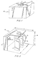
- the coaxial resonator includes a cavity such as the rectangular cavity 10. Disposed on the top of the rectangular cavity 10 is a stepper motor 11 or some other adjustment device such as an adjustment screw. Preferably, the stepper motor 11 is capable of being laterally displaced in the direction of the double arrow A-A.
- a cross sectional perspective view taken along the line 2-2 of Fig. 1 is provided.
- an RF output coil 20 Disposed within the rectangular cavity 10, there is an RF output coil 20 and an I-beam shaped element 12 orthogonally placed against the electrical field between the plates that make up the capacitor.
- the plates of the capacitor include the front wall 13 of the rectangular cavity 10 and the closing plate 16.
- the I-beam shaped element 12 has the property of introducing frequency adjustment (tuning) over a wide span when rotating the I-beam in the field. To achieve the same tuning span with prior art resonators, one would have to increase the length of the center conductor 15 in order to, for example, broaden the distance S between the capacitor plates 13, 16.
- a plan view illustrates the rectangular cavity 10 with the top wall removed.
- An RF signal is input to the rectangular cavity via a coaxial cable 21 and a RF input loop 19.
- An RF signal is output from the rectangular cavity via a coaxial cable 22 and a RF output loop 20.
- the fundamental resonator frequency f 0 of the cavity 10 is settled through the adjustment length L of a coaxial center conductor 15 and/or its closing plate 16.
- the design and/or dimensions of the closing plate 16 also affect the adjustment of the fundamental resonator frequency f 0.
- the rotation of the I-beam 12 is achieved with e.g., the stepper-motor 11, an adjustment screw or other known adjustment means which is attached to an isolated shaft 17.
- a 90° rotation of the I-beam 12 adjusts the resonance frequency between maximum and minimum i.e., between 4max and 4min on a 360° rotation.
- the relation between the height and the width of the I-beam 12 when achieving maximum Af should be preferably 0.5.
- the diagonal dimension of the I-beam 12 is settled through the formula S-2*L (where L ⁇ 10 mm) in order to accomplish maximum ⁇ f and good voltage flash-over resistance.
- the diagonal dimension is depicted in Fig. 3 by the dotted line a-b.
- the statement placed in the parenthesis is power related, meaning L ⁇ 10 mm for less power (high power being approximately 50w).
- the oval design of the closing plate or top-capacitance 16 improves the voltage isolation distance i.e, the S-measure increases. Improved Af through the oval shape of closing plate 16 is a consequence resulting from the increased projected surface of the I-beam 12.
- the present invention also makes it possible to move laterally the adjusting device 11 (see the double arrow A-A of Fig. 1 which illustrates the movement of the stepper motor), thereby causing the attached I-beam 12 to move laterally between the capacitor plates 13, 16.
- This lateral movement of the I-beam 12 facilitates the 'catch' of the correct frequency range including the location of f 0 via the so called parking frequency.
- the present invention provides a resonator, such as a ⁇ /4-resonator, with a simple frequency adjustment means 11 which includes either a manual rotating device and/or an automatically driven device, for example, one driven by the stepper motor.
Landscapes
- Control Of Motors That Do Not Use Commutators (AREA)
Applications Claiming Priority (3)
| Application Number | Priority Date | Filing Date | Title |
|---|---|---|---|
| US07/957,383 US5285178A (en) | 1992-10-07 | 1992-10-07 | Combiner resonator having an I-beam shaped element disposed within its cavity |
| US957383 | 1992-10-07 | ||
| PCT/SE1993/000769 WO1994008359A1 (en) | 1992-10-07 | 1993-09-23 | Combiner resonator having an i-beam shaped element disposed within its cavity |
Publications (2)
| Publication Number | Publication Date |
|---|---|
| EP0615657A1 EP0615657A1 (en) | 1994-09-21 |
| EP0615657B1 true EP0615657B1 (en) | 1998-10-28 |
Family
ID=25499500
Family Applications (1)
| Application Number | Title | Priority Date | Filing Date |
|---|---|---|---|
| EP93923074A Expired - Lifetime EP0615657B1 (en) | 1992-10-07 | 1993-09-23 | Resonator having an i-beam shaped element disposed within its cavity |
Country Status (16)
| Country | Link |
|---|---|
| US (1) | US5285178A (da) |
| EP (1) | EP0615657B1 (da) |
| KR (1) | KR940704072A (da) |
| CN (1) | CN1038886C (da) |
| AU (1) | AU665645B2 (da) |
| BR (1) | BR9305663A (da) |
| CA (1) | CA2125278A1 (da) |
| DE (1) | DE69321821T2 (da) |
| DK (1) | DK0615657T3 (da) |
| ES (1) | ES2124796T3 (da) |
| FI (1) | FI942662A7 (da) |
| NO (1) | NO307852B1 (da) |
| NZ (1) | NZ256916A (da) |
| RU (1) | RU2106727C1 (da) |
| SG (1) | SG50656A1 (da) |
| WO (1) | WO1994008359A1 (da) |
Families Citing this family (10)
| Publication number | Priority date | Publication date | Assignee | Title |
|---|---|---|---|---|
| US5530921A (en) * | 1995-02-09 | 1996-06-25 | Telefonaktiebolaget Lm Ericsson | Enhanced system and method for implementing a backup control channel in a cellular telecommunication network |
| US5847627A (en) * | 1996-09-18 | 1998-12-08 | Illinois Superconductor Corporation | Bandstop filter coupling tuner |
| US6018663A (en) * | 1997-01-28 | 2000-01-25 | Telefonaktiebolaget Lm Ericsson | Frequency packing for dynamic frequency allocation in a radiocommunication system |
| SE513212C2 (sv) * | 1998-07-01 | 2000-07-31 | Ericsson Telefon Ab L M | Koaxial kvartsvågs kavitetsresonator |
| SE513349C2 (sv) * | 1998-08-12 | 2000-08-28 | Allgon Ab | Kavitetsresonator |
| FI119207B (fi) * | 2003-03-18 | 2008-08-29 | Filtronic Comtek Oy | Koaksiaaliresonaattorisuodatin |
| US8324989B2 (en) * | 2006-09-20 | 2012-12-04 | Alcatel Lucent | Re-entrant resonant cavities and method of manufacturing such cavities |
| CN102122742B (zh) * | 2010-12-02 | 2013-10-09 | 宁波泰立电子科技有限公司 | 具有旋转式耦合调节结构的腔体滤波器 |
| GB201203833D0 (en) * | 2012-03-05 | 2012-04-18 | Filtronic Wireless Ltd | A tuneable filter |
| CN118476121A (zh) * | 2021-12-28 | 2024-08-09 | 瑞典爱立信有限公司 | 谐振元件、一件式谐振构件及腔体滤波器 |
Family Cites Families (13)
| Publication number | Priority date | Publication date | Assignee | Title |
|---|---|---|---|---|
| US2577511A (en) * | 1946-05-24 | 1951-12-04 | Seymour B Cohn | Tunable radio frequency filter |
| US3020499A (en) * | 1960-05-20 | 1962-02-06 | Polarad Electronics Corp | Coaxial cavity tracking means |
| US3599196A (en) * | 1968-05-31 | 1971-08-10 | Pinkerton S Inc | Plural chambered, oscillator-coaxial line resonator-detector assembly for moving object detection systems |
| US4066988A (en) * | 1976-09-07 | 1978-01-03 | Stanford Research Institute | Electromagnetic resonators having slot-located switches for tuning to different frequencies |
| JPS55100701A (en) * | 1979-01-26 | 1980-07-31 | Matsushita Electric Ind Co Ltd | Coaxial resonator |
| US4386326A (en) * | 1979-08-07 | 1983-05-31 | Matsushita Electric Industrial Co., Ltd. | Dielectric-resonator-tuned microwave solid state oscillator |
| JPS56141601A (en) * | 1980-04-04 | 1981-11-05 | Matsushita Electric Ind Co Ltd | Dielectric loading coaxial resonator |
| US4445100A (en) * | 1982-01-28 | 1984-04-24 | Electronics, Missiles & Communications, Inc. | Coupling block assembly with band-reject filter |
| US4482871A (en) * | 1982-06-28 | 1984-11-13 | Motorola Inc. | Wideband VCO including variable capacitive output coupling varactor for constant power output |
| US4521754A (en) * | 1983-08-29 | 1985-06-04 | International Telephone And Telegraph Corporation | Tuning and temperature compensation arrangement for microwave resonators |
| US4535302A (en) * | 1983-12-05 | 1985-08-13 | Raytheon Company | Microwave amplifier |
| SE465197B (sv) * | 1989-12-20 | 1991-08-05 | Ericsson Telefon Ab L M | Avstaemningsanordning foer combinerfilter innefattande en dielektrisk vaagledarresonator och en med denna samverkande avstaemningskapacitans |
| DE4026062A1 (de) * | 1990-08-17 | 1992-02-20 | Ant Nachrichtentech | Abstimmvorrichtung fuer bauelemente der hochfrequenztechnik |
-
1992
- 1992-10-07 US US07/957,383 patent/US5285178A/en not_active Expired - Lifetime
-
1993
- 1993-09-23 CA CA002125278A patent/CA2125278A1/en not_active Abandoned
- 1993-09-23 FI FI942662A patent/FI942662A7/fi unknown
- 1993-09-23 SG SG1996007866A patent/SG50656A1/en unknown
- 1993-09-23 WO PCT/SE1993/000769 patent/WO1994008359A1/en not_active Ceased
- 1993-09-23 NZ NZ256916A patent/NZ256916A/en unknown
- 1993-09-23 ES ES93923074T patent/ES2124796T3/es not_active Expired - Lifetime
- 1993-09-23 EP EP93923074A patent/EP0615657B1/en not_active Expired - Lifetime
- 1993-09-23 BR BR9305663A patent/BR9305663A/pt not_active IP Right Cessation
- 1993-09-23 KR KR1019940701914A patent/KR940704072A/ko not_active Ceased
- 1993-09-23 DE DE69321821T patent/DE69321821T2/de not_active Expired - Lifetime
- 1993-09-23 RU RU94032156A patent/RU2106727C1/ru active
- 1993-09-23 DK DK93923074T patent/DK0615657T3/da active
- 1993-09-23 AU AU52877/93A patent/AU665645B2/en not_active Ceased
- 1993-10-06 CN CN93118906A patent/CN1038886C/zh not_active Expired - Lifetime
-
1994
- 1994-06-03 NO NO942069A patent/NO307852B1/no not_active IP Right Cessation
Also Published As
| Publication number | Publication date |
|---|---|
| NZ256916A (en) | 1996-02-27 |
| WO1994008359A1 (en) | 1994-04-14 |
| DE69321821D1 (de) | 1998-12-03 |
| FI942662L (fi) | 1994-06-06 |
| AU5287793A (en) | 1994-04-26 |
| BR9305663A (pt) | 1996-11-26 |
| US5285178A (en) | 1994-02-08 |
| RU2106727C1 (ru) | 1998-03-10 |
| HK1013892A1 (en) | 1999-09-10 |
| CN1038886C (zh) | 1998-06-24 |
| FI942662A0 (fi) | 1994-06-06 |
| ES2124796T3 (es) | 1999-02-16 |
| AU665645B2 (en) | 1996-01-11 |
| NO942069D0 (no) | 1994-06-03 |
| DK0615657T3 (da) | 1999-07-05 |
| SG50656A1 (en) | 1998-07-20 |
| DE69321821T2 (de) | 1999-03-18 |
| EP0615657A1 (en) | 1994-09-21 |
| NO942069L (no) | 1994-06-03 |
| NO307852B1 (no) | 2000-06-05 |
| KR940704072A (ko) | 1994-12-12 |
| FI942662A7 (fi) | 1994-06-06 |
| CA2125278A1 (en) | 1994-04-14 |
| CN1089759A (zh) | 1994-07-20 |
Similar Documents
| Publication | Publication Date | Title |
|---|---|---|
| US7057480B2 (en) | Cross-coupled dielectric resonator circuit | |
| US7310031B2 (en) | Dielectric resonators and circuits made therefrom | |
| EP0615657B1 (en) | Resonator having an i-beam shaped element disposed within its cavity | |
| CN1717838A (zh) | 谐振器滤波器 | |
| US5321374A (en) | Transverse electromagnetic mode resonator | |
| JP2000295009A (ja) | 一般応答デュアルモード、誘電体共振器にロードされる空洞共振器フィルタ | |
| US20070090899A1 (en) | Electronically tunable dielectric resonator circuits | |
| US6784768B1 (en) | Method and apparatus for coupling energy to/from dielectric resonators | |
| US4184123A (en) | Double-tuned output circuit for high power devices using coaxial cavity resonators | |
| EP1034576A1 (en) | Multi surface coupled coaxial resonator | |
| KR20010112362A (ko) | 고주파필터 | |
| US4812791A (en) | Dielectric resonator for microwave band | |
| Ishikawa et al. | 800 MHz high-power duplexer using TM dual mode dielectric resonators | |
| Ishikawa et al. | 800 MHz high power bandpass filter using TM dual mode dielectric resonators | |
| HK1013892B (en) | Resonator having an i-beam shaped element disposed within its cavity | |
| US7796000B2 (en) | Filter coupled by conductive plates having curved surface | |
| AU728314B2 (en) | Fixed tuneable loop | |
| US20250096447A1 (en) | Resonator for filters | |
| KR20000014851A (ko) | 원통 공동형 고주파 필터 | |
| WO2005045985A1 (en) | Tunable filter with cross-coupled dielectric resonators | |
| JP2593546B2 (ja) | 誘電体共振装置 | |
| Moore et al. | Resonator and preselector in balanced strip line | |
| GB2638335A (en) | Tunable filter and/or method of use thereof | |
| JPS6029213Y2 (ja) | 半同軸共振器制御発振装置 | |
| CA2375879A1 (en) | Dielectric resonator configuration for microwave-multipole bandpass filters |
Legal Events
| Date | Code | Title | Description |
|---|---|---|---|
| PUAI | Public reference made under article 153(3) epc to a published international application that has entered the european phase |
Free format text: ORIGINAL CODE: 0009012 |
|
| 17P | Request for examination filed |
Effective date: 19940429 |
|
| AK | Designated contracting states |
Kind code of ref document: A1 Designated state(s): CH DE DK ES FR GB IT LI NL SE |
|
| 17Q | First examination report despatched |
Effective date: 19971006 |
|
| GRAG | Despatch of communication of intention to grant |
Free format text: ORIGINAL CODE: EPIDOS AGRA |
|
| GRAG | Despatch of communication of intention to grant |
Free format text: ORIGINAL CODE: EPIDOS AGRA |
|
| GRAH | Despatch of communication of intention to grant a patent |
Free format text: ORIGINAL CODE: EPIDOS IGRA |
|
| GRAH | Despatch of communication of intention to grant a patent |
Free format text: ORIGINAL CODE: EPIDOS IGRA |
|
| GRAA | (expected) grant |
Free format text: ORIGINAL CODE: 0009210 |
|
| AK | Designated contracting states |
Kind code of ref document: B1 Designated state(s): CH DE DK ES FR GB IT LI NL SE |
|
| REG | Reference to a national code |
Ref country code: CH Ref legal event code: NV Representative=s name: ISLER & PEDRAZZINI AG Ref country code: CH Ref legal event code: EP |
|
| REF | Corresponds to: |
Ref document number: 69321821 Country of ref document: DE Date of ref document: 19981203 |
|
| ET | Fr: translation filed | ||
| ITF | It: translation for a ep patent filed | ||
| REG | Reference to a national code |
Ref country code: ES Ref legal event code: FG2A Ref document number: 2124796 Country of ref document: ES Kind code of ref document: T3 |
|
| REG | Reference to a national code |
Ref country code: DK Ref legal event code: T3 |
|
| PLBE | No opposition filed within time limit |
Free format text: ORIGINAL CODE: 0009261 |
|
| STAA | Information on the status of an ep patent application or granted ep patent |
Free format text: STATUS: NO OPPOSITION FILED WITHIN TIME LIMIT |
|
| 26N | No opposition filed | ||
| PGFP | Annual fee paid to national office [announced via postgrant information from national office to epo] |
Ref country code: CH Payment date: 20000904 Year of fee payment: 8 |
|
| PG25 | Lapsed in a contracting state [announced via postgrant information from national office to epo] |
Ref country code: LI Free format text: LAPSE BECAUSE OF NON-PAYMENT OF DUE FEES Effective date: 20010930 Ref country code: CH Free format text: LAPSE BECAUSE OF NON-PAYMENT OF DUE FEES Effective date: 20010930 |
|
| REG | Reference to a national code |
Ref country code: GB Ref legal event code: IF02 |
|
| REG | Reference to a national code |
Ref country code: CH Ref legal event code: PL |
|
| PGFP | Annual fee paid to national office [announced via postgrant information from national office to epo] |
Ref country code: NL Payment date: 20020830 Year of fee payment: 10 Ref country code: FR Payment date: 20020830 Year of fee payment: 10 |
|
| PGFP | Annual fee paid to national office [announced via postgrant information from national office to epo] |
Ref country code: DK Payment date: 20020902 Year of fee payment: 10 |
|
| PGFP | Annual fee paid to national office [announced via postgrant information from national office to epo] |
Ref country code: ES Payment date: 20021009 Year of fee payment: 10 |
|
| PG25 | Lapsed in a contracting state [announced via postgrant information from national office to epo] |
Ref country code: ES Free format text: LAPSE BECAUSE OF NON-PAYMENT OF DUE FEES Effective date: 20030924 |
|
| PG25 | Lapsed in a contracting state [announced via postgrant information from national office to epo] |
Ref country code: DK Free format text: LAPSE BECAUSE OF NON-PAYMENT OF DUE FEES Effective date: 20030930 |
|
| PG25 | Lapsed in a contracting state [announced via postgrant information from national office to epo] |
Ref country code: NL Free format text: LAPSE BECAUSE OF NON-PAYMENT OF DUE FEES Effective date: 20040401 |
|
| REG | Reference to a national code |
Ref country code: DK Ref legal event code: EBP |
|
| PG25 | Lapsed in a contracting state [announced via postgrant information from national office to epo] |
Ref country code: FR Free format text: LAPSE BECAUSE OF NON-PAYMENT OF DUE FEES Effective date: 20040528 |
|
| NLV4 | Nl: lapsed or anulled due to non-payment of the annual fee |
Effective date: 20040401 |
|
| REG | Reference to a national code |
Ref country code: FR Ref legal event code: ST |
|
| REG | Reference to a national code |
Ref country code: ES Ref legal event code: FD2A Effective date: 20030924 |
|
| PG25 | Lapsed in a contracting state [announced via postgrant information from national office to epo] |
Ref country code: IT Free format text: LAPSE BECAUSE OF NON-PAYMENT OF DUE FEES Effective date: 20050923 |
|
| PGFP | Annual fee paid to national office [announced via postgrant information from national office to epo] |
Ref country code: SE Payment date: 20070926 Year of fee payment: 15 |
|
| PG25 | Lapsed in a contracting state [announced via postgrant information from national office to epo] |
Ref country code: SE Free format text: LAPSE BECAUSE OF NON-PAYMENT OF DUE FEES Effective date: 20080924 |
|
| PGFP | Annual fee paid to national office [announced via postgrant information from national office to epo] |
Ref country code: GB Payment date: 20120925 Year of fee payment: 20 |
|
| PGFP | Annual fee paid to national office [announced via postgrant information from national office to epo] |
Ref country code: DE Payment date: 20120927 Year of fee payment: 20 |
|
| REG | Reference to a national code |
Ref country code: DE Ref legal event code: R071 Ref document number: 69321821 Country of ref document: DE |
|
| REG | Reference to a national code |
Ref country code: GB Ref legal event code: PE20 Expiry date: 20130922 |
|
| PG25 | Lapsed in a contracting state [announced via postgrant information from national office to epo] |
Ref country code: DE Free format text: LAPSE BECAUSE OF EXPIRATION OF PROTECTION Effective date: 20130924 |
|
| PG25 | Lapsed in a contracting state [announced via postgrant information from national office to epo] |
Ref country code: GB Free format text: LAPSE BECAUSE OF EXPIRATION OF PROTECTION Effective date: 20130922 |