EP0614845B2 - Crane safety apparatus - Google Patents
Crane safety apparatus Download PDFInfo
- Publication number
- EP0614845B2 EP0614845B2 EP94201063A EP94201063A EP0614845B2 EP 0614845 B2 EP0614845 B2 EP 0614845B2 EP 94201063 A EP94201063 A EP 94201063A EP 94201063 A EP94201063 A EP 94201063A EP 0614845 B2 EP0614845 B2 EP 0614845B2
- Authority
- EP
- European Patent Office
- Prior art keywords
- crane
- boom
- display
- data
- screen
- Prior art date
- Legal status (The legal status is an assumption and is not a legal conclusion. Google has not performed a legal analysis and makes no representation as to the accuracy of the status listed.)
- Expired - Lifetime
Links
Images


Classifications
-
- B—PERFORMING OPERATIONS; TRANSPORTING
- B66—HOISTING; LIFTING; HAULING
- B66C—CRANES; LOAD-ENGAGING ELEMENTS OR DEVICES FOR CRANES, CAPSTANS, WINCHES, OR TACKLES
- B66C13/00—Other constructional features or details
- B66C13/18—Control systems or devices
- B66C13/46—Position indicators for suspended loads or for crane elements
-
- B—PERFORMING OPERATIONS; TRANSPORTING
- B66—HOISTING; LIFTING; HAULING
- B66C—CRANES; LOAD-ENGAGING ELEMENTS OR DEVICES FOR CRANES, CAPSTANS, WINCHES, OR TACKLES
- B66C23/00—Cranes comprising essentially a beam, boom, or triangular structure acting as a cantilever and mounted for translatory of swinging movements in vertical or horizontal planes or a combination of such movements, e.g. jib-cranes, derricks, tower cranes
- B66C23/88—Safety gear
- B66C23/90—Devices for indicating or limiting lifting moment
- B66C23/905—Devices for indicating or limiting lifting moment electrical
-
- B—PERFORMING OPERATIONS; TRANSPORTING
- B66—HOISTING; LIFTING; HAULING
- B66C—CRANES; LOAD-ENGAGING ELEMENTS OR DEVICES FOR CRANES, CAPSTANS, WINCHES, OR TACKLES
- B66C23/00—Cranes comprising essentially a beam, boom, or triangular structure acting as a cantilever and mounted for translatory of swinging movements in vertical or horizontal planes or a combination of such movements, e.g. jib-cranes, derricks, tower cranes
- B66C23/88—Safety gear
- B66C23/90—Devices for indicating or limiting lifting moment
Definitions
- the present invention relates to a crane safety apparatus, and more particularly to a crane safety apparatus having a plurality of image display modes and capable of providing an operator with crane operation status settings and safe operation in accordance with a selected image display mode.
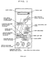
- the operation status such as crane outrigger projection, jib setting and the like is set by using switches mounted on the indication panel so that values representative of the current boom length, angle and the like are displayed from time to time.
- a safety meter is mounted on the upper portion of the indication panel. The safety meter displays in the form of bar graph the safety degree of an actual load relative to the specific load for the current crane operation status.
- Such conventional technique provides warning and automatic stop for the possible overturn, collapse, or failure of a crane.
- Japanese Patent Laid-open Publication No. 58-74496 discloses a method of regulating the operation range of a tower type crane. According to this method, a crane boom and an obstacle are schematically displayed on a screen so that it is possible to detect any contact between the boom and obstacle schematically displayed on the screen. In this case, however, for the display of an obstacle, the coordinates of the obstacle on the screen are required to be correctly set, leading to not a simple initial setting of the operation range.
- US-A-3,993,986 discloses a crane safety device for restricting the operation of cranes within a predetermined allowable operation range.
- Another problem associated with the conventional techniques is that only the safety degree of an actual load relative to the specific load, i.e., the safety degree of actual operation, is provided. As a result, an operator cannot recognize sufficiently the danger for the next possible stage and operation.
- a crane safety apparatus for use with a crane mechanism having a crane structure with a boom for lifting an article, to assist in positioning the lifted article or in preventing the crane mechanism from over turning or colliding with an obstacle comprising:
- the fundamental structure of the crane safety apparatus of this invention is shown in Fig.2A.
- the crane safety apparatus is constructed of a main unit A and a display unit B. During the operation of the apparatus, commands and data are transferred between a main unit CPU and a display unit CPU.
- the crane operation status (outrigger projection step, jib step and the like) is first required to be set. This setting is carried out at the display unit.
- An operator selects an operation status setting mode from a plurality of display modes to display a display indication (image) such as shown in Fig.3 on a display B" screen, and operates predetermined keys on a setting key group B' while monitoring the display B" screen.
- the display unit has a memory which stores therein graphics data for display images such as shown in Fig.3.
- CPU selectively reads a display image shown in Fig.3 from the memory, writes it in a video RAM, and displays the display image on the display B" screen in accordance with the data read from the video RAM.
- the display unit CPU fetches the data of outrigger step setting and the like entered from a setting key by an operator, modifies the display image so as to match the setting data, and supplies the setting data as data D B to the main unit A.
- the display unit Upon setting completion in the operation status setting mode, the display unit enters an automatic crane safety monitor mode and displays a display image such as shown in Fig.4A on the display B" screen.
- the graphics data for the display image such as shown in Fig.4A have already been stored in the memory, so CPU executes a selective read and display of the graphics data.
- the main unit A obtains from a sensor group A' the operation parameter data (such as boom length l, boom angle ⁇ , slewing angle ⁇ ) representative of the operation status of the crane mechanism which changes from time to time as the crane is operated.
- operation parameter data such as boom length l, boom angle ⁇ , slewing angle ⁇
- These operation parameters are sent directly, or after processed by CPU, to the display unit B as data A.
- the display unit B modifies from time to time the display image on the display B" screen in accordance with the data A, to thereby display the current operation status of the crane.
- the main unit A stores various data in accordance with each crane specification. Such data are typically maximum specific loads for various crane operation status. For example, a total specific load curve shown in Fig.2B is used for the operation status settings such as with outrigger intermediate projection of (5.0 m - side direction), without jib, and with boom length of 8.9 m. Such a total specific load curve is determined for each of different operation status settings and boom lengths, in accordance with each crane specification. A great number of these data are stored in ROM of the main unit A.
- the main unit A accesses ROM to obtain the maximum specific load data for the crane operation status at that time, or compares the maximum load value obtained by processing the data with the actual load and if the current crane operation status is in a danger zone, a warning is issued, or/and delivers a signal for controlling the crane mechanism A" for automatic stop of the crane operation.
- the memory of the display unit B there are stored a plurality of display image graphics data corresponding to a plurality of display modes.
- a display image such as shown in Figs.5 to 9 is selected in accordance with the display mode selected by a setting key.
- an operator can use other display modes to set the operation contents of a crane and monitor it for the effective crane operation. The operation of other display modes will be later detailed.
- the main unit A and display unit B each have a processor (CPU), and they run independently on its own program. Transmission/reception of commands and data between the main unit A and display unit B is allowed by an interrupt process.
- CPU central processing unit
- the main unit CPU 200 receives the actual load data from a stress sensor 201, and other crane operation parameter data from a slewing angle sensor 202, boom length sensor 203, boom angle sensor 204, boom top v. angle sensor 205, jib v. angle sensor 206, and stress sensor 208 respectively disposed at various positions of the crane.
- the data from the sensors 205 and 206 disposed at the top of the boom are collected to a top terminal 207 at the boom distal end, sent to a cord reel 210 at the boom distal end via an optical fiber cable 209, subjected to photoelectric conversion at the cord reel, and sent to the main unit CPU 200.
- the display unit CPU 211 is powered from the main unit CPU 200 via a line 217. Commands and data are transferred via bilateral serial lines 214 and 215 between the display unit CPU and main unit CPU 200.
- the display 212 is a matrix type dynamic drive liquid crystal display (LCD). An LCD is more preferable than other CRT, LED, plasma display and the like because the crane is generally used in outdoors and because it allows a clear display image even under strong sun light. During the night, LCD 212 is provided with back illumination.
- the setting key switch group includes a plurality of touch keys corresponding in number to a plurality of items to be set.Signals for controlling the crane mechanism are outputted to a plunger 218, magnetic valve or the like.
- the display unit CPU automatically enters the operation status setting mode, and displays the image such as shown in Fig.3.
- This mode is indicated at 301.
- Numerals generally indicated at 302 represent the boom status and they are flashing. When an operator sets desired numerals, they stop flashing and become always illuminated.
- Numeral 0 stands for the case of using only the main boom without using the jib and rooster
- numeral 1 stands for the case of using the jib with one step
- numeral 3 stands for the case of using the jib with two steps.
- numerals After completion of the boom operation status setting, numerals will flash to indicate the rightside outrigger status 303.
- Numeral 3 represents a maximum projection
- numeral 2 an intermediate projection
- numeral 1 a small projection
- numeral 0 a minimum projection
- numeral 4 no outrigger mounting
- numeral 5 a running while lifting an object.
- an operator selects a desired numeral upon activation of the ten keys on the touch panel 310A.
- the leftside outrigger status 304 is set.
- the display unit CPU causes the set numeral to change its display status from flashing to continuous illumination, and sends the set boom and outrigger status data to the main unit CPU.
- the display unit CPU After completion of the input operation for the operation status mode, the display unit CPU automatically enters the automatic crane safety monitor mode for displaying an image such as shown in Fig.4A.
- the display unit CPU displays the current crane operation status, i.e., an outrigger setting 404, slewing position 405, operation radius 406, boom angle 407, lifting load 410, lifting distance 409, and boom length 402.
- the boom length is schematically displayed in the form of bar 403 whose length changes in correspondence with the actual length of the boom.
- the safety limit of the current crane operation status is indicated at 411 in the form of bar graph.
- the numerical representation of the safety limit is indicated at 413.
- the limit (maximum) load at the current crane operation status is indicated at 408.
- the main unit CPU monitors the actual crane operation status by using the data from various sensors, accesses the memory to obtain the maximum limit load for that operation status, and checks if the accessed maximum limit load is equal to or smaller than the actual load. If the actual load becomes the maximum limit load for the current crane operation status, the main unit CPU delivers a signal for locking the crane operation mechanism.
- the display unit CPU visually provides an operator a crane operation status.
- the crane operation status reaches a limit when it has a maximum limit load, or when it has an operation range limit set by an operator (described later with reference to Fig.5). Also in the latter case, a warning is issued and the crane is automatically stopped.
- One of distinctive features of this embodiment is to display an automatic stop cause 412. If the crane stops automatically during the automatic crane safety monitor display mode, it is difficult for an operator to find at once the cause of automatic stop.
- the cause of automatic stop is difficult to be found especially for the case of crane turnover or failure caused by overload during the operation, and for the case of crane operation during the automatic crane safety monitor mode while setting the crane operation range or zone (described later with Fig.5). Further, if a predetermined length of wire continues to be released over the range of its length, then a reverse winding of the wire occurs during the crane operation. In such a case, an automatic stop is also effected.
- the cause of automatic stop is illustratively displayed at 412 on the screen.
- Fig.4B (a) to ((n) The illustrative representations of the causes of automatic stop are shown in Fig.4B (a) to ((n), the representations having the following meanings. If there are a plurality of automatic stop causes during the automatic crane safety monitor mode, the corresponding number of representations are displayed on the screen.
- the cause of automatic stop described above is displayed when certain conditions are satisfied.
- the cause of automatic stop for moment is assigned, when the actual load is equal to or larger than the limit load and the lever operation is in danger side. If the actual load is near the limit load and an operator causes to turn down or extend the boom further, or causes the winch to wind up the wire, these lever operations are in danger side.
- the main unit CPU issues a locking signal in response to these lever operations in danger side, and the display unit CPU displays the illustrative representation (a).
- the operator recognizes from the displayed automatic stop cause illustrative representation (a) that the boom cannot be turned down or extended and that the crane can be released from the danger by other operations such as lifting the boom.
- the crane enters the automatic stop, and the moment automatic stop cause representation is displayed.
- the crane automatic stop is released and the cause representation disappears.
- the crane operation lever is turned to the boom extension side, the automatic stop is effected again and the moment automatic stop cause is displayed. If the crane operation lever is turned not to the boom extension side but to the boom standing side, boom compression side or winch winding back side, then the automatic stop and cause display are not effected.
- the crane operation in danger side is different for each automatic stop cause.
- the main unit CPU has stored data representative of the direction of locking the operation lever, respectively for each crane automatic stop cause. For example, if the automatic stop is effected because of the boom high limit angle, the main unit CPU supplies to the crane mechanism a signal which locks the operation lever in the direction of lifting the boom and allows it to move in the direction of turning down the boom.
- the boom movable range is also set so as not to make the boom contact with nearby buildings and the like. It is desirous if a warning is issued or the crane is automatically stopped if the boom is moved in the direction departing from the set movable range.
- the display unit CPU enters the operation range limit display mode and displays a screen image such as shown in Fig.5.
- the operation range limit display mode is indicated at 501.
- the boom is schematically shown at B, and its distal end represented by a cross is indicated at P.
- the schematically displayed boom B follows the actual boom motion, and is controlled by the display unit CPU in accordance with the operation parameters supplied from the main unit CPU.
- an operator moves the boom to the limit point (the schematically displayed boom B also moves to the limit point).
- the non-operation range is set at the hatched area at the right of the boom distal end P.
- the operation radius R is displayed as the operation radius limit value at 507 within a rectangular frame.
- higher limit of angle (B), lower limit of angle (C), and lifting distance limit (D) may also be set.
- the characteristic point of this setting is that the boom is actually moved to the limit point and a key is depressed to set the non-operation range, instead of calculating and setting the numerical limit value without moving the boom to the limit point.
- This method of setting is advantageous in that the operation range can be determined by moving the actual boom at the field location.
- the total operation limit range covering all the limits (A) to (D) such as the radius limit and the like is shows as (E).
- the boom is allowed to move within the area not hatched.
- Other numerical values representative of the actual boom are also displayed on the screen, the values including boom angle 509, actual radius 508, boom length 506, and lifting distance 505.
- a boom slewing angle range limit is displayed.
- a boom B schematically displayed within an area 511 follows the actual boom motion.
- the boom is moved to a boom slewing angle limit point and the boom slewing angle range limit is set upon activation of a setting key on the touch panel.
- the slewing angle range limit one side of the boom may be set as indicated by (F) or both sides thereof may be set as indicated by (G).
- the outrigger setting status 512 previously set is also displayed on the boom slewing display area.
- a lifting load 503 and maximum load 504 are displayed on the screen.
- the contents set during the operation range limit display mode are transferred in the form of numerical data from the display CPU to the main unit CPU.
- the display unit CPU displays the hatched area on the right side of R . If the boom moves toward the outside of the set operation limit range, the main unit CPU detects it so that a warning is issued or the crane is automatically stopped. An operator can visually recognize the motion of the boom within the allowable operation range as shown at (E) with respect to the non-operation range. It is a significant advantage that an operator can forecast the next stage boom motion.
- the display unit CPU Upon activation of a mode selection key on the touch panel 310B, the display unit CPU enters the target display mode which displays a screen image such as shown in Fig.6.
- This target display mode is used when an operator cannot see a lifting load from the operator seat of the crane.
- Target index marks 605 and 606 indicated by solid lines in Fig.6 are used for the setting of target points.
- the side of an innermost square of the target index mark corresponds to an actual length of 15 cm, that of the next square to an actual length of 30 cm, and that of the outermost square to an actual length of 60 cm.
- the crane is operated to move an actual lifting load to a target location which is set as a first target upon activation of a key on the touch panel 310B.
- the first target is the origin of the coordinate system of the screen.
- a lifting load position 607 is displayed on the screen at the position apart from the origin by a certain distance. After setting the first target, an operator can recognize from the screen the positional relation of the lifting load with the target position without seeing the actual lifting load. It is common for a crane operation to slew the crane and transfer a lifting load from the first point to the second point. In such a case, the target index mark 605 is set at the first point, and the target index mark 606 is set at the second point.
- the index marks 605 and 606 have independent coordinate systems so that the distance between the target index marks 605 and 606 is not related to an actual distance therebetween.
- the frames indicated by a dotted line are the effective display area of the coordinate systems of the first and second points, the side of the frame corresponding to an actual length of, e.g., 100 cm.
- the position of a lifting load within this effective area is represented by mark. Even if the lifting load moves outside of this area, the mark as at 607' is displayed while moving along the dotted line so that the direction of the lifting load can be recognized by an operator. While seeing the mark on the screen relative to the target index mark, an operator can continue the transfer operation of the lifting load between the first and second points without actually seeing them.
- the numerical values of the distances of the lifting load to the first and second points are displayed at the upper area of the screen at 603 and 604.
- the outrigger setting 609 and slewed boom position 608 are displayed at the lower left area of the screen.
- Reference numeral 601 indicates the display mode
- 602 indicates the safety numerical value for the crane operation during this display mode.
- the actual position of a lifting load is calculated as lifting load position data at the main unit CPU by using the data from various sensors and the data on the crane structure, and the lifting load position data are supplied to the display unit CPU.
- the display unit CPU uses the lifting load position data at that time as the origin of the index mark 605.
- the display unit CPU displays the lifting load position 607 on the screen relative to the target index mark in accordance with a difference between the current lifting load position data and the lifting load position data at the time of setting. If the lifting load moves outside of the outermost square of the index mark, the display unit CPU displays the mark along the dotted line 613 to indicate the direction of the lifting load position. If the lifting load comes thereafter near the first or second point (i.e., comes within the outermost square of the index mark), then the position is again displayed.
- FIG.6 An example of the display image shown in Fig.6 provides two independent two-dimensional target index marks. It is also possible to display three or more index marks, or three-dimensional index marks.
- the lifting load capacity of a crane depends on the posture of the crane structure such as a front, rear, right and left position, so that the boom slewing of the crane should be paid attention.
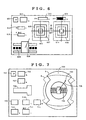
- the display unit CPU enters the limit load - slewing angle display mode upon key activation on the touch panel 310B, the display image as shown in Fig.7 appears on the screen.
- a crane is schematically shown at the center on the screen, with the outrigger setting 706 being displayed at 706.
- a boom is schematically displayed at 705 for indicating the boom slewed position.
- a cross mark 704 at the distal end of the schematically displayed boom 705 indicates the current distal end of the boom.
- a solid line A or dotted line B indicates a safety load range area 703. The operation is judged as safe so long as the cross mark 704 is displayed within the area.
- the safety load range on the screen changes with the set outrigger conditions. It is convenient for a crane operator to use this mode when the crane is slewed.
- a mode indication 701 For reference purpose, there are also displayed on the screen, a mode indication 701, safety numerical value 702, boom length numerical value, boom operation status 708, boom angle 709, actual load 710, lifting distance 711, operation radius 712, and maximum load 713.
- the typical parameter for a safety crane operation is a lifting load curve relative to the operation radius as shown in Fig.2B. It is convenient for an operator to know the operation safety margin by visually recognizing the current operation status from this safety index curve.
- the display unit CPU Upon activation of a mode switching key on the touch panel 310B, the display unit CPU enters the performance curve display mode and displays a display image on the screen as shown in Fig.8.
- the performance curve is collectively determined from a combination of crane operation parameters such as the outrigger projection state, boom length, use or non-use of jib, slewing angle and the like.
- the main unit CPU uses such operation parameters, accesses the previously stored specific load data relative to the operation radius conforming with each crane specification, and sends the specific load data to the display unit CPU.
- the display unit CPU displays an operation status performance curve 803 such as shown at the rightside on the screen.
- a + mark at 804 is displayed at the coordinate position determined by the current operation radius and actual load. An operator can know the operation margin from the position of the + mark relative to the curve.
- the numerical value of a marginal operation radius is displayed at 806 near the + mark. This numerical value indication 806 moves as the + mark 804 moves so that the operator can easily recognize this value.
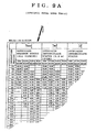
- a total specific load table such as shown in Fig.9A which is referred to for the crane safety operation.
- This table provides specific loads relative to operation radii conforming with each crane specification, when the outrigger setting status and boom length are given. While referring to the table, an operator can judge if, for example, the set outrigger and boom length are sufficient for the lifting load and operation radius of an operation to be carried out.
- the display unit CPU displays a display image as shown in Fig.9B. This mode is referred to for an operation to be carried out so that in this mode the crane is essentially in a stop state.
- An operator first uses the ten keys 310A to enter the numeral value of a desired boom length in an area 902 where a cursor flashes. During this mode, the entered boom length is not set as an actual boom length value. Thereafter, the flashing cursor moves to an area 903 wherein the numerical value of a desired slewing angle is entered.
- the outrigger status and the like have already been set during the previous operation status display mode (Fig.3).
- the display unit CPU receives from the main unit CPU (or the display unit CPU itself may have such data) maximum specific load data Wt for the operation boom angle for the given conditions, and displays them in a numerical value table 904. If the boom length and the like set for a desired operation are determined as improper upon reference to the displayed data, the table with these numerical values is reset, and a new boom length and the like are again entered.
- a mode indication 901 For reference sake, during this mode there are displayed on the screen a mode indication 901, boom operation status 907, outrigger setting 906, and slewing angle 905.
Landscapes
- Engineering & Computer Science (AREA)
- Mechanical Engineering (AREA)
- Automation & Control Theory (AREA)
- Jib Cranes (AREA)
- Control And Safety Of Cranes (AREA)
Abstract
Description
- The present invention relates to a crane safety apparatus, and more particularly to a crane safety apparatus having a plurality of image display modes and capable of providing an operator with crane operation status settings and safe operation in accordance with a selected image display mode.
- There has been proposed a crane safety apparatus (Japanese Patent Publication No.56-47117). According to the function of this crane safety apparatus, various operation parameters (boom length, boom angle, outrigger projection, jib setting, and the like) for determining the operation status of a crane are detected with sensors. A specific load for the operation status determined by these operation parameters is read from a digital memory which stores therein specific loads for various operation status, the specific load being determined in accordance with the specification of a crane. The accessed specific load is compared with the current actual load. If the actual load becomes near the specific load, a warning is issued, and if it becomes equal to the specific load, the crane operation is automatically stopped. A conventional crane safety apparatus of this type has an indication panel such as shown in Fig.1. The operation status such as crane outrigger projection, jib setting and the like is set by using switches mounted on the indication panel so that values representative of the current boom length, angle and the like are displayed from time to time. A safety meter is mounted on the upper portion of the indication panel. The safety meter displays in the form of bar graph the safety degree of an actual load relative to the specific load for the current crane operation status.
- Such conventional technique provides warning and automatic stop for the possible overturn, collapse, or failure of a crane. However, there is not provided a function to regulate the operation range of a crane when considering other buildings or the like.
- Japanese Patent Laid-open Publication No. 58-74496 discloses a method of regulating the operation range of a tower type crane. According to this method, a crane boom and an obstacle are schematically displayed on a screen so that it is possible to detect any contact between the boom and obstacle schematically displayed on the screen. In this case, however, for the display of an obstacle, the coordinates of the obstacle on the screen are required to be correctly set, leading to not a simple initial setting of the operation range.
- Further, such conventional technique does not provide a function to ensure proper and safe operation at the operation site which an operator cannot visually recognize.
- US-A-3,993,986 discloses a crane safety device for restricting the operation of cranes within a predetermined allowable operation range.
- Another problem associated with the conventional techniques is that only the safety degree of an actual load relative to the specific load, i.e., the safety degree of actual operation, is provided. As a result, an operator cannot recognize sufficiently the danger for the next possible stage and operation.
- Primarily, such conventional techniques do no provide a function to selectively display a pattern to be used for a proper crane operation suitable for particular operation contents.
- According to the present invention there is provided a crane safety apparatus for use with a crane mechanism having a crane structure with a boom for lifting an article, to assist in positioning the lifted article or in preventing the crane mechanism from over turning or colliding with an obstacle comprising:
- sensors attached to a crane mechanism for generating sensor signals indicative of the operational status of the crane mechanism such as boom length, boom angle, and slewing angle;
- a display device for displaying a crane mechanism schematic diagram; and
- a processor connected to said sensors and display device, wherein said processor, in response to the signals from said sensors, updates the crane mechanism schematic diagram as the crane mechanism is being operated, characterised in that:
- said display device includes a display memory for storing graphic data to display said crane mechanism schematic diagram and a two dimensional screen for displaying a graphic image in accordance with the graphic data stored in the display memory,
- said processor, in response to the signals from said sensors, updates the graphic data of the crane mechanism schematic diagram stored in the display memory so that the crane mechanism schematic diagram graphic image on the screen represents the crane mechanism as it is being operated,
- the apparatus further includes key means for selecting one among a plurality of display modes and generating an instruction signal, and
- the processor in response to each selected display mode generates a first graphic data of a said crane mechanism schematic diagram specific to the selected display mode and representing the crane mechanism as it is being operated and in response to the instruction signal generates a second graphic data of a work zone indication pattern specific to the selected display mode, and stores the first and second graphic data into the display memory.
-
-
- Fig. 1 shows an example of an indication panel of a conventional crane safety apparatus;
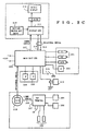
- Fig. 2A is a block diagram showing the fundamental structure of the apparatus according to this invention;
- Fig. 2B shows an example of a specific load data curve stored in the apparatus of this invention;
- Fig. 2C is a block diagram showing a particular structure of the apparatus of this invention;
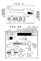
- Fig. 3 shows a display pattern on the screen during an operation status setting mode according to the apparatus of this invention;
- Fig. 4A shows a display pattern on the screen during an automatic safety monitor mode according to the apparatus of this invention;
- Fig. 4B shows illustrative representations of the causes of automatic stop to be displayed on the screen according to the apparatus of this invention;
- Fig. 5 shows a display pattern on the screen during an operation range setting mode according to the apparatus of this invention;
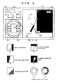
- Fig. 6 shows a display pattern on the screen during a target mode according to the apparatus of this invention;
- Fig.7 shows a display pattern on the screen during a limit load - slewing angle mode according to the apparatus of this invention;
- Fig.8 shows a display pattern on the screen during a performance curve display mode according to the apparatus of this invention;
- Fig.9A shows a part of the crane total specific load table;
- Fig.9B shows a display pattern on the screen during a performance table display mode according to the apparatus of this invention;
-
-
- The fundamental structure of the crane safety apparatus of this invention is shown in Fig.2A. The crane safety apparatus is constructed of a main unit A and a display unit B. During the operation of the apparatus, commands and data are transferred between a main unit CPU and a display unit CPU.
- Upon power-on, the crane operation status (outrigger projection step, jib step and the like) is first required to be set. This setting is carried out at the display unit. An operator selects an operation status setting mode from a plurality of display modes to display a display indication (image) such as shown in Fig.3 on a display B" screen, and operates predetermined keys on a setting key group B' while monitoring the display B" screen. The display unit has a memory which stores therein graphics data for display images such as shown in Fig.3. In accordance with a display control program in a ROM, CPU selectively reads a display image shown in Fig.3 from the memory, writes it in a video RAM, and displays the display image on the display B" screen in accordance with the data read from the video RAM. The display unit CPU fetches the data of outrigger step setting and the like entered from a setting key by an operator, modifies the display image so as to match the setting data, and supplies the setting data as data DB to the main unit A. Upon setting completion in the operation status setting mode, the display unit enters an automatic crane safety monitor mode and displays a display image such as shown in Fig.4A on the display B" screen. The graphics data for the display image such as shown in Fig.4A have already been stored in the memory, so CPU executes a selective read and display of the graphics data.
- In addition to the crane operation status setting data DB supplied from the display unit B, the main unit A obtains from a sensor group A' the operation parameter data (such as boom length ℓ, boom angle , slewing angle ) representative of the operation status of the crane mechanism which changes from time to time as the crane is operated. These operation parameters are sent directly, or after processed by CPU, to the display unit B as data A. The display unit B modifies from time to time the display image on the display B" screen in accordance with the data A, to thereby display the current operation status of the crane.
- The main unit A stores various data in accordance with each crane specification. Such data are typically maximum specific loads for various crane operation status. For example, a total specific load curve shown in Fig.2B is used for the operation status settings such as with outrigger intermediate projection of (5.0 m - side direction), without jib, and with boom length of 8.9 m. Such a total specific load curve is determined for each of different operation status settings and boom lengths, in accordance with each crane specification. A great number of these data are stored in ROM of the main unit A.
- In accordance with the crane operation status setting data DB supplied from the display unit B and the crane operation status parameters changing with time supplied from the sensor group A', the main unit A accesses ROM to obtain the maximum specific load data for the crane operation status at that time, or compares the maximum load value obtained by processing the data with the actual load and if the current crane operation status is in a danger zone, a warning is issued, or/and delivers a signal for controlling the crane mechanism A" for automatic stop of the crane operation.
- In the memory of the display unit B, there are stored a plurality of display image graphics data corresponding to a plurality of display modes. A display image such as shown in Figs.5 to 9 is selected in accordance with the display mode selected by a setting key. In addition to the automatic crane safety monitor display mode shown in Fig.4 conventionally provided in general, an operator can use other display modes to set the operation contents of a crane and monitor it for the effective crane operation. The operation of other display modes will be later detailed.
- The main unit A and display unit B each have a processor (CPU), and they run independently on its own program. Transmission/reception of commands and data between the main unit A and display unit B is allowed by an interrupt process.
- Referring to Fig.2C, the
main unit CPU 200 receives the actual load data from astress sensor 201, and other crane operation parameter data from aslewing angle sensor 202,boom length sensor 203,boom angle sensor 204, boom top v.angle sensor 205, jib v.angle sensor 206, andstress sensor 208 respectively disposed at various positions of the crane. The data from thesensors top terminal 207 at the boom distal end, sent to acord reel 210 at the boom distal end via anoptical fiber cable 209, subjected to photoelectric conversion at the cord reel, and sent to themain unit CPU 200. Thedisplay unit CPU 211 is powered from themain unit CPU 200 via aline 217. Commands and data are transferred via bilateralserial lines main unit CPU 200. Thedisplay 212 is a matrix type dynamic drive liquid crystal display (LCD). An LCD is more preferable than other CRT, LED, plasma display and the like because the crane is generally used in outdoors and because it allows a clear display image even under strong sun light. During the night,LCD 212 is provided with back illumination. The setting key switch group includes a plurality of touch keys corresponding in number to a plurality of items to be set.Signals for controlling the crane mechanism are outputted to aplunger 218, magnetic valve or the like. - Referring to Fig.3, after the power is turned on, the display unit CPU automatically enters the operation status setting mode, and displays the image such as shown in Fig.3. This mode is indicated at 301. Numerals generally indicated at 302 represent the boom status and they are flashing. When an operator sets desired numerals, they stop flashing and become always illuminated. First, in order to select a desired boom operation status, one of the ten keys on a
touch panel 310A is depressed. Numeral 0 stands for the case of using only the main boom without using the jib and rooster, numeral 1 stands for the case of using the jib with one step, numeral 3 stands for the case of using the jib with two steps. After completion of the boom operation status setting, numerals will flash to indicate therightside outrigger status 303.Numeral 3 represents a maximum projection, numeral 2 an intermediate projection, numeral 1 a small projection, numeral 0 a minimum projection, numeral 4 no outrigger mounting, and numeral 5 a running while lifting an object. Similar to the boom operation status setting, an operator selects a desired numeral upon activation of the ten keys on thetouch panel 310A. Following the rightside outrigger setting, theleftside outrigger status 304 is set. - The display unit CPU causes the set numeral to change its display status from flashing to continuous illumination, and sends the set boom and outrigger status data to the main unit CPU.
- After completion of the input operation for the operation status mode, the display unit CPU automatically enters the automatic crane safety monitor mode for displaying an image such as shown in Fig.4A. In accordance with the information supplied from the main unit CPU, the display unit CPU displays the current crane operation status, i.e., an outrigger setting 404, slewing
position 405,operation radius 406,boom angle 407, liftingload 410, liftingdistance 409, andboom length 402. The boom length is schematically displayed in the form ofbar 403 whose length changes in correspondence with the actual length of the boom. - The safety limit of the current crane operation status is indicated at 411 in the form of bar graph. The numerical representation of the safety limit is indicated at 413. The limit (maximum) load at the current crane operation status is indicated at 408. When the crane operation status becomes near the limit zone (when the
bar graph 411 extends to the yellow zone), a warning is issued. When the status reaches the limit, the crane is automatically stopped. The main unit CPU monitors the actual crane operation status by using the data from various sensors, accesses the memory to obtain the maximum limit load for that operation status, and checks if the accessed maximum limit load is equal to or smaller than the actual load. If the actual load becomes the maximum limit load for the current crane operation status, the main unit CPU delivers a signal for locking the crane operation mechanism. During the automatic crane safety monitor mode display, the display unit CPU visually provides an operator a crane operation status. The crane operation status reaches a limit when it has a maximum limit load, or when it has an operation range limit set by an operator (described later with reference to Fig.5). Also in the latter case, a warning is issued and the crane is automatically stopped. - One of distinctive features of this embodiment is to display an
automatic stop cause 412. If the crane stops automatically during the automatic crane safety monitor display mode, it is difficult for an operator to find at once the cause of automatic stop. The cause of automatic stop is difficult to be found especially for the case of crane turnover or failure caused by overload during the operation, and for the case of crane operation during the automatic crane safety monitor mode while setting the crane operation range or zone (described later with Fig.5). Further, if a predetermined length of wire continues to be released over the range of its length, then a reverse winding of the wire occurs during the crane operation. In such a case, an automatic stop is also effected. In the automatic crane safety monitor mode of this embodiment, the cause of automatic stop is illustratively displayed at 412 on the screen. - The illustrative representations of the causes of automatic stop are shown in Fig.4B (a) to ((n), the representations having the following meanings. If there are a plurality of automatic stop causes during the automatic crane safety monitor mode, the corresponding number of representations are displayed on the screen.
Illustrative Indications Causes of Automatic Stop (a) automatic stop for moment (limit load) (b) automatic stop for lower angle (c) automatic stop for higher angle (d) automatic stop for most straight standing of boom (e) automatic stop for right slewing (f) automatic stop for left slewing (g) automatic stop for spiraling (h) automatic stop for releasing (i) automatic stop for radius limit (j) automatic stop for lifting distance limit (k) automatic stop for limitation of low angle (I) automatic stop for limitation of high angle (m) automatic stop for right slewing limit (n) automatic stop for left slewing limit - The cause of automatic stop described above is displayed when certain conditions are satisfied. For example, the cause of automatic stop for moment is assigned, when the actual load is equal to or larger than the limit load and the lever operation is in danger side. If the actual load is near the limit load and an operator causes to turn down or extend the boom further, or causes the winch to wind up the wire, these lever operations are in danger side. The main unit CPU issues a locking signal in response to these lever operations in danger side, and the display unit CPU displays the illustrative representation (a). Upon the automatic stop, the operator recognizes from the displayed automatic stop cause illustrative representation (a) that the boom cannot be turned down or extended and that the crane can be released from the danger by other operations such as lifting the boom. As above, if the crane is turned down and the actual load exceeds the limit load, the crane enters the automatic stop, and the moment automatic stop cause representation is displayed. At this time, upon moving the crane operation lever back to the neutral position, the crane automatic stop is released and the cause representation disappears. In this condition, if the crane operation lever is turned to the boom extension side, the automatic stop is effected again and the moment automatic stop cause is displayed. If the crane operation lever is turned not to the boom extension side but to the boom standing side, boom compression side or winch winding back side, then the automatic stop and cause display are not effected.
- The crane operation in danger side is different for each automatic stop cause. The main unit CPU has stored data representative of the direction of locking the operation lever, respectively for each crane automatic stop cause. For example, if the automatic stop is effected because of the boom high limit angle, the main unit CPU supplies to the crane mechanism a signal which locks the operation lever in the direction of lifting the boom and allows it to move in the direction of turning down the boom.
- In the automatic safety monitor display mode having a number of automatic stop causes, an operator can visually recognize the automatic stop cause so that the crane operation is made very easy.
- In addition to setting the crane operation range for the crane turnover and failure limit, the boom movable range is also set so as not to make the boom contact with nearby buildings and the like. It is desirous if a warning is issued or the crane is automatically stopped if the boom is moved in the direction departing from the set movable range. In response to a depression of key A on the
touch panel 310B, the display unit CPU enters the operation range limit display mode and displays a screen image such as shown in Fig.5. The operation range limit display mode is indicated at 501. At the right side of the screen, the boom is schematically shown at B, and its distal end represented by a cross is indicated at P. The schematically displayed boom B follows the actual boom motion, and is controlled by the display unit CPU in accordance with the operation parameters supplied from the main unit CPU. In setting the boom operation radius limit, an operator moves the boom to the limit point (the schematically displayed boom B also moves to the limit point). Upon depression of key B on thetouch panel 310B, the non-operation range is set at the hatched area at the right of the boom distal end P. The operation radius R is displayed as the operation radius limit value at 507 within a rectangular frame. In addition to the radius limit (A) higher limit of angle (B), lower limit of angle (C), and lifting distance limit (D) may also be set. The characteristic point of this setting is that the boom is actually moved to the limit point and a key is depressed to set the non-operation range, instead of calculating and setting the numerical limit value without moving the boom to the limit point. This method of setting is advantageous in that the operation range can be determined by moving the actual boom at the field location. The total operation limit range covering all the limits (A) to (D) such as the radius limit and the like is shows as (E). The boom is allowed to move within the area not hatched. Other numerical values representative of the actual boom are also displayed on the screen, the values includingboom angle 509,actual radius 508,boom length 506, andlifting distance 505. - At the left of the screen, a boom slewing angle range limit is displayed. A boom B schematically displayed within an
area 511 follows the actual boom motion. The boom is moved to a boom slewing angle limit point and the boom slewing angle range limit is set upon activation of a setting key on the touch panel. As the slewing angle range limit, one side of the boom may be set as indicated by (F) or both sides thereof may be set as indicated by (G). Theoutrigger setting status 512 previously set is also displayed on the boom slewing display area. - For reference purpose, a lifting
load 503 andmaximum load 504 are displayed on the screen. - The contents set during the operation range limit display mode are transferred in the form of numerical data from the display CPU to the main unit CPU. Assuming that the radius limit setting key is depressed under the conditions of the boom length li and the boom anglei, the limit radius numerical data obtained is RL = sini . The display unit CPU displays the hatched area on the right side of R . If the boom moves toward the outside of the set operation limit range, the main unit CPU detects it so that a warning is issued or the crane is automatically stopped. An operator can visually recognize the motion of the boom within the allowable operation range as shown at (E) with respect to the non-operation range. It is a significant advantage that an operator can forecast the next stage boom motion.
- Upon activation of a mode selection key on the
touch panel 310B, the display unit CPU enters the target display mode which displays a screen image such as shown in Fig.6. This target display mode is used when an operator cannot see a lifting load from the operator seat of the crane. Target index marks 605 and 606 indicated by solid lines in Fig.6 are used for the setting of target points. The side of an innermost square of the target index mark corresponds to an actual length of 15 cm, that of the next square to an actual length of 30 cm, and that of the outermost square to an actual length of 60 cm. First, the crane is operated to move an actual lifting load to a target location which is set as a first target upon activation of a key on thetouch panel 310B. The first target is the origin of the coordinate system of the screen. A liftingload position 607 is displayed on the screen at the position apart from the origin by a certain distance. After setting the first target, an operator can recognize from the screen the positional relation of the lifting load with the target position without seeing the actual lifting load. It is common for a crane operation to slew the crane and transfer a lifting load from the first point to the second point. In such a case, thetarget index mark 605 is set at the first point, and thetarget index mark 606 is set at the second point. The index marks 605 and 606 have independent coordinate systems so that the distance between the target index marks 605 and 606 is not related to an actual distance therebetween. The frames indicated by a dotted line are the effective display area of the coordinate systems of the first and second points, the side of the frame corresponding to an actual length of, e.g., 100 cm. The position of a lifting load within this effective area is represented bymark. Even if the lifting load moves outside of this area, the
- The numerical values of the distances of the lifting load to the first and second points are displayed at the upper area of the screen at 603 and 604. For convenience purpose, the outrigger setting 609 and slewed
boom position 608 are displayed at the lower left area of the screen. For reference purpose, there are also displayed a lifting load 612 andmaximum load 611.Reference numeral 601 indicates the display mode, and 602 indicates the safety numerical value for the crane operation during this display mode. - The actual position of a lifting load is calculated as lifting load position data at the main unit CPU by using the data from various sensors and the data on the crane structure, and the lifting load position data are supplied to the display unit CPU. Upon activation of a touch key on the display unit to set a certain position as the origin of the
target index mark 605, the display unit CPU uses the lifting load position data at that time as the origin of theindex mark 605. The display unit CPU displays the liftingload position 607 on the screen relative to the target index mark in accordance with a difference between the current lifting load position data and the lifting load position data at the time of setting. If the lifting load moves outside of the outermost square of the index mark, the display unit CPU displays theline 613 to indicate the direction of the lifting load position. If the lifting load comes thereafter near the first or second point (i.e., comes within the outermost square of the index mark), then the position is again displayed. - An example of the display image shown in Fig.6 provides two independent two-dimensional target index marks. It is also possible to display three or more index marks, or three-dimensional index marks.
- The lifting load capacity of a crane depends on the posture of the crane structure such as a front, rear, right and left position, so that the boom slewing of the crane should be paid attention. When the display unit CPU enters the limit load - slewing angle display mode upon key activation on the
touch panel 310B, the display image as shown in Fig.7 appears on the screen. A crane is schematically shown at the center on the screen, with the outrigger setting 706 being displayed at 706. A boom is schematically displayed at 705 for indicating the boom slewed position. Across mark 704 at the distal end of the schematically displayedboom 705 indicates the current distal end of the boom. A solid line A or dotted line B indicates a safetyload range area 703. The operation is judged as safe so long as thecross mark 704 is displayed within the area. The safety load range on the screen changes with the set outrigger conditions. It is convenient for a crane operator to use this mode when the crane is slewed. - For reference purpose, there are also displayed on the screen, a
mode indication 701, safetynumerical value 702, boom length numerical value,boom operation status 708,boom angle 709,actual load 710, liftingdistance 711,operation radius 712, andmaximum load 713. - The typical parameter for a safety crane operation is a lifting load curve relative to the operation radius as shown in Fig.2B. It is convenient for an operator to know the operation safety margin by visually recognizing the current operation status from this safety index curve. Upon activation of a mode switching key on the
touch panel 310B, the display unit CPU enters the performance curve display mode and displays a display image on the screen as shown in Fig.8. The performance curve is collectively determined from a combination of crane operation parameters such as the outrigger projection state, boom length, use or non-use of jib, slewing angle and the like. The main unit CPU uses such operation parameters, accesses the previously stored specific load data relative to the operation radius conforming with each crane specification, and sends the specific load data to the display unit CPU. The display unit CPU displays an operationstatus performance curve 803 such as shown at the rightside on the screen. A + mark at 804 is displayed at the coordinate position determined by the current operation radius and actual load. An operator can know the operation margin from the position of the + mark relative to the curve. The numerical value of a marginal operation radius is displayed at 806 near the + mark. Thisnumerical value indication 806 moves as the +mark 804 moves so that the operator can easily recognize this value. - For reference purpose, during the performance curve display mode, there are displayed a current
actual load 811,boom slewing status 808, outrigger setting 809, andboom operation status 810. - There is provided a total specific load table such as shown in Fig.9A which is referred to for the crane safety operation. This table provides specific loads relative to operation radii conforming with each crane specification, when the outrigger setting status and boom length are given. While referring to the table, an operator can judge if, for example, the set outrigger and boom length are sufficient for the lifting load and operation radius of an operation to be carried out. Upon key activation on the
touch panel 310B, the display unit CPU displays a display image as shown in Fig.9B. This mode is referred to for an operation to be carried out so that in this mode the crane is essentially in a stop state. An operator first uses the tenkeys 310A to enter the numeral value of a desired boom length in anarea 902 where a cursor flashes. During this mode, the entered boom length is not set as an actual boom length value. Thereafter, the flashing cursor moves to anarea 903 wherein the numerical value of a desired slewing angle is entered. The outrigger status and the like have already been set during the previous operation status display mode (Fig.3). Upon input of these values, the display unit CPU receives from the main unit CPU (or the display unit CPU itself may have such data) maximum specific load data Wt for the operation boom angle for the given conditions, and displays them in a numerical value table 904. If the boom length and the like set for a desired operation are determined as improper upon reference to the displayed data, the table with these numerical values is reset, and a new boom length and the like are again entered. - For reference sake, during this mode there are displayed on the screen a
mode indication 901,boom operation status 907, outrigger setting 906, and slewing angle 905.
Claims (8)
- A crane safety apparatus for use with a crane mechanism having a crane structure with a boom for lifting an article, to assist in positioning the lifted article or in preventing the crane mechanism from over turning or colliding with an obstacle comprising:characterised in that:sensors (201-208) attached to a crane mechanism for generating sensor signals indicative of the operational status of the crane mechanism such as boom length, boom angle, and slewing angle;a display device (211, 212, 213, RAM) arranged to display a crane mechanism schematic diagram, said display device including a display memory storing graphic data to display said crane mechanism schematic diagram and a two dimensional screen arranged to display a graphic image in accordance with the graphic data stored in the display memory, anda processor (200) connected to said sensors and display device, wherein said processor is operable in response to the signals from said sensors to update the graphic data of the crane mechanism schematic diagram stored in the display memory so that the crane mechanism schematic diagram graphic image on the screen represents the crane mechanism as it is being operated,the apparatus further includes key means (310A, 310B) for selecting one among a plurality of display modes (FIG. 3 - FIG. 9B) corresponding to respective different crane operation modes and generating an instruction signal, andthe processor in response to each selected display mode generates a first graphic data of a said crane mechanism schematic diagram specific to the selected display mode and representing the crane mechanism as it is being operated, and in response to the instruction signal generates a second graphic data of a work zone indication pattern specific to the selected display mode, and stores the first and second graphic data into the display memory.
- A crane safety apparatus according to claim 1, wherein the processor in response to a selected operation range limit mode generates as the specific crane mechanism schematic diagram data a boom diagram (B, P) in a side view, and generates as the specific work zone indication pattern data a non-operation range (510) displayed with respect to the distal end of the currently displayed boom diagram on the screen.
- A crane safety apparatus according to claim 1, wherein the processor in response to a selected target display mode generates as the specific mechanism schematic diagram data a crane lifting position diagram (607) which varies with the change in display location in the status of the boom, and generates as the specific work zone indication pattern data a target index mark (605, 606, 613, 614) located with respect to a preselected position on the screen,
wherein said processor updates the crane lifting position diagram data in the display memory as the lifting position changes so that the crane lifting position diagram on the screen indicates the distance of the lifting position from the target. - A crane safety apparatus according to claim 3, wherein said target index mark is a two-dimensional closed area having as its center said crane lifting position diagram displayed on said screen at the time when the instruction signal occurs.
- A crane safety apparatus according to claim 4, wherein when said crane lifting position diagram moves outside of the border (613, 614) of said closed area in response to the crane mechanism operation, said crane lifting position diagram is displayed near or along said border.
- A crane safety apparatus according to claim 1 further comprising an operation limit memory for storing operation limit data and means for generating a crane outrigger status signal which indicates the crane outrigger setting status,
wherein said processor in response to a selected limit load-slewing angle display mode, generates as the specific crane mechanism schematic diagram data a boom diagram (704, 705) in which the boom is displayed in a planview as a line which rotates about the boom slewing center point on the screen and whose length varies with the boom length setting, and accesses the crane operation limit data in the operation limit memory on the basis of the crane outrigger status signal to generate as the specific work zone indication pattern data a boom safety slewing area diagram in the form of a closed curved line displaying boom safety slewing limits for safe operation of the crane mechanism about the boom slewing center point, whereby an operator can determine from the screen if the boom diagram is within the boom safety slewing area diagram to ensure safe crane operation (A, B). - A crane safety apparatus according to claim 1, wherein said processor additionally generates graphic data of an automatic stop mark (412) which indicates a cause of automatic stop.
- A crane safety apparatus according to claim 2, wherein the specific work zone indication pattern data is generated when an operator moves the boom to a limit point for the operation range.
Applications Claiming Priority (4)
| Application Number | Priority Date | Filing Date | Title |
|---|---|---|---|
| JP33019788 | 1988-12-27 | ||
| JP33019788 | 1988-12-27 | ||
| JP330197/88 | 1988-12-27 | ||
| EP89904237A EP0406419B2 (en) | 1988-12-27 | 1989-04-06 | Crane safety apparatus |
Related Parent Applications (2)
| Application Number | Title | Priority Date | Filing Date |
|---|---|---|---|
| EP89904237.8 Division | 1989-04-06 | ||
| EP89904237A Division EP0406419B2 (en) | 1988-12-27 | 1989-04-06 | Crane safety apparatus |
Publications (4)
| Publication Number | Publication Date |
|---|---|
| EP0614845A2 EP0614845A2 (en) | 1994-09-14 |
| EP0614845A3 EP0614845A3 (en) | 1994-10-26 |
| EP0614845B1 EP0614845B1 (en) | 1999-10-20 |
| EP0614845B2 true EP0614845B2 (en) | 2004-05-12 |
Family
ID=18229919
Family Applications (2)
| Application Number | Title | Priority Date | Filing Date |
|---|---|---|---|
| EP94201063A Expired - Lifetime EP0614845B2 (en) | 1988-12-27 | 1989-04-06 | Crane safety apparatus |
| EP89904237A Expired - Lifetime EP0406419B2 (en) | 1988-12-27 | 1989-04-06 | Crane safety apparatus |
Family Applications After (1)
| Application Number | Title | Priority Date | Filing Date |
|---|---|---|---|
| EP89904237A Expired - Lifetime EP0406419B2 (en) | 1988-12-27 | 1989-04-06 | Crane safety apparatus |
Country Status (7)
| Country | Link |
|---|---|
| EP (2) | EP0614845B2 (en) |
| KR (1) | KR940009268B1 (en) |
| AT (2) | ATE124381T1 (en) |
| AU (2) | AU618900B1 (en) |
| DE (2) | DE68929092T3 (en) |
| RU (1) | RU2093452C1 (en) |
| WO (1) | WO1990007465A1 (en) |
Cited By (1)
| Publication number | Priority date | Publication date | Assignee | Title |
|---|---|---|---|---|
| EP3362399B1 (en) | 2015-10-16 | 2019-08-21 | Palfinger AG | Arrangement of a control device and a mobile control module |
Families Citing this family (39)
| Publication number | Priority date | Publication date | Assignee | Title |
|---|---|---|---|---|
| JP2564060B2 (en) * | 1991-10-24 | 1996-12-18 | 株式会社神戸製鋼所 | Safety equipment for construction machinery |
| JPH07144884A (en) * | 1993-11-26 | 1995-06-06 | Komatsu Mec Corp | Mobile reach tower crane |
| FR2720438B1 (en) * | 1994-05-30 | 1996-07-05 | Camiva | Method for controlling the movement of a lifting means. |
| WO1996027548A1 (en) * | 1995-03-03 | 1996-09-12 | Komatsu Ltd. | Device for indicating movable range of mobile crane vehicle |
| DE19538264C2 (en) * | 1995-10-13 | 1999-02-18 | Pietzsch Automatisierungstech | Process and interactive control console for preparing and setting up a mobile work device |
| DE19653579B4 (en) * | 1996-12-20 | 2017-03-09 | Liebherr-Werk Biberach Gmbh | Tower Crane |
| US6140930A (en) * | 1997-02-27 | 2000-10-31 | Shaw; Jack B. | Crane safety devices and methods |
| US6744372B1 (en) | 1997-02-27 | 2004-06-01 | Jack B. Shaw | Crane safety devices and methods |
| IT1317433B1 (en) * | 2000-04-28 | 2003-07-09 | Potain Socita Anonyme | COMMAND CONTROL DEVICE FOR TOWER CRANES |
| DE10023418A1 (en) * | 2000-05-12 | 2001-11-15 | Liebherr Werk Nenzing | Procedure for overload protection of a mobile crane |
| JP4891483B2 (en) * | 2001-03-07 | 2012-03-07 | 株式会社タダノ | Working machine limit device |
| JP4709415B2 (en) * | 2001-04-17 | 2011-06-22 | 株式会社タダノ | Control device for telescopic mechanism |
| DE10155006B4 (en) * | 2001-11-06 | 2004-12-16 | Terex-Demag Gmbh & Co. Kg | Mobile crane with super lift device |
| RU2237006C2 (en) * | 2002-04-10 | 2004-09-27 | Общество с ограниченной ответственностью "Научно-производственное предприятие "Резонанс" | Load-lifting crane protection system |
| RU2246441C2 (en) * | 2002-07-31 | 2005-02-20 | Буланов Виктор Владимирович | Method of and device for automatic coordinate protection of tower crane operating in confined spaces |
| RU2251524C2 (en) * | 2002-11-18 | 2005-05-10 | Общество с ограниченной ответственностью "Научно-производственное предприятие "Резонанс" | Load-lifting crane safety system modules data exchange method and safety system of load-lifting crane |
| RU2280608C2 (en) * | 2004-11-26 | 2006-07-27 | Общество с ограниченной ответственностью "Научно-производственное предприятие "Резонанс" | Method of supporting crane operator to provide safe operation of load-lifting crane |
| RU2280610C2 (en) * | 2004-12-15 | 2006-07-27 | Общество с ограниченной ответственностью "Научно-производственное предприятие "Резонанс" | Method of setting working zone of load-lifting crane by crane operator |
| DE102005035460A1 (en) | 2005-07-28 | 2007-02-01 | Liebherr-Werk Ehingen Gmbh | Method for determining the load on cranes |
| DE102005035729A1 (en) * | 2005-07-29 | 2007-02-01 | Liebherr-Werk Ehingen Gmbh | Method for operating a crane |
| RU2305063C2 (en) * | 2005-10-31 | 2007-08-27 | Общество с ограниченной ответственностью "Научно-производственное предприятие "Резонанс" | Load-lifting crane control method |
| AT9138U1 (en) * | 2005-12-27 | 2007-05-15 | Palfinger Ag | OPERATING DEVICE FOR A LOADING CRANE |
| RU2326806C1 (en) * | 2006-08-28 | 2008-06-20 | Общество с ограниченной ответственностью "Научно-производственное предприятие "Резонанс" | Load-lifting crane safety device with graphic display (versions) |
| DE102006040782A1 (en) * | 2006-08-31 | 2008-03-20 | Liebherr-Werk Nenzing Gmbh, Nenzing | Safety and control procedures for cranes |
| RU2326046C1 (en) * | 2006-09-19 | 2008-06-10 | Общество с ограниченной ответственностью "Научно-производственное предприятие "ЭГО" | Method and system of control and anticollision protection of multiple jointly operating tower cranes |
| RU2325317C1 (en) * | 2006-10-03 | 2008-05-27 | Общество с ограниченной ответственностью "Научно-производственное предприятие "ЭГО" | Method of lifting crane control and device for its implementation |
| JP5367229B2 (en) * | 2007-03-16 | 2013-12-11 | 住友重機械工業株式会社 | Lifting magnet control system |
| RU2345944C1 (en) * | 2007-04-10 | 2009-02-10 | Общество с ограниченной ответственностью "Научно-производственное предприятие "Резонанс" | Method of improvement of safety of work of erecting crane (versions) |
| DE102008021627A1 (en) * | 2008-04-30 | 2009-11-12 | Liebherr-Werk Ehingen Gmbh | Mobile crane and method for operating a mobile crane |
| US7677401B2 (en) * | 2008-07-16 | 2010-03-16 | Manitowoc Crane Companies, Inc. | Load monitoring and control system with selective boom-up lockout |
| EP2378053B1 (en) * | 2010-04-16 | 2019-08-28 | BAUER Maschinen GmbH | Civil construction machine with computer unit for determining an adjustment range |
| EP2378054B1 (en) | 2010-04-16 | 2019-08-28 | BAUER Maschinen GmbH | Construction machine with a safety device |
| RU2448036C1 (en) * | 2010-08-04 | 2012-04-20 | Общество с ограниченной ответственностью "Научно-производственное предприятие "Резонанс" | Automotive safety device with graphical display |
| JP2013052948A (en) * | 2011-09-02 | 2013-03-21 | West Nippon Expressway Co Ltd | Safety device for vehicle for high lift work |
| JP2013052949A (en) * | 2011-09-02 | 2013-03-21 | Aichi Corp | Safety device for vehicle for high lift work |
| CN104528541B (en) * | 2014-12-15 | 2017-03-15 | 徐州重型机械有限公司 | A kind of anti-hyperextension device of single cylinder bolt-type hoist cylinder |
| DE102016104358B4 (en) | 2016-03-10 | 2019-11-07 | Manitowoc Crane Group France Sas | Method for determining the carrying capacity of a crane and crane |
| WO2020022297A1 (en) | 2018-07-25 | 2020-01-30 | 株式会社タダノ | Informing device, work vehicle, and informing method |
| DE102022113867A1 (en) | 2022-06-01 | 2023-12-07 | Liebherr-Werk Nenzing Gmbh | System for checking the functionality of a component of a mobile work machine |
Family Cites Families (8)
| Publication number | Priority date | Publication date | Assignee | Title |
|---|---|---|---|---|
| US3238521A (en) * | 1963-09-06 | 1966-03-01 | John C Minogue | Boom angle and alarm indicator |
| US4216868A (en) * | 1978-08-04 | 1980-08-12 | Eaton Corporation | Optical digital sensor for crane operating aid |
| GB2050294B (en) * | 1979-05-18 | 1983-04-07 | Coles Cranes Ltd | Safe load indicator |
| JPS60128195A (en) * | 1983-12-09 | 1985-07-09 | 株式会社小松製作所 | Display device for luff-tele-in crane |
| JPS60126491U (en) * | 1984-02-02 | 1985-08-26 | 石川島播磨重工業株式会社 | Work display boards for construction machinery, etc. |
| DE3420596C2 (en) * | 1984-06-01 | 1986-10-02 | Dr.-Ing. Ludwig Pietzsch Gmbh & Co, 7505 Ettlingen | Monitoring and control system for jib cranes |
| US4752012A (en) * | 1986-08-29 | 1988-06-21 | Harnischfeger Corporation | Crane control means employing load sensing devices |
| JP3125241B2 (en) * | 1992-10-13 | 2001-01-15 | 大有株式会社 | Drum grabber |
-
1989
- 1989-04-06 DE DE68929092T patent/DE68929092T3/en not_active Expired - Lifetime
- 1989-04-06 AT AT89904237T patent/ATE124381T1/en active
- 1989-04-06 RU SU894830987A patent/RU2093452C1/en not_active IP Right Cessation
- 1989-04-06 EP EP94201063A patent/EP0614845B2/en not_active Expired - Lifetime
- 1989-04-06 AT AT94201063T patent/ATE185772T1/en not_active IP Right Cessation
- 1989-04-06 EP EP89904237A patent/EP0406419B2/en not_active Expired - Lifetime
- 1989-04-06 DE DE68923278T patent/DE68923278T3/en not_active Expired - Lifetime
- 1989-04-06 WO PCT/JP1989/000368 patent/WO1990007465A1/en not_active Ceased
- 1989-04-06 KR KR1019900701879A patent/KR940009268B1/en not_active Expired - Fee Related
-
1990
- 1990-06-05 AU AU56299/90A patent/AU618900B1/en not_active Ceased
- 1990-06-05 AU AU56299/90D patent/AU5629990A/en active Granted
Cited By (2)
| Publication number | Priority date | Publication date | Assignee | Title |
|---|---|---|---|---|
| EP3362399B1 (en) | 2015-10-16 | 2019-08-21 | Palfinger AG | Arrangement of a control device and a mobile control module |
| EP3362399B2 (en) † | 2015-10-16 | 2024-02-14 | Palfinger AG | Arrangement of a control device and a mobile control module |
Also Published As
| Publication number | Publication date |
|---|---|
| DE68929092D1 (en) | 1999-11-25 |
| EP0406419A4 (en) | 1991-11-27 |
| DE68929092T3 (en) | 2005-01-20 |
| KR910700194A (en) | 1991-03-14 |
| ATE124381T1 (en) | 1995-07-15 |
| WO1990007465A1 (en) | 1990-07-12 |
| EP0614845A3 (en) | 1994-10-26 |
| EP0614845A2 (en) | 1994-09-14 |
| AU618900B1 (en) | 1992-01-09 |
| DE68923278D1 (en) | 1995-08-03 |
| DE68923278T3 (en) | 2004-08-05 |
| ATE185772T1 (en) | 1999-11-15 |
| DE68929092T2 (en) | 2000-06-08 |
| AU5629990A (en) | 1992-01-09 |
| EP0406419A1 (en) | 1991-01-09 |
| KR940009268B1 (en) | 1994-10-06 |
| EP0406419B1 (en) | 1995-06-28 |
| EP0406419B2 (en) | 2002-08-28 |
| EP0614845B1 (en) | 1999-10-20 |
| DE68923278T2 (en) | 1995-10-26 |
| RU2093452C1 (en) | 1997-10-20 |
Similar Documents
| Publication | Publication Date | Title |
|---|---|---|
| EP0614845B2 (en) | Crane safety apparatus | |
| US5730305A (en) | Crane safety apparatus | |
| JP7180966B2 (en) | visual outrigger monitoring system | |
| US4833615A (en) | System for the protection of an aerial device having a pivotable boom | |
| US5645181A (en) | Method for detecting a crane hook lifting distance | |
| KR19980702711A (en) | Moving range indicator of mobile crane vehicle | |
| WO1980000076A1 (en) | Crane operating aid with operator interaction | |
| CN111634820B (en) | A crane automatic warning system and method | |
| CN111761574B (en) | Method and device for judging the safety of operations that can be performed by a boom, and construction machinery | |
| EP4036046B1 (en) | Crane information display system | |
| JPH07290295A (en) | Press machine | |
| CN115052830B (en) | System and method for monitoring crane and crane with same | |
| US20240052600A1 (en) | Construction machine | |
| JPH0971387A (en) | Hoisted cargo position display device on crane truck | |
| JP2773854B2 (en) | Work display device for work vehicles | |
| JP3614498B2 (en) | Work vehicle simulation check device | |
| JPH0558589A (en) | Crane safety display | |
| JP2644352B2 (en) | Crane safety equipment | |
| JP2001039676A (en) | Display device of crane | |
| JPWO1990007465A1 (en) | Crane safety devices | |
| US20220340398A1 (en) | Crane information display system | |
| JPH07137982A (en) | Tv monitoring device for crane | |
| JP2508098Y2 (en) | Movable range display device for telescopic boom tip in mobile crane | |
| JP2800928B2 (en) | Display of fire truck with ladder | |
| JPH0811585A (en) | Apparatus for operating hydraulic control part of mobile working machine |
Legal Events
| Date | Code | Title | Description |
|---|---|---|---|
| PUAI | Public reference made under article 153(3) epc to a published international application that has entered the european phase |
Free format text: ORIGINAL CODE: 0009012 |
|
| PUAL | Search report despatched |
Free format text: ORIGINAL CODE: 0009013 |
|
| AC | Divisional application: reference to earlier application |
Ref document number: 406419 Country of ref document: EP |
|
| AK | Designated contracting states |
Kind code of ref document: A2 Designated state(s): AT BE CH DE FR GB IT LI LU NL SE |
|
| AK | Designated contracting states |
Kind code of ref document: A3 Designated state(s): AT BE CH DE FR GB IT LI LU NL SE |
|
| 17P | Request for examination filed |
Effective date: 19941129 |
|
| 17Q | First examination report despatched |
Effective date: 19970909 |
|
| GRAG | Despatch of communication of intention to grant |
Free format text: ORIGINAL CODE: EPIDOS AGRA |
|
| GRAG | Despatch of communication of intention to grant |
Free format text: ORIGINAL CODE: EPIDOS AGRA |
|
| GRAH | Despatch of communication of intention to grant a patent |
Free format text: ORIGINAL CODE: EPIDOS IGRA |
|
| GRAH | Despatch of communication of intention to grant a patent |
Free format text: ORIGINAL CODE: EPIDOS IGRA |
|
| GRAA | (expected) grant |
Free format text: ORIGINAL CODE: 0009210 |
|
| AC | Divisional application: reference to earlier application |
Ref document number: 406419 Country of ref document: EP |
|
| AK | Designated contracting states |
Kind code of ref document: B1 Designated state(s): AT BE CH DE FR GB IT LI LU NL SE |
|
| PG25 | Lapsed in a contracting state [announced via postgrant information from national office to epo] |
Ref country code: NL Free format text: LAPSE BECAUSE OF FAILURE TO SUBMIT A TRANSLATION OF THE DESCRIPTION OR TO PAY THE FEE WITHIN THE PRESCRIBED TIME-LIMIT Effective date: 19991020 Ref country code: LI Free format text: LAPSE BECAUSE OF FAILURE TO SUBMIT A TRANSLATION OF THE DESCRIPTION OR TO PAY THE FEE WITHIN THE PRESCRIBED TIME-LIMIT Effective date: 19991020 Ref country code: IT Free format text: LAPSE BECAUSE OF FAILURE TO SUBMIT A TRANSLATION OF THE DESCRIPTION OR TO PAY THE FEE WITHIN THE PRESCRIBED TIME-LIMIT;WARNING: LAPSES OF ITALIAN PATENTS WITH EFFECTIVE DATE BEFORE 2007 MAY HAVE OCCURRED AT ANY TIME BEFORE 2007. THE CORRECT EFFECTIVE DATE MAY BE DIFFERENT FROM THE ONE RECORDED. Effective date: 19991020 Ref country code: CH Free format text: LAPSE BECAUSE OF FAILURE TO SUBMIT A TRANSLATION OF THE DESCRIPTION OR TO PAY THE FEE WITHIN THE PRESCRIBED TIME-LIMIT Effective date: 19991020 Ref country code: AT Free format text: LAPSE BECAUSE OF FAILURE TO SUBMIT A TRANSLATION OF THE DESCRIPTION OR TO PAY THE FEE WITHIN THE PRESCRIBED TIME-LIMIT Effective date: 19991020 |
|
| REF | Corresponds to: |
Ref document number: 185772 Country of ref document: AT Date of ref document: 19991115 Kind code of ref document: T |
|
| REG | Reference to a national code |
Ref country code: CH Ref legal event code: EP |
|
| REF | Corresponds to: |
Ref document number: 68929092 Country of ref document: DE Date of ref document: 19991125 |
|
| ET | Fr: translation filed | ||
| NLV1 | Nl: lapsed or annulled due to failure to fulfill the requirements of art. 29p and 29m of the patents act | ||
| PG25 | Lapsed in a contracting state [announced via postgrant information from national office to epo] |
Ref country code: LU Free format text: LAPSE BECAUSE OF NON-PAYMENT OF DUE FEES Effective date: 20000406 |
|
| REG | Reference to a national code |
Ref country code: CH Ref legal event code: PL |
|
| PLBQ | Unpublished change to opponent data |
Free format text: ORIGINAL CODE: EPIDOS OPPO |
|
| PLBI | Opposition filed |
Free format text: ORIGINAL CODE: 0009260 |
|
| 26 | Opposition filed |
Opponent name: LIEBHERR-WERK EHINGEN GMBH Effective date: 20000719 |
|
| PLBF | Reply of patent proprietor to notice(s) of opposition |
Free format text: ORIGINAL CODE: EPIDOS OBSO |
|
| PLBF | Reply of patent proprietor to notice(s) of opposition |
Free format text: ORIGINAL CODE: EPIDOS OBSO |
|
| PLBF | Reply of patent proprietor to notice(s) of opposition |
Free format text: ORIGINAL CODE: EPIDOS OBSO |
|
| PLBF | Reply of patent proprietor to notice(s) of opposition |
Free format text: ORIGINAL CODE: EPIDOS OBSO |
|
| REG | Reference to a national code |
Ref country code: GB Ref legal event code: IF02 |
|
| PGFP | Annual fee paid to national office [announced via postgrant information from national office to epo] |
Ref country code: SE Payment date: 20030404 Year of fee payment: 15 |
|
| PLAW | Interlocutory decision in opposition |
Free format text: ORIGINAL CODE: EPIDOS IDOP |
|
| PGFP | Annual fee paid to national office [announced via postgrant information from national office to epo] |
Ref country code: BE Payment date: 20030619 Year of fee payment: 15 |
|
| PUAH | Patent maintained in amended form |
Free format text: ORIGINAL CODE: 0009272 |
|
| STAA | Information on the status of an ep patent application or granted ep patent |
Free format text: STATUS: PATENT MAINTAINED AS AMENDED |
|
| PG25 | Lapsed in a contracting state [announced via postgrant information from national office to epo] |
Ref country code: SE Free format text: LAPSE BECAUSE OF NON-PAYMENT OF DUE FEES Effective date: 20040407 |
|
| 27A | Patent maintained in amended form |
Effective date: 20040512 |
|
| AK | Designated contracting states |
Kind code of ref document: B2 Designated state(s): AT BE CH DE FR GB IT LI LU NL SE |
|
| ET3 | Fr: translation filed ** decision concerning opposition | ||
| PGFP | Annual fee paid to national office [announced via postgrant information from national office to epo] |
Ref country code: GB Payment date: 20070404 Year of fee payment: 19 |
|
| PGFP | Annual fee paid to national office [announced via postgrant information from national office to epo] |
Ref country code: FR Payment date: 20070411 Year of fee payment: 19 |
|
| PG25 | Lapsed in a contracting state [announced via postgrant information from national office to epo] |
Ref country code: BE Free format text: LAPSE BECAUSE OF FAILURE TO SUBMIT A TRANSLATION OF THE DESCRIPTION OR TO PAY THE FEE WITHIN THE PRESCRIBED TIME-LIMIT Effective date: 20040430 |
|
| PGFP | Annual fee paid to national office [announced via postgrant information from national office to epo] |
Ref country code: DE Payment date: 20080331 Year of fee payment: 20 |
|
| GBPC | Gb: european patent ceased through non-payment of renewal fee |
Effective date: 20080406 |
|
| REG | Reference to a national code |
Ref country code: FR Ref legal event code: ST Effective date: 20081231 |
|
| PG25 | Lapsed in a contracting state [announced via postgrant information from national office to epo] |
Ref country code: FR Free format text: LAPSE BECAUSE OF NON-PAYMENT OF DUE FEES Effective date: 20080430 |
|
| PG25 | Lapsed in a contracting state [announced via postgrant information from national office to epo] |
Ref country code: GB Free format text: LAPSE BECAUSE OF NON-PAYMENT OF DUE FEES Effective date: 20080406 |