EP2378053B1 - Civil construction machine with computer unit for determining an adjustment range - Google Patents
Civil construction machine with computer unit for determining an adjustment range Download PDFInfo
- Publication number
- EP2378053B1 EP2378053B1 EP10004084.9A EP10004084A EP2378053B1 EP 2378053 B1 EP2378053 B1 EP 2378053B1 EP 10004084 A EP10004084 A EP 10004084A EP 2378053 B1 EP2378053 B1 EP 2378053B1
- Authority
- EP
- European Patent Office
- Prior art keywords
- detecting
- unit
- construction machine
- mast
- detecting means
- Prior art date
- Legal status (The legal status is an assumption and is not a legal conclusion. Google has not performed a legal analysis and makes no representation as to the accuracy of the status listed.)
- Active
Links
Images
Classifications
-
- E—FIXED CONSTRUCTIONS
- E21—EARTH DRILLING; MINING
- E21B—EARTH DRILLING, e.g. DEEP DRILLING; OBTAINING OIL, GAS, WATER, SOLUBLE OR MELTABLE MATERIALS OR A SLURRY OF MINERALS FROM WELLS
- E21B7/00—Special methods or apparatus for drilling
- E21B7/003—Drilling with mechanical conveying means
- E21B7/005—Drilling with mechanical conveying means with helical conveying means
-
- E—FIXED CONSTRUCTIONS
- E21—EARTH DRILLING; MINING
- E21B—EARTH DRILLING, e.g. DEEP DRILLING; OBTAINING OIL, GAS, WATER, SOLUBLE OR MELTABLE MATERIALS OR A SLURRY OF MINERALS FROM WELLS
- E21B15/00—Supports for the drilling machine, e.g. derricks or masts
-
- E—FIXED CONSTRUCTIONS
- E21—EARTH DRILLING; MINING
- E21B—EARTH DRILLING, e.g. DEEP DRILLING; OBTAINING OIL, GAS, WATER, SOLUBLE OR MELTABLE MATERIALS OR A SLURRY OF MINERALS FROM WELLS
- E21B41/00—Equipment or details not covered by groups E21B15/00 - E21B40/00
- E21B41/0021—Safety devices, e.g. for preventing small objects from falling into the borehole
-
- E—FIXED CONSTRUCTIONS
- E21—EARTH DRILLING; MINING
- E21B—EARTH DRILLING, e.g. DEEP DRILLING; OBTAINING OIL, GAS, WATER, SOLUBLE OR MELTABLE MATERIALS OR A SLURRY OF MINERALS FROM WELLS
- E21B44/00—Automatic control systems specially adapted for drilling operations, i.e. self-operating systems which function to carry out or modify a drilling operation without intervention of a human operator, e.g. computer-controlled drilling systems; Systems specially adapted for monitoring a plurality of drilling variables or conditions
-
- E—FIXED CONSTRUCTIONS
- E21—EARTH DRILLING; MINING
- E21B—EARTH DRILLING, e.g. DEEP DRILLING; OBTAINING OIL, GAS, WATER, SOLUBLE OR MELTABLE MATERIALS OR A SLURRY OF MINERALS FROM WELLS
- E21B7/00—Special methods or apparatus for drilling
- E21B7/02—Drilling rigs characterized by means for land transport with their own drive, e.g. skid mounting or wheel mounting
- E21B7/022—Control of the drilling operation; Hydraulic or pneumatic means for activation or operation
Definitions
- the invention relates to a civil engineering machine according to claim 1 and to a method for operating a civil engineering machine according to claim 10.
- tilting moments can occur on the civil engineering machinery.
- Such tilting moments can be caused statically, for example by spreading loads, but also dynamically, for example by centrifugal forces.
- the US-A-4511974 discloses a forklift with a height-adjustable and tiltable lifting fork. By means of a computer unit, an adjustment range can be determined on the basis of detected status data.
- the object of the invention is to provide a civil engineering machine and a method for this, which allow a particularly safe operation with a particularly high operating reliability, in particular with regard to the tipping safety.
- the object is achieved by a civil engineering machine with the features of claim 1. Preferred embodiments are given in the dependent claims. Furthermore, the object is achieved by a method having the features of claim 10.
- a civil engineering machine is provided with a carrier unit, an actuating unit, which is adjustable relative to the carrier unit, at least one sensor for detecting state data of the civil engineering machine, and a computer unit, by which at least based on the detected state data an adjustment of the operating unit can be determined, in which the actuating unit is adjustable at a predetermined tilting security of the civil engineering machine.
- the invention is based on the recognition that when adjusting a heavy actuator unit relative to the carrier unit, which carries the actuator unit, center of gravity shifts can occur, which are associated with corresponding variable tilting moments.
- a computer unit determines an adjustment range in which the actuating unit can be moved safely relative to its carrier unit.
- the safe setting range can be distinguished, for example, by the fact that a predetermined tilting safety factor is maintained in its interior.
- corresponding characteristic fields or tables can be stored in the evaluation unit, for example.
- the determination of the adjustment range is carried out depending on the state data of the civil engineering machine, that is, the computer unit can take into account in the overall consideration that the tendency to tilt is determined not only by the projection of the actuator, but is also influenced by other factors, such as the load on the Actuator or the dynamic state of the civil engineering machine. Therefore, the state data may, for example, be data relating to the diameter of a drill pipe held by the actuation unit, which again influences the tilting moment via the associated mass of the drill pipe.
- the civil engineering machine may in particular be an earth boring device.
- the operating unit may be, for example, the drill drive for a Erdbohrtechnikmaschine, and the carrier unit of the undercarriage of the drill.
- the position of the actuating unit within the adjustment range can be determined by the computer unit, and a signal can be emitted when a limit of the adjustment range is reached.
- the actual position of the actuating unit is related to the calculated adjustment range by the computer unit, so that it can be directly assessed whether tilt-safe operation is present or whether there is a danger of tipping.
- the signal which is emitted when the limit of the adjustment range is reached it may be, for example, an operator signal, so for example, an acoustic or optical signal that can be perceived by an operator of the civil engineering machine.
- the operator is thus able to detect the approach to a dangerous area, so that the operator can take appropriate countermeasures.
- a control signal for the actuating unit can be emitted as a signal.
- the computer unit can automatically hold the actuator in the safe adjustment range, so that a particularly reliable operation is given.
- the invention can be used, in particular, in mobile civil engineering machines, since it is often necessary to pay particular attention to tipping safety. Accordingly, it is expedient that the carrier unit has a chassis.
- the carrier unit may be an undercarriage of the civil engineering machine.
- the actuating unit has at least one civil engineering tool, in particular a drilling tool.
- the actuating unit can be designed, for example, as a rotary drilling drive and / or vibrating drilling drive.
- the actuating unit relative to the support unit about a vertical axis is pivotable and radially adjustable to the vertical axis.
- Under the vertical axis can be understood in particular an at least approximately vertical axis.
- the actuating unit embodied as a drill drive is arranged on a mast which is radially adjustable relative to an uppercarriage, which in turn is pivotable relative to the carrier unit formed as an undercarriage.
- the transducer according to the invention can detect the state data by physical measurement. It may also be advantageous for at least one sensor to be provided which records status data which is entered manually by the operator. For example, it may be provided that the operator receives a selection menu of possible drill pipe diameters, for example 880 mm or 1300 mm, or the drill pipe diameter is detected automatically. According to the input, the computer unit then determines different adjustment ranges, wherein the adjustment range for larger drill pipe diameter and thus heavier drill pipe will be regularly smaller than for a smaller diameter. If a pickup is provided for detecting manually entered status data, it is advantageous that the computer unit has a memory device for storing the manually entered data. This will provide documentation to help you determine if the data entered was correct in the event of possible failure.
- a further preferred embodiment of the invention consists in that an operator-actuatable handling assistance switching device is provided, which is in signal communication with the computer unit, wherein the computer unit is adapted to modify the adjustment range as a function of a switching state of the handling assistance switching device.
- This embodiment takes into account that different operating modes frequently occur on the civil engineering machine, which require different overturning safety considerations. For example, in a drilling operation of a drill often additional forces on the drilling tool, which can increase the tendency to tilt, or it is working with angled mast, which can also increase the tendency to tilt. Therefore, a limited adjustment range can be determined in the drilling operation by the computer unit.
- the handling assistance switching device can be realized, for example, via a switch or via a touchscreen, at which the operator specifies whether a working operation, in particular drilling operation, or whether a handling operation is provided.
- the handling assistance switching device expediently has a memory device which is set up to store the choice of the operator on the handling assistance switching device.
- the extension of the adjustment range in handling mode requires that other operating parameters of the civil engineering machine and the associated overturning moments be limited.
- the extended adjustment range in the Handling mode be justified only if the winching forces of a main winch, an auxiliary winch or a feed winch are below an allowable limit.
- the handling assistance switching device may have a display which indicates to the operator the limits of these operating parameters when the handling mode is selected on the handling assistance switching device. For example, the permissible winch forces can be displayed on a display.
- a limiting unit which is set up to limit at least one operating parameter of the civil engineering machine as a function of the switching state of the handling assistance switching device.
- the critical operating parameters can be automatically limited when the handling mode is selected on the handling assistance switching device.
- the at least one operating parameter which is limited and / or displayed to the operator, may in particular be wind tensile forces. Accordingly, it may be provided that the limit purity reduces the torque of a feed winch and shuts off an auxiliary winch when handling mode is selected.
- the handling assistance switching device comprises a protective device which prevents the effect of an actuation of the handling assistance switching device when at least one operating parameter of the civil engineering machine is outside a predetermined range.
- the effect of the operation of the handling assistance switching device can be prevented if at least one operating parameter is atypical for the handling operation, and thus an extension of the adjustment range is not justified.
- the at least one operating parameter of the civil engineering machine whose limits are displayed to the operator, which is limited by means of the limiting unit and / or which is taken into account by the safety device, may in particular be a superstructure speed and / or a mast tilt.
- Inventive civil engineering machines have an upper carriage, which is arranged rotatably about a vertical axis on the carrier unit, and on which a mast is arranged, which is the actuating unit wearing. If the superstructure together with the actuating unit is rotated about the vertical axis relative to the carrier unit, then centrifugal forces can occur which increase the tendency to tilt dynamically. Therefore, a manual or automatic limitation of the superstructure speed may be advantageous.
- the mast inclination of the mast relative to the superstructure can influence the tendency to tilt, so that a limitation of the mast tilt with regard to the tipping safety can be advantageous.
- the at least one operating parameter whose limits are displayed, which is limited by means of the limiting unit and / or which is taken into account by the protective device, may also be a rotation angle of the superstructure relative to the undercarriage, since a mobile undercarriage is often not in all spatial directions equal tip over.
- the state data on the basis of which the adjustment range is determined by the computer unit, may in particular be a weight force on the actuating unit.
- the tube length can be taken into account on the actuator, because the longer the drill pipe hanging on the actuator, the greater is often the tendency to tilt.
- At least one sensor is provided for detecting a position of a mast support jib. Because the position of the mast support arm, which connects the mast with the superstructure, is a measure of the radial position of the mast and thus the position of the actuating unit relative to the superstructure, and thus determines the overturning moment.
- At least one sensor for detecting a rotational angle of the upper carriage is provided. Because the carrier unit is often not equal tilt stability in all directions. Thus, the upper carriage rotation angle of the upper carriage relative to the carrier unit, in particular about a vertical axis, also gives indications of overturning safety.
- At least one sensor is provided for detecting a tensile and / or compressive force in a feed system for a carriage.
- a carriage feed system may, in particular, be understood to mean a system which drives the operating unit relative to the mast in the vertical direction shifts. The tensile and / or compressive force acting there can likewise influence the overturning moment.
- At least one sensor is provided for detecting a tensile force in a main cable.
- a corresponding main rope may carry a drill pipe extending on the actuator unit.
- At least one sensor is provided for detecting a tensile force in an auxiliary rope.
- an auxiliary rope which can be used for example in the assembly of a drill pipe, can also cause tilting moments.
- a further embodiment is that at least one sensor is provided for detecting at least one inlet angle of the auxiliary rope, because the inlet angle can also influence the tilting moment caused by the auxiliary rope.
- the entry angle is determined in two spatial levels.
- a further preferred embodiment of the invention consists in that at least one sensor is provided for detecting at least one angle of inclination of the carrier unit.
- the inclination angle is determined in two spatial levels. The angle of inclination of the undercarriage can also influence the tilting moments.
- At least one receptacle is provided for detecting at least one inclination angle of the mast.
- the tilt angle of the mast can be understood in particular the inclination angle of the mast relative to the superstructure. This angle can also influence the tilting moments.
- the inclination angle is determined in two spatial levels.
- At least one sensor is provided for detecting a side end position of the auxiliary cable.
- the load applied to the auxiliary cable may be subject to pendulum movements, which likewise contribute to the overturning moment.
- the sensor for detecting a cable end position of the auxiliary cable can be designed in particular as a sensor for detecting the Abspulwinkels a drum for the auxiliary rope.
- At least one sensor is provided for detecting a wind speed. This takes into account that wind loads can also have a tilting moment increasing effect.
- At least one sensor is provided for detecting a rotational speed of the upper carriage.
- At least one sensor is provided for detecting a cable end position of a feed cable. Because the position of the feed rope points to the position of the actuator and thus in turn to the relevant for the tilt safety center of gravity.
- At least one sensor is provided for detecting a longitudinal position of the main cable. By detecting the end position of the main rope center of gravity coordinates can be determined, which determine the tipping moment.
- the state data is thus advantageous for the state data to be the tensile and / or pressure force in the feed system for the carriage, the tensile force in the main cable, the tensile force in the auxiliary cable, the at least one entry angle of the auxiliary cable, the at least one inclination angle of the carrier unit, the at least one inclination angle of the mast, the Seilendposition the auxiliary rope, the wind speed, the rotational speed of the upper carriage, the Seilendposition the feed rope and / or the Seilendposition of the main rope concern.
- a further preferred embodiment of the invention is that a display device is provided, with which the adjustment can be displayed together with the current position of the actuator unit, and that the display device is adapted to represent the adjustment and the current position in a common position sketch.
- the display device is set up for the adjustment range by a color Highlighting. According to this embodiment, the operator is visually displayed the safe adjustment range as well as the actual instantaneous position of the actuation unit with respect to this adjustment range. As a result, the operator is able to intuitively detect the tilting security situation.
- the invention also relates to a method for operating the civil engineering machine according to the invention, comprising a carrier unit, an actuating unit which is adjustable relative to the carrier unit, at least one sensor for detecting state data of the civil engineering machine, and a computer unit, wherein it is provided by the computer unit based on the detected state data is determined at least one adjustment range of the actuating unit, in which the actuating unit can be adjusted at a predetermined tilting safety of the civil engineering machine.
- the embodiments explained in connection with the civil engineering machine according to the invention can also be used in connection with the method according to the invention, whereby the advantages explained in connection with the civil engineering machine can be achieved.
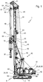
- a civil engineering machine according to the invention is in Fig. 1 shown.
- the civil engineering machine 1 is designed as a mobile Erdbohr réelle. It has a carrier unit 10 embodied as an undercarriage with a chassis 9 designed as a crawler track chassis. On this support unit 10, an upper carriage 11 of the civil engineering machine 1 is arranged. The uppercarriage 11 is provided pivotally about the vertical axis 3 on the carrier unit 10.
- mast support beams 12 are arranged, which carry a mast 14 and connect to the superstructure 11.
- the mast support beams 12 are provided pivotable about horizontally extending axes. By pivoting the mast support arm 12, the mast 14 can be radially adjusted with respect to the upper carriage 11 and thus the carrier unit 10.
- a carriage 15 is arranged vertically displaceable.
- an actuating unit 18 is provided which forms a rotary drilling drive.
- the actuating unit 18 has a driven civil engineering tool 19, 20, which is formed by a drill pipe 19 with screw drill 20 arranged on the underside.
- the drill pipe 19 may be formed in particular as a Kelly bar.
- the actuating unit 18 By pivoting the superstructure 11 relative to the carrier unit 10, the actuating unit 18 can also be pivoted relative to the carrier unit 10 about the vertical axis 3. By pivoting the mast support arm 12, the actuating unit 18 can be pivoted relative to the vertical axis 3 radially to the carrier unit 10.
- the drill pipe 19 of the civil engineering tool is suspended on a main cable 41, which extends around the head of the mast 14 around.
- a main winch 42 is provided in the rear area of the uppercarriage 11 or on the mast 14.
- an auxiliary cable 44 is guided around the mast 14, which can be actuated by means of an auxiliary cable winch 45.
- This auxiliary cable 44 can be used, for example, when the drill string 19 is mounted on the civil engineering machine 1.
- a feed system with a feed winch 48 and a running around the mast 14 feed cable 49 is provided, which is fixed to the carriage 15.
- a computer unit 23 is provided which is in signal communication with a series of receivers 51 to 64 described in more detail below. Based on the state data acquired by the sensors 51 to 64, this computer unit 23 can be used to ascertain an adjustment range of the actuating unit 18 in which the actuating unit 18 is tilt-adjustable, in particular movable radially to the vertical axis 3 and pivotable about the vertical axis 3.
- a display device 24 is provided in the operator's cab of the upper carriage 11, which is in signal communication with the computer unit 23, and with which the adjustment range can be displayed together with the actual current position of the actuator unit 18.
- the display device 24, for example have a display.
- a handling assistance switching device 30 On the display device 24 and a handling assistance switching device 30 is arranged, which can be realized for example by a touch screen. By means of this handling assistance switching device 30, the operator can enter whether a drilling operation or a handling operation is provided.
- the handling assistance switching device 30 is in signal connection with the computer unit 23, so that the computer unit 23 can vary the tilt-proof adjustment range depending on the operating mode.
- a limiter unit 32 is also provided, which is in signal communication with the computer unit 23, and which limits at least one operating parameter of the civil engineering machine 1 as a function of the switching state of the handling assistance switching device 30.
- the limiter unit 32 may limit the pivoting speed of the uppercarriage 11 about the vertical axis 3 relative to the carrier unit 10, that is to the undercarriage, when the handling mode is selected, and cancel this limitation in the drilling mode.
- the limiter unit 32 may also limit the radial position of the actuator unit 18 by limiting the deflection of the mast support beams 12.
- a protective device 33 is provided on the civil engineering machine 1, which is in signal communication with the handling assistance switching device 30 and / or with the display device 24, and which inhibits selection of the handling mode if, for example, the mast tilt is too great for this.
- the civil engineering machine 1 has a number of sensors 51 to 64, which are in signal communication with the computer unit 23, and whose data are used by the computer unit 23 to determine the adjustment range.
- a first receiver 51 for detecting a position of one of the mast support beams 12 is provided.
- the pickup 51 may be formed, for example, as a rotary encoder between the mast support boom 12 and upper carriage 11, which is arranged on the vertical pivot axis of the rear mast support boom 12.
- Another receiver 52 is provided for detecting a rotational angle of the upper carriage 11 relative to the carrier unit 10. By means of this pickup 52, the angle of rotation about the vertical axis 3 is determined by which the uppercarriage 11 is rotated relative to the carrier unit 10.
- Two further sensors 53 are provided for detecting a tensile and / or compressive force in the feed system for the carriage 15. These sensors 53 are shown in FIG Embodiment formed by two force measuring pin in the pulleys of the feed cable 49. In cylinder feeders, these transducers can be formed by pressure transducers, which measure the tensile and / or compressive force of the feed cylinder.
- Another receiver 54 is provided for detecting a tensile force in the main cable 41.
- This receiver 54 is formed by a force measuring bolt in an upper cable deflection roller of the main cable 41.
- Another receiver 55 is provided for detecting a tensile force in the auxiliary cable 44.
- This sensor 55 is formed by a force measuring bolt in an upper cable deflection roller of the auxiliary cable 44.
- the first transducer 56 determines the Seilschrägzugwinkel of the auxiliary cable 44 along the upper carriage 11 and the second transducer 57, the diagonal angle of the auxiliary cable 44 transverse to the superstructure 11. Both sensors 56, 57 are each formed by an angle sensor on the cable inlet into the upper cable guide of the auxiliary cable 44 ,
- a further sensor 58 for detecting at least one angle of inclination of the carrier unit 10 is provided on the carrier unit 10 of the civil engineering machine 1 designed as an undercarriage.
- This sensor 58 can have two inclination sensors for measuring inclination along or transversely to the carrier unit 10.
- Another receiver 59 is provided for detecting the mast slope of the mast 14.
- This sensor 59 has two sensors for an inclination angle along or transversely to the superstructure 11.
- Another receiver 60 is provided for detecting a cable end position of the auxiliary cable 44.
- This sensor 60 is designed as a rotary encoder, which is arranged on the drum of the auxiliary cable winch 45.
- the transducer 60 detects the unwound rope length.
- Another pickup 61 is provided for detecting a wind speed.
- This receiver 61 is formed by an anemometer at the top of the mast 14.
- a further sensor 62 is provided for detecting the rotational speed of the superstructure 11 relative to the carrier unit 10 about the vertical axis 3.
- This receiver 62 may in particular be arranged on the uppercarriage 11.
- a receiver 63 is provided for detecting a cable end position of the feed cable 49 of the feed system.
- this sensor 63 may be designed to measure the position of the actuating unit 18 designed as a rotary drive. From the data of the pickup 63 center of gravity coordinates of the equipment can be determined.
- another receiver 64 is provided for detecting a cable end position of the main cable 41.
- this sensor 64 may be designed to measure the position of a vortex of the main cable 41. From the cable end position of the main cable 41, taking into account the cable end position of the feed cable 49, the center of gravity coordinates of the civil engineering tool 19, 20 can be determined.
Description
Die Erfindung betrifft eine Tiefbaumaschine gemäß Anspruch 1 sowie ein Verfahren zum Betrieb einer Tiefbaumaschine gemäß Anspruch 10.The invention relates to a civil engineering machine according to
Beim Betrieb von großen Tiefbaumaschinen, wie beispielsweise Erdbohrgeräten, können an den Tiefbaumaschinen Kippmomente auftreten. Solche Kippmomente können statisch zum Beispiel durch ausladende Lasten, aber auch dynamisch zum Beispiel durch Fliehkräfte verursacht werden.When operating large civil engineering equipment, such as earth drills, tilting moments can occur on the civil engineering machinery. Such tilting moments can be caused statically, for example by spreading loads, but also dynamically, for example by centrifugal forces.
Um das Auftreten übermäßiger Kippmomente zu verhindern, ist es unter anderem bekannt, die Verstellwege ausladender Lasten konstruktiv zu begrenzen. Dies führt jedoch häufig auch zu einer Einschränkung des Betriebsbereichs der Tiefbaumaschine und somit zu einer Begrenzung der Einsatzmöglichkeiten der Tiefbaumaschine.In order to prevent the occurrence of excessive overturning moments, among other things it is known to structurally limit the displacement paths of cantilevered loads. However, this often leads to a restriction of the operating range of the civil engineering machine and thus to a limitation of the application possibilities of the civil engineering machine.
Aus der
Die
Aufgabe der Erfindung ist es, eine Tiefbaumaschine und ein Verfahren hierfür anzugeben, die bei besonders hoher Betriebszuverlässigkeit, insbesondere im Hinblick auf die Kippsicherheit einen besonders sicheren Betrieb ermöglichen. The object of the invention is to provide a civil engineering machine and a method for this, which allow a particularly safe operation with a particularly high operating reliability, in particular with regard to the tipping safety.
Die Aufgabe wird durch eine Tiefbaumaschine mit den Merkmalen des Anspruchs 1 gelöst. Bevorzugte Ausführungsbeispiele sind in den abhängigen Ansprüchen angegeben. Ferner wird die Aufgabe durch ein Verfahren mit den Merkmalen des Anspruchs 10 gelöst.The object is achieved by a civil engineering machine with the features of
Nach der Erfindung ist eine Tiefbaumaschine vorgesehen, mit einer Trägereinheit, einer Betätigungseinheit, welche gegenüber der Trägereinheit verstellbar ist, mindestens einem Aufnehmer zum Erfassen von Zustandsdaten der Tiefbaumaschine, und einer Rechnereinheit, durch welche auf Grundlage der erfassten Zustandsdaten zumindest
ein Verstellbereich der Betätigungseinheit ermittelbar ist, in welchem die Betätigungseinheit bei einer vorgegebenen Kippsicherheit der Tiefbaumaschine verstellbar ist.According to the invention, a civil engineering machine is provided with a carrier unit, an actuating unit, which is adjustable relative to the carrier unit, at least one sensor for detecting state data of the civil engineering machine, and a computer unit, by which at least based on the detected state data
an adjustment of the operating unit can be determined, in which the actuating unit is adjustable at a predetermined tilting security of the civil engineering machine.
Die Erfindung setzt an der Erkenntnis an, dass beim Verstellen einer schweren Betätigungseinheit relativ zur Trägereinheit, welche die Betätigungseinheit trägt, Schwerpunktverschiebungen auftreten können, die mit entsprechenden variablen Kippmomenten einhergehen. Um trotz dieser variablen Kippmomente einen kippsicheren Betrieb zu ermöglichen, ist erfindungsgemäß eine Rechnereinheit vorgesehen. Diese Rechnereinheit ermittelt einen Verstellbereich, in welchem die Betätigungseinheit gegenüber ihrer Trägereinheit sicher bewegt werden kann. Der sichere Stellbereich kann sich beispielsweise dadurch auszeichnen, dass in seinem Inneren ein vorgegebener Kippsicherheitsfaktor eingehalten wird. Zur Ermittlung des Verstellbereichs können in der Auswerteeinheit zum Beispiel entsprechende Kennlinienfelder oder Tabellen hinterlegt sein.The invention is based on the recognition that when adjusting a heavy actuator unit relative to the carrier unit, which carries the actuator unit, center of gravity shifts can occur, which are associated with corresponding variable tilting moments. In order to enable a tilt-safe operation despite these variable tilting moments, a computer unit is provided according to the invention. This computer unit determines an adjustment range in which the actuating unit can be moved safely relative to its carrier unit. The safe setting range can be distinguished, for example, by the fact that a predetermined tilting safety factor is maintained in its interior. For determining the adjustment range, corresponding characteristic fields or tables can be stored in the evaluation unit, for example.
Die Bestimmung des Verstellbereichs erfolgt dabei abhängig von Zustandsdaten der Tiefbaumaschine, das heißt die Rechnereinheit kann im Sinne einer Gesamtbetrachtung berücksichtigen, dass die Kippneigung nicht nur durch die Ausladung der Betätigungseinheit bestimmt wird, sondern auch durch weitere Faktoren beeinflusst wird, wie beispielsweise die Last an der Betätigungseinheit oder den dynamischen Zustand der Tiefbaumaschine. Daher kann es sich bei den Zustandsdaten beispielsweise um Daten betreffend den Durchmesser eines von der Betätigungseinheit gehaltenen Bohrrohres handeln, der über die damit einhergehende Masse des Bohrrohres wiederum das Kippmoment beeinflusst.The determination of the adjustment range is carried out depending on the state data of the civil engineering machine, that is, the computer unit can take into account in the overall consideration that the tendency to tilt is determined not only by the projection of the actuator, but is also influenced by other factors, such as the load on the Actuator or the dynamic state of the civil engineering machine. Therefore, the state data may, for example, be data relating to the diameter of a drill pipe held by the actuation unit, which again influences the tilting moment via the associated mass of the drill pipe.
Bei der Tiefbaumaschine kann es sich insbesondere um ein Erdbohrgerät handeln. In diesem Falle kann die Betätigungseinheit beispielsweise der Bohrantrieb für ein Erdbohrwerkzeug sein, und die Trägereinheit der Unterwagen des Bohrgeräts.The civil engineering machine may in particular be an earth boring device. In this case, the operating unit may be, for example, the drill drive for a Erdbohrwerkzeug, and the carrier unit of the undercarriage of the drill.
Besonders vorteilhaft ist es, dass durch die Rechnereinheit die Lage der Betätigungseinheit innerhalb des Verstellbereichs ermittelbar ist, und bei Erreichen einer Grenze des Verstellbereichs ein Signal abgebbar ist. Gemäß dieser Ausführungsform wird von der Rechnereinheit die tatsächliche Lage der Betätigungseinheit mit dem errechneten Verstellbereich in Bezug gesetzt, so dass unmittelbar beurteilt werden kann, ob ein kippsicherer Betrieb gegeben ist oder ob Kippgefahr besteht. Bei dem Signal, welches bei Erreichen der Grenze des Verstellbereichs abgegeben wird, kann es sich beispielsweise um ein Bedienersignal handeln, also beispielsweise um ein akustisches oder optisches Signal, das durch einen Bediener der Tiefbaumaschine wahrgenommen werden kann. Insbesondere kann als optisches Signal eine entsprechende Anzeige auf einem Bedienerdisplay vorgesehen sein. Der Bediener wird hierdurch in die Lage versetzt, die Annäherung an einen kippgefährlichen Bereich zu erfassen, so dass vom Bediener entsprechende Gegenmaßnahmen ergriffen werden können. Alternativ oder zusätzlich kann vorgesehen sein, dass als Signal ein Steuersignal für die Betätigungseinheit abgebbar ist. Durch Verwendung derartiger Steuersignale kann die Rechnereinheit die Betätigungseinheit automatisch im sicheren Verstellbereich halten, so dass ein besonders zuverlässiger Betrieb gegeben ist.It is particularly advantageous that the position of the actuating unit within the adjustment range can be determined by the computer unit, and a signal can be emitted when a limit of the adjustment range is reached. According to this embodiment, the actual position of the actuating unit is related to the calculated adjustment range by the computer unit, so that it can be directly assessed whether tilt-safe operation is present or whether there is a danger of tipping. In the case of the signal which is emitted when the limit of the adjustment range is reached, it may be, for example, an operator signal, so for example, an acoustic or optical signal that can be perceived by an operator of the civil engineering machine. In particular, can be provided as an optical signal, a corresponding display on an operator display. The operator is thus able to detect the approach to a dangerous area, so that the operator can take appropriate countermeasures. Alternatively or additionally, it may be provided that a control signal for the actuating unit can be emitted as a signal. By using such control signals, the computer unit can automatically hold the actuator in the safe adjustment range, so that a particularly reliable operation is given.
Die Erfindung kann insbesondere bei mobilen Tiefbaumaschinen zum Einsatz kommen, da hier oftmals der Kippsicherheit besondere Beachtung geschenkt werden muss. Demgemäß ist zweckmäßig, dass die Trägereinheit ein Fahrwerk aufweist. Insbesondere kann es sich bei der Trägereinheit um einen Unterwagen der Tiefbaumaschine handeln.The invention can be used, in particular, in mobile civil engineering machines, since it is often necessary to pay particular attention to tipping safety. Accordingly, it is expedient that the carrier unit has a chassis. In particular, the carrier unit may be an undercarriage of the civil engineering machine.
Erfindungsgemäß ist es, dass die Betätigungseinheit zumindest ein Tiefbauwerkzeug, insbesondere ein Bohrwerkzeug, aufweist. Die Betätigungseinheit kann beispielsweise als Drehbohrantrieb und/oder Rüttelbohrantrieb ausgebildet sein.According to the invention, the actuating unit has at least one civil engineering tool, in particular a drilling tool. The actuating unit can be designed, for example, as a rotary drilling drive and / or vibrating drilling drive.
Für einen besonders großen Arbeitsbereich ist es vorteilhaft, dass die Betätigungseinheit gegenüber der Trägereinheit um eine Hochachse verschwenkbar und radial zur Hochachse verstellbar ist. Unter der Hochachse kann insbesondere eine zumindest annähernd vertikal verlaufende Achse verstanden werden. Insbesondere kann vorgesehen sein, dass die als Bohrantrieb ausgebildete Betätigungseinheit an einem Mast angeordnet ist, welcher radial bezüglich einem Oberwagen verstellbar ist, der wiederum gegenüber der als Unterwagen ausgebildeten Trägereinheit verschwenkbar ist.For a particularly large work area, it is advantageous that the actuating unit relative to the support unit about a vertical axis is pivotable and radially adjustable to the vertical axis. Under the vertical axis can be understood in particular an at least approximately vertical axis. In particular, it may be provided that the actuating unit embodied as a drill drive is arranged on a mast which is radially adjustable relative to an uppercarriage, which in turn is pivotable relative to the carrier unit formed as an undercarriage.
Der erfindungsgemäße Aufnehmer kann die Zustandsdaten durch physikalische Messung erfassen. Es kann auch vorteilhaft sein, dass mindestens ein Aufnehmer vorgesehen ist, der Zustandsdaten erfasst, die vom Bediener manuell eingegeben werden. Beispielsweise kann vorgesehen sein, dass der Bediener ein Auswahlmenü von möglichen Bohrrohrdurchmessern erhält, beispielsweise 880 mm oder 1300 mm, oder der Bohrrohrdurchmesser automatisch erfasst wird. Entsprechend der Eingabe ermittelt die Rechnereinheit dann unterschiedlich große Verstellbereiche, wobei der Verstellbereich bei größerem Bohrrohrdurchmesser und somit schwererem Bohrrohr regelmäßig kleiner sein wird als bei kleinerem Durchmesser. Sofern ein Aufnehmer zum Erfassen von manuell eingegebenen Zustandsdaten vorgesehen ist, ist es vorteilhaft, dass die Rechnereinheit eine Speichereinrichtung zum Speichern der manuell eingegebenen Daten aufweist. Hierdurch wird eine Dokumentation zur Verfügung gestellt, um im Falle möglicher Störungen feststellen zu können, ob die eingegebenen Daten zutreffend waren.The transducer according to the invention can detect the state data by physical measurement. It may also be advantageous for at least one sensor to be provided which records status data which is entered manually by the operator. For example, it may be provided that the operator receives a selection menu of possible drill pipe diameters, for example 880 mm or 1300 mm, or the drill pipe diameter is detected automatically. According to the input, the computer unit then determines different adjustment ranges, wherein the adjustment range for larger drill pipe diameter and thus heavier drill pipe will be regularly smaller than for a smaller diameter. If a pickup is provided for detecting manually entered status data, it is advantageous that the computer unit has a memory device for storing the manually entered data. This will provide documentation to help you determine if the data entered was correct in the event of possible failure.
Eine weitere bevorzugte Ausführungsform der Erfindung besteht darin, dass eine von einem Bediener betätigbare Handlingsassistenzschalteinrichtung vorgesehen ist, die mit der Rechnereinheit in Signalverbindung steht, wobei die Rechnereinheit dafür eingerichtet ist, den Verstellbereich in Abhängigkeit eines Schaltzustandes der Handlingsassistenzschalteinrichtung zu modifizieren. Diese Ausführungsform berücksichtigt, dass an der Tiefbaumaschine häufig unterschiedliche Betriebsmodi auftreten, die unterschiedliche Kippsicherheitsbetrachtungen erfordern. So treten beispielsweise bei einem Bohrbetrieb eines Bohrgeräts häufig zusätzliche Kräfte am Bohrwerkzeug auf, welche die Kippneigung vergrößern können, oder es wird mit schrägem Mast gearbeitet, was ebenfalls die Kippneigung vergrößern kann. Daher kann im Bohrbetrieb von der Rechnereinheit ein eingeschränkter Verstellbereich ermittelt werden. Bei einem Handlingsbetrieb hingegen, bei dem das Werkzeug lediglich versetzt wird, beispielsweise um einen Bohreimer entfernt vom Bohrloch zu entleeren, ist zumindest ein Teil dieser zusätzlichen Belastungen häufig nicht mehr vorhanden, so dass ein erweiterter Verstellbereich vorgesehen werden kann. Die Handlingsassistenzschalteinrichtung kann beispielsweise über einen Schalter oder über einen Touchscreen realisiert werden, an denen der Bediener vorgibt, ob ein Arbeitsbetrieb, insbesondere Bohrbetrieb, oder ob ein Handlingsbetrieb vorgesehen ist. Zur Dokumentation weist die Handlingsassistenzschalteinrichtung zweckmäßigerweise eine Speichereinrichtung auf, die dafür eingerichtet ist, die Wahl des Bedieners an der Handlingsassistenzschalteinrichtung zu speichern.A further preferred embodiment of the invention consists in that an operator-actuatable handling assistance switching device is provided, which is in signal communication with the computer unit, wherein the computer unit is adapted to modify the adjustment range as a function of a switching state of the handling assistance switching device. This embodiment takes into account that different operating modes frequently occur on the civil engineering machine, which require different overturning safety considerations. For example, in a drilling operation of a drill often additional forces on the drilling tool, which can increase the tendency to tilt, or it is working with angled mast, which can also increase the tendency to tilt. Therefore, a limited adjustment range can be determined in the drilling operation by the computer unit. In contrast, in a handling operation in which the tool is merely displaced, for example, to empty a drilling bucket away from the borehole, at least part of these additional loads are often no longer present, so that an extended adjustment range can be provided. The handling assistance switching device can be realized, for example, via a switch or via a touchscreen, at which the operator specifies whether a working operation, in particular drilling operation, or whether a handling operation is provided. For documentation, the handling assistance switching device expediently has a memory device which is set up to store the choice of the operator on the handling assistance switching device.
Die Erweiterung des Verstellbereichs im Handlingsmodus setzt voraus, dass andere Betriebsparameter der Tiefbaumaschine und die damit einhergehenden Kippmomente begrenzt werden. Beispielsweise kann der erweiterte Verstellbereich im Handlingsmodus nur dann gerechtfertigt sein, wenn die Windenzugkräfte einer Hauptwinde, einer Hilfswinde oder einer Vorschubwinde unterhalb einer zulässigen Grenze liegen. Um dem Bediener die Einhaltung dieser Grenzen zu erleichtern, kann es vorteilhaft sein, wenn die Handlingsassistenzschalteinrichtung eine Anzeige aufweist, welche dem Bediener die Grenzen dieser Betriebsparameter anzeigt, wenn an der Handlingsassistenzschalteinrichtung der Handlingsmodus gewählt ist. Beispielsweise können an einem Display die zulässigen Windenzugkräfte angezeigt werden.The extension of the adjustment range in handling mode requires that other operating parameters of the civil engineering machine and the associated overturning moments be limited. For example, the extended adjustment range in the Handling mode be justified only if the winching forces of a main winch, an auxiliary winch or a feed winch are below an allowable limit. In order to make it easier for the operator to comply with these limits, it may be advantageous for the handling assistance switching device to have a display which indicates to the operator the limits of these operating parameters when the handling mode is selected on the handling assistance switching device. For example, the permissible winch forces can be displayed on a display.
Besonders vorteilhaft ist es jedoch, dass eine Begrenzereinheit vorgesehen ist, die dafür eingerichtet ist, zumindest einen Betriebsparameter der Tiefbaumaschine in Abhängigkeit des Schaltzustandes der Handlingsassistenzschalteinrichtung zu begrenzen. Gemäß dieser Ausführungsform können die kritischen Betriebsparameter automatisch begrenzt werden, wenn an der Handlingsassistenzschalteinrichtung der Handlingsmodus gewählt wird. Bei dem zumindest einen Betriebsparameter, der begrenzt und/oder dem Bediener angezeigt wird, kann es sich insbesondere um Windenzugkräfte handeln. Demgemäß kann vorgesehen sein, dass die Begrenze-r reinheit das Drehmoment einer Vorschubwinde reduziert und eine Hilfswinde abschaltet, wenn Handlingsbetrieb gewählt wird.However, it is particularly advantageous that a limiting unit is provided which is set up to limit at least one operating parameter of the civil engineering machine as a function of the switching state of the handling assistance switching device. According to this embodiment, the critical operating parameters can be automatically limited when the handling mode is selected on the handling assistance switching device. The at least one operating parameter, which is limited and / or displayed to the operator, may in particular be wind tensile forces. Accordingly, it may be provided that the limit purity reduces the torque of a feed winch and shuts off an auxiliary winch when handling mode is selected.
Weiterhin ist es vorteilhaft, dass die Handlingsassistenzschalteinrichtung eine Schutzeinrichtung umfasst, welche die Auswirkung einer Betätigung der Handlingsassistenzschalteinrichtung unterbindet, wenn zumindest ein Betriebparameter der Tiefbaumaschine außerhalb eines vorgegebenen Bereichs liegt. Gemäß dieser Ausführungsform kann die Wirkung der Betätigung der Handlingsassistenzschalteinrichtung unterbunden werden, wenn zumindest ein Betriebsparameter untypisch für den Handlingsbetrieb ist, und somit eine Erweiterung des Verstellbereichs nicht gerechtfertigt ist.Furthermore, it is advantageous that the handling assistance switching device comprises a protective device which prevents the effect of an actuation of the handling assistance switching device when at least one operating parameter of the civil engineering machine is outside a predetermined range. According to this embodiment, the effect of the operation of the handling assistance switching device can be prevented if at least one operating parameter is atypical for the handling operation, and thus an extension of the adjustment range is not justified.
Bei dem zumindest einen Betriebsparameter der Tiefbaumaschine, dessen Grenzen dem Bediener angezeigt werden, der mittels der Begrenzereinheit begrenzt wird und/oder der von der Schutzeinrichtung berücksichtigt wird, kann es sich insbesondere um eine Oberwagendrehzahl und/oder um eine Mastneigung handeln. Erfindungsgemäße Tiefbaumaschinen weisen einen Oberwagen auf, der um eine Hochachse drehbar an der Trägereinheit angeordnet ist, und an dem ein Mast angeordnet ist, der die Betätigungseinheit trägt. Wird der Oberwagen mitsamt der Betätigungseinheit relativ zur Trägereinheit um die Hochachse gedreht, so können Fliehkräfte auftreten, welche die Kipptendenz dynamisch vergrößern. Daher kann eine manuelle oder automatische Begrenzung der Oberwagendrehzahl vorteilhaft sein. Weiterhin kann auch die Mastneigung des Masts relativ zum Oberwagen die Kipptendenz beeinflussen, so dass auch eine Begrenzung der Mastneigung im Hinblick auf die Kippsicherheit vorteilhaft sein kann.The at least one operating parameter of the civil engineering machine whose limits are displayed to the operator, which is limited by means of the limiting unit and / or which is taken into account by the safety device, may in particular be a superstructure speed and / or a mast tilt. Inventive civil engineering machines have an upper carriage, which is arranged rotatably about a vertical axis on the carrier unit, and on which a mast is arranged, which is the actuating unit wearing. If the superstructure together with the actuating unit is rotated about the vertical axis relative to the carrier unit, then centrifugal forces can occur which increase the tendency to tilt dynamically. Therefore, a manual or automatic limitation of the superstructure speed may be advantageous. Furthermore, the mast inclination of the mast relative to the superstructure can influence the tendency to tilt, so that a limitation of the mast tilt with regard to the tipping safety can be advantageous.
Bei dem zumindest einen Betriebsparameter, dessen Grenzen angezeigt werden, der mittels der Begrenzereinheit begrenzt wird und/oder der von der Schutzeinrichtung berücksichtigt wird, kann es sich auch um einen Drehwinkel des Oberwagens relativ zum Unterwagen handeln, da ein fahrbarer Unterwagen häufig nicht in allen Raumrichtungen gleich kippsicher ist.The at least one operating parameter whose limits are displayed, which is limited by means of the limiting unit and / or which is taken into account by the protective device, may also be a rotation angle of the superstructure relative to the undercarriage, since a mobile undercarriage is often not in all spatial directions equal tip over.
Bei den Zustandsdaten, auf deren Grundlage der Verstellbereich von der Rechnereinheit ermittelt wird, kann es sich insbesondere um eine Gewichtskraft an der Betätigungseinheit handeln. So kann beispielsweise die Rohrlänge an der Betätigungseinheit berücksichtigt werden, denn je länger das an der Betätigungseinheit hängende Bohrrohr ist, desto größer ist häufig die Kippneigung.The state data, on the basis of which the adjustment range is determined by the computer unit, may in particular be a weight force on the actuating unit. Thus, for example, the tube length can be taken into account on the actuator, because the longer the drill pipe hanging on the actuator, the greater is often the tendency to tilt.
Erfindungsgemäß ist es, dass mindestens ein Aufnehmer zum Erfassen einer Stellung eines Maststützauslegers vorgesehen ist. Denn die Stellung des Maststützauslegers, der den Mast mit dem Oberwagen verbindet, ist ein Maß für die Radialposition des Masts und somit die Position der Betätigungseinheit relativ zum Oberwagen, und bestimmt somit das Kippmoment mit.According to the invention, at least one sensor is provided for detecting a position of a mast support jib. Because the position of the mast support arm, which connects the mast with the superstructure, is a measure of the radial position of the mast and thus the position of the actuating unit relative to the superstructure, and thus determines the overturning moment.
Ferner ist es erfindungsgemäß, dass mindestens ein Aufnehmer zum Erfassen eines Drehwinkels des Oberwagens vorgesehen ist. Denn die Trägereinheit ist häufig nicht in alle Raumrichtungen gleich kippstabil. Somit gibt der Oberwagendrehwinkel des Oberwagens relativ zur Trägereinheit, insbesondere um eine Hochachse, ebenfalls Anhaltspunkte zur Kippsicherheit.Furthermore, it is according to the invention that at least one sensor for detecting a rotational angle of the upper carriage is provided. Because the carrier unit is often not equal tilt stability in all directions. Thus, the upper carriage rotation angle of the upper carriage relative to the carrier unit, in particular about a vertical axis, also gives indications of overturning safety.
Weiterhin ist es zweckmäßig, dass mindestens ein Aufnehmer zum Erfassen einer Zug- und/oder Druckkraft in einem Vorschubsystem für einen Schlitten vorgesehen ist. Unter einem Schlittenvorschubsystem kann insbesondere ein System verstanden werden, welches die Betätigungseinheit relativ zum Mast in vertikaler Richtung verschiebt. Die dort wirkende Zug und/oder Druckkraft kann ebenfalls das Kippmoment beeinflussen.Furthermore, it is expedient that at least one sensor is provided for detecting a tensile and / or compressive force in a feed system for a carriage. A carriage feed system may, in particular, be understood to mean a system which drives the operating unit relative to the mast in the vertical direction shifts. The tensile and / or compressive force acting there can likewise influence the overturning moment.
Ferner ist es vorteilhaft, dass mindestens ein Aufnehmer zum Erfassen einer Zugkraft in einem Hauptseil vorgesehen ist. Ein entsprechendes Hauptseil kann ein Bohrgestänge tragen, das an der Betätigungseinheit verläuft. Somit kann die Hauptseilzugkraft ebenfalls das Kippmoment mitbestimmen.Furthermore, it is advantageous that at least one sensor is provided for detecting a tensile force in a main cable. A corresponding main rope may carry a drill pipe extending on the actuator unit. Thus, the Hauptseilzugkraft can also determine the overturning moment.
Darüber hinaus ist es zweckmäßig, dass mindestens ein Aufnehmer zum Erfassen einer Zugkraft in einem Hilfsseil vorgesehen ist. Denn ein solches Hilfsseil, das beispielsweise bei der Montage eines Bohrgestänges zum Einsatz kommen kann, kann ebenfalls Kippmomente verursachen.In addition, it is expedient that at least one sensor is provided for detecting a tensile force in an auxiliary rope. For such an auxiliary rope, which can be used for example in the assembly of a drill pipe, can also cause tilting moments.
Eine weitere Ausgestaltung liegt darin, dass mindestens ein Aufnehmer zum Erfassen zumindest eines Einlaufwinkels des Hilfsseils vorgesehen ist, denn der Einlaufwinkel kann ebenfalls das vom Hilfsseil verursachte Kippmoment beeinflussen. Zweckmäßigerweise wird der Einlaufwinkel in zwei Raumebenen bestimmt.A further embodiment is that at least one sensor is provided for detecting at least one inlet angle of the auxiliary rope, because the inlet angle can also influence the tilting moment caused by the auxiliary rope. Conveniently, the entry angle is determined in two spatial levels.
Eine weitere bevorzugte Ausführungsform der Erfindung besteht darin, dass mindestens ein Aufnehmer zum Erfassen zumindest eines Neigungswinkels der Trägereinheit vorgesehen ist. Zweckmäßigerweise wird der Neigungswinkel in zwei Raumebenen bestimmt. Auch der Neigungswinkel des Unterwagens kann die Kippmomente beeinflussen.A further preferred embodiment of the invention consists in that at least one sensor is provided for detecting at least one angle of inclination of the carrier unit. Conveniently, the inclination angle is determined in two spatial levels. The angle of inclination of the undercarriage can also influence the tilting moments.
Überdies ist es bevorzugt, dass mindestens ein Aufnehmer zum Erfassen zumindest eines Neigwinkels des Masts vorgesehen ist. Unter dem Neigwinkels des Masts kann insbesondere der Neigungswinkel des Masts relativ zum Oberwagen verstanden werden. Auch dieser Winkel kann die Kippmomente beeinflussen. Zweckmäßigerweise wird der Neigungswinkel in zwei Raumebenen bestimmt.Moreover, it is preferred that at least one receptacle is provided for detecting at least one inclination angle of the mast. Under the tilt angle of the mast can be understood in particular the inclination angle of the mast relative to the superstructure. This angle can also influence the tilting moments. Conveniently, the inclination angle is determined in two spatial levels.
Ferner ist es vorteilhaft, dass mindestens ein Aufnehmer zum Erfassen einer Sei -lendposition des Hilfsseils vorgesehen ist. Hierdurch kann berücksichtigt werden, dass die am Hilfsseil angeschlagene Last unter Umständen Pendelbewegungen unterliegen kann, die ebenfalls zum Kippmoment beitragen. Der Aufnehmer zum Erfassen einer Seilendposition des Hilfsseils kann insbesondere als Aufnehmer zum Erfassen des Abspulwinkels einer Trommel für das Hilfsseil ausgebildet sein.Furthermore, it is advantageous that at least one sensor is provided for detecting a side end position of the auxiliary cable. As a result, it can be considered that under certain circumstances, the load applied to the auxiliary cable may be subject to pendulum movements, which likewise contribute to the overturning moment. The sensor for detecting a cable end position of the auxiliary cable can be designed in particular as a sensor for detecting the Abspulwinkels a drum for the auxiliary rope.
Überdies ist es zweckmäßig, dass mindestens ein Aufnehmer zum Erfassen einer Windgeschwindigkeit vorgesehen ist. Hierdurch wird berücksichtigt, dass Windlasten ebenfalls kippmomentsteigernd wirken können.Moreover, it is expedient that at least one sensor is provided for detecting a wind speed. This takes into account that wind loads can also have a tilting moment increasing effect.
Ferner kann es erfindungsgemäß sein, dass mindestens ein Aufnehmer zum Erfassen einer Drehgeschwindigkeit des Oberwagens vorgesehen ist. Mit einer Drehung des Oberwagens relativ zum Trägergerät um die Hochachse gehen entsprechende Zentrifugalkräfte einher, die ebenfalls kippmomenterhöhend wirken können. Vor diesem Hintergrund ist die Drehgeschwindigkeitserfassung des Oberwagens relativ zum Trägergerät zweckmäßig.Furthermore, it can be inventively that at least one sensor is provided for detecting a rotational speed of the upper carriage. With a rotation of the superstructure relative to the carrier device about the vertical axis corresponding centrifugal forces are accompanied, which can also act tilting moment increasing. Against this background, the rotation speed detection of the superstructure relative to the carrier device is appropriate.
Darüber hinaus ist es vorteilhaft, dass mindestens ein Aufnehmer zum Erfassen einer Seilendposition eines Vorschubseils vorgesehen ist. Denn die Position des Vorschubseils weist auf die Position der Betätigungseinrichtung und somit wiederum auf die für die Kippsicherheit relevante Schwerpunktlage hin.Moreover, it is advantageous that at least one sensor is provided for detecting a cable end position of a feed cable. Because the position of the feed rope points to the position of the actuator and thus in turn to the relevant for the tilt safety center of gravity.
Weiterhin ist es bevorzugt, dass mindestens ein Aufnehmer zum Erfassen einer Sei -lendposition des Hauptseils vorgesehen ist. Durch Erfassung der Endposition des Hauptseils können Schwerpunktkoordinaten bestimmt werden, welche das Kippmoment bestimmen.Furthermore, it is preferred that at least one sensor is provided for detecting a longitudinal position of the main cable. By detecting the end position of the main rope center of gravity coordinates can be determined, which determine the tipping moment.
Demgemäß ist es also vorteilhaft, dass die Zustandsdaten die Zug- und/oder Drucckraft im Vorschubsystem für den Schlitten, die Zugkraft im Hauptseil, die Zugkraft im Hilfsseil, der zumindest eine Einlaufwinkel des Hilfsseils, der zumindest eine Neigungswinkel der Trägereinheit, der zumindest eine Neigungswinkel des Masts, die Seilendposition des Hilfsseils, die Windgeschwindigkeit, die Drehgeschwindigkeit des Oberwagens, die Seilendposition des Vorschubseils und/oder die Seilendposition des Hauptseils betreffen.Accordingly, it is thus advantageous for the state data to be the tensile and / or pressure force in the feed system for the carriage, the tensile force in the main cable, the tensile force in the auxiliary cable, the at least one entry angle of the auxiliary cable, the at least one inclination angle of the carrier unit, the at least one inclination angle of the mast, the Seilendposition the auxiliary rope, the wind speed, the rotational speed of the upper carriage, the Seilendposition the feed rope and / or the Seilendposition of the main rope concern.
Eine weitere bevorzugte Ausgestaltung der Erfindung liegt darin, dass eine Anzeigeeinrichtung vorgesehen ist, mit welcher der Verstellbereich gemeinsam mit der momentanen Lage der Betätigungseinheit anzeigbar ist, und dass die Anzeigeeinrichtung dafür eingerichtet ist, den Verstellbereich sowie die momentane Lage in einer gemeinsamen Lageskizze darzustellen. Insbesondere kann vorgesehen sein, dass die Anzeigeeinrichtung dafür eingerichtet ist, den Verstellbereich durch eine farbliche Hervorhebung darzustellen. Gemäß dieser Ausführungsform werden dem Bediener der sichere Verstellbereich sowie die tatsächliche momentane Lage der Betätigungseinheit in Bezug auf diesen Verstellbereich visuell angezeigt. Hierdurch wird dem Bediener die Kippsicherheitssituation intuitiv erfassbar dargestellt.A further preferred embodiment of the invention is that a display device is provided, with which the adjustment can be displayed together with the current position of the actuator unit, and that the display device is adapted to represent the adjustment and the current position in a common position sketch. In particular, it can be provided that the display device is set up for the adjustment range by a color Highlighting. According to this embodiment, the operator is visually displayed the safe adjustment range as well as the actual instantaneous position of the actuation unit with respect to this adjustment range. As a result, the operator is able to intuitively detect the tilting security situation.
Die Erfindung betrifft auch ein Verfahren zum Betrieb der erfindungsgemäßen Tiefbaumaschine, mit einer Trägereinheit, einer Betätigungseinheit, welche gegenüber der Trägereinheit verstellbar ist, mindestens einem Aufnehmer zum Erfassen von Zustandsdaten der Tiefbaumaschine, und einer Rechnereinheit, wobei vorgesehen ist, dass durch die Rechnereinheit auf Grundlage der erfassten Zustandsdaten zumindest ein Verstellbereich der Betätigungseinheit ermittelt wird, in welchem die Betätigungseinheit bei einer vorgegebenen Kippsicherheit der Tiefbaumaschine verstellt werden kann. Die im Zusammenhang mit der erfindungsgemäßen Tiefbaumaschine erläuterten Ausführungsbeispiele können auch im Zusammenhang mit dem erfindungsgemäßen Verfahren zum Einsatz kommen, wodurch die im Zusammenhang mit der Tiefbaumaschine erläuterten Vorteile erzielt werden können.The invention also relates to a method for operating the civil engineering machine according to the invention, comprising a carrier unit, an actuating unit which is adjustable relative to the carrier unit, at least one sensor for detecting state data of the civil engineering machine, and a computer unit, wherein it is provided by the computer unit based on the detected state data is determined at least one adjustment range of the actuating unit, in which the actuating unit can be adjusted at a predetermined tilting safety of the civil engineering machine. The embodiments explained in connection with the civil engineering machine according to the invention can also be used in connection with the method according to the invention, whereby the advantages explained in connection with the civil engineering machine can be achieved.
Die Erfindung wird nachfolgend anhand bevorzugter Ausführungsbeispiele näher erläutert, welche schematisch in der beigefügten Figur dargestellt sind. In der beigefügten Figur zeigt:
- Fig. 1
- eine Seitenansicht einer erfindungsgemäßen Tiefbaumaschine.
- Fig. 1
- a side view of a civil engineering machine according to the invention.
Eine erfindungsgemäße Tiefbaumaschine ist in
Am Oberwagen 11 sind Maststützausleger 12 angeordnet, welche einen Mast 14 tragen und mit dem Oberwagen 11 verbinden. Die Maststützausleger 12 sind dabei um horizontal verlaufende Achsen schwenkbar vorgesehen. Durch Verschwenken der Maststützausleger 12 kann der Mast 14 radial bezüglich des Oberwagens 11 und somit der Trägereinheit 10 verstellt werden. Am Mast 14 wiederum ist ein Schlitten 15 vertikal verschiebbar angeordnet. An diesem Schlitten 15 ist eine Betätigungseinheit 18 vorgesehen, welche einen Drehbohrantrieb bildet. Die Betätigungseinheit 18 weist ein angetriebenes Tiefbauwerkzeug 19, 20 auf, welches durch ein Bohrgestänge 19 mit unterseitig angeordnetem Schneckenbohrer 20 gebildet wird. Das Bohrgestänge 19 kann insbesondere als Kellystange ausgebildet sein.On the
Durch Verschwenken des Oberwagens 11 relativ zur Trägereinheit 10 kann auch die Betätigungseinheit 18 gegenüber der Trägereinheit 10 um die Hochachse 3 verschwenkt werden. Durch Verschwenken der Maststützausleger 12 kann die Betätigungseinheit 18 bezogen auf die Hochachse 3 radial zur Trägereinheit 10 verschwenkt werden.By pivoting the
Das Bohrgestänge 19 des Tiefbauwerkzeugs ist an einem Hauptseil 41 aufgehängt, welches um den Kopf des Masts 14 herum verläuft. Zum Betätigen des Hauptseils 41 ist im Heckbereich des Oberwagens 11 oder am Mast 14 eine Hauptseilwinde 42 vorgesehen. Ferner ist um den Mast 14 ein Hilfsseil 44 herumgeführt, welches mittels einer Hilfsseilwinde 45 betätigbar ist. Dieses Hilfsseil 44 kann beispielsweise dann zum Einsatz kommen, wenn das Bohrgestänge 19 an der Tiefbaumaschine 1 montiert wird. Zum vertikalen Verfahren des Schlittens 15 am Mast 14 ist ein Vorschubsystem mit einer Vorschubwinde 48 und einem um den Mast 14 herumlaufenden Vorschubseil 49 vorgesehen, welches am Schlitten 15 befestigt ist.The
An der Tiefbaumaschine 1 ist eine Rechnereinheit 23 vorgesehen, welche mit einer Reihe von weiter unten näher beschriebenen Aufnehmern 51 bis 64 in Signalverbindung steht. Mit dieser Rechnereinheit 23 kann auf Grundlage der von den Aufnehmern 51 bis 64 erfassten Zustandsdaten ein Verstellbereich der Betätigungseinheit 18 ermittelt werden, in welchem die Betätigungseinheit 18 kippsicher verstellbar, insbesondere radial zur Hochachse 3 verfahrbar und um die Hochachse 3 verschwenkbar ist. Dabei ist in der Bedienerkabine des Oberwagens 11 eine Anzeigeeinrichtung 24 vorgesehen, welche mit der Rechnereinheit 23 in Signalverbindung steht, und mit welcher der Verstellbereich gemeinsam mit der tatsächlichen momentanen Lage der Betätigungseinheit 18 anzeigbar ist. Hierzu kann die Anzeigeeinrichtung 24 beispielsweise ein Display aufweisen.On the
An der Anzeigeeinrichtung 24 ist auch eine Handlingsassistenzschalteinrichtung 30 angeordnet, die beispielsweise durch einen Touchscreen realisiert werden kann. Mittels dieser Handlingsassistenzschalteinrichtung 30 kann der Bediener eingeben, ob ein Bohrbetrieb oder ein Handlingsbetrieb vorgesehen ist. Die Handlingsassistenzschalteinrichtung 30 steht mit der Rechnereinheit 23 in Signalverbindung, so dass die Rechnereinheit 23 den kippsicheren Verstellbereich je nach Betriebsmodus variieren kann.On the display device 24 and a handling assistance switching device 30 is arranged, which can be realized for example by a touch screen. By means of this handling assistance switching device 30, the operator can enter whether a drilling operation or a handling operation is provided. The handling assistance switching device 30 is in signal connection with the computer unit 23, so that the computer unit 23 can vary the tilt-proof adjustment range depending on the operating mode.
An der Tiefbaumaschine 1 ist ferner eine Begrenzereinheit 32 vorgesehen, welche mit der Rechnereinheit 23 in Signalverbindung steht, und welche zumindest einen Betriebsparameter der Tiefbaumaschine 1 in Abhängigkeit des Schaltzustandes der Handlingsassistenzschalteinrichtung 30 begrenzt. Beispielsweise kann die Begrenzereinheit 32 die Schwenkgeschwindigkeit des Oberwagens 11 um die Hochachse 3 relativ zur Trägereinheit 10, das heißt zum Unterwagen, begrenzen, wenn der Handlingsmodus gewählt wird, und im Bohrmodus diese Begrenzung aufheben. Alternativ oder zusätzlich kann die Begrenzereinheit 32 auch die Radialposition der Betätigungseinheit 18 durch Begrenzen der Auslenkung der Maststützausleger 12 begrenzen.On the
Ferner ist an der Tiefbaumaschine 1 eine Schutzeinrichtung 33 vorgesehen, die mit der Handlingsassistenzschalteinrichtung 30 und/oder mit der Anzeigeeinrichtung 24 in Signalverbindung steht, und die eine Auswahl des Handlingsmodus unterbindet, wenn beispielsweise die Mastneigung hierfür zu groß ist.Furthermore, a protective device 33 is provided on the
Wie bereits zuvor angedeutet weist die Tiefbaumaschine 1 eine Reihe von Aufnehmern 51 bis 64 auf, welche mit der Rechnereinheit 23 in Signalverbindung stehen, und deren Daten von der Rechnereinheit 23 zum Bestimmen des Verstellbereichs herangezogen werden. So ist insbesondere ein erster Aufnehmer 51 zum Erfassen einer Stellung eines der Maststützausleger 12 vorgesehen. Der Aufnehmer 51 kann beispielsweise als Drehgeber zwischen Maststützausleger 12 und Oberwagen 11 ausgebildet sein, der an der vertikalen Schwenkachse des hinteren Maststützauslegers 12 angeordnet ist.As already indicated above, the
Ein weiterer Aufnehmer 52 ist zum Erfassen eines Drehwinkels des Oberwagens 11 relativ zur Trägereinheit 10 vorgesehen. Mittels dieses Aufnehmers 52 wird der Drehwinkel um die Hochachse 3 bestimmt, um welche der Oberwagen 11 relativ zur Trägereinheit 10 gedreht ist.Another
Zwei weitere Aufnehmer 53 sind zum Erfassen einer Zug- und/oder Druckkraft im Vorschubsystem für den Schlitten 15 vorgesehen. Diese Aufnehmer 53 sind im dargestellten Ausführungsbeispiel durch zwei Kraftmessbolzen in den Umlenkrollen des Vorschubseils 49 gebildet. Bei Zylindervorschubgeräten können diese Aufnehmer durch Druckaufnehmer gebildet sein, welche die Zug- und/oder Druckkraft des Vorschubzylinders messen.Two
Ein weiterer Aufnehmer 54 ist zum Erfassen einer Zugkraft im Hauptseil 41 vorgesehen. Dieser Aufnehmer 54 ist durch einen Kraftmessbolzen in einer oberen Seilumlenkrolle des Hauptseils 41 gebildet.Another
Ein weiterer Aufnehmer 55 ist zum Erfassen einer Zugkraft im Hilfsseil 44 vorgesehen. Dieser Aufnehmer 55 ist durch einen Kraftmessbolzen in einer oberen Seilumlenkrolle des Hilfsseils 44 gebildet.Another
Ferner sind zwei Aufnehmer 56 und 57 zum Erfassen von Einlaufwinkeln des Hilfsseils 44 am Mast 14 vorgesehen. Der erste Aufnehmer 56 bestimmt dabei den Seilschrägzugwinkel des Hilfsseils 44 längs zum Oberwagen 11 und der zweite Aufnehmer 57 den Schrägzugwinkel des Hilfsseils 44 quer zum Oberwagen 11. Beide Aufnehmer 56, 57 sind jeweils durch einen Winkelaufnehmer am Seileinlauf in die obere Seilführung des Hilfsseils 44 ausgebildet.Further, two
An der als Unterwagen ausgebildeten Trägereinheit 10 der Tiefbaumaschine 1 ist überdies ein weiterer Aufnehmer 58 zum Erfassen zumindest eines Neigungswinkels der Trägereinheit 10 vorgesehen. Dieser Aufnehmer 58 kann zwei Neigungssensoren zur Neigungsmessung längs beziehungsweise quer zur Trägereinheit 10 aufweisen.Moreover, a
Ein weiterer Aufnehmer 59 ist zum Erfassen der Mastneigung des Masts 14 vorgesehen. Dieser Aufnehmer 59 weist zwei Sensoren für einen Neigungswinkel längs beziehungsweise quer zum Oberwagen 11 auf.Another
Ein weiterer Aufnehmer 60 ist zum Erfassen einer Seilendposition des Hilfsseils 44 vorgesehen. Dieser Aufnehmer 60 ist als Drehgeber ausgebildet, der an der Trommel der Hilfsseilwinde 45 angeordnet ist. Der Aufnehmer 60 stellt die abgespulte Seillänge fest. Hierdurch kann die Lage der am Hilfsseil 44 angeschlagenen Last bestimmt werden, was insbesondere dann berücksichtigt werden kann, wenn die Last nach einer Drehung des Oberwagens 11 auspendelt, was Kippmomente verursachen kann.Another
Ein weiterer Aufnehmer 61 ist zum Erfassen einer Windgeschwindigkeit vorgesehen. Dieser Aufnehmer 61 ist durch einen Windmesser an der Spitze des Masts 14 gebildet.Another
Ein weiter Aufnehmer 62 ist zum Erfassen der Drehgeschwindigkeit des Oberwagens 11 relativ zur Trägereinheit 10 um die Hochachse 3 vorgesehen. Dieser Aufnehmer 62 kann insbesondere am Oberwagen 11 angeordnet sein.A
Weiterhin ist ein Aufnehmer 63 zum Erfassen einer Seilendposition des Vorschubseils 49 des Vorschubsystems vorgesehen. Insbesondere kann dieser Aufnehmer 63 zum Messen der Stellung der als Drehantrieb ausgebildeten Betätigungseinheit 18 ausgebildet sein. Aus den Daten des Aufnehmers 63 können Schwerpunktkoordinaten der Ausrüstungsteile bestimmt werden.Furthermore, a
Überdies ist ein weiterer Aufnehmer 64 zum Erfassen einer Seilendposition des Hauptseils 41 vorgesehen. Insbesondere kann dieser Aufnehmer 64 zum Messen der Stellung eines Wirbels des Hauptseils 41 ausgebildet sein. Aus der Seilendposition des Hauptseils 41 können unter Berücksichtigung der Seilendposition des Vorschubseils 49 die Schwerpunktkoordinaten des Tiefbauwerkzeugs 19, 20 festgestellt werden.Moreover, another
Claims (10)
- Foundation construction machine (1) having- a carrier unit (10),- an upper carriage (11) rotatably arranged about a vertical axis on the carrier unit (10),- a mast (14),- mast supporting booms (12) which connect the upper carriage (11) to the mast (14), said mast being radially adjustable with respect to the upper carriage (11) by pivoting the mast supporting booms (12) about horizontally directed axes, and- an actuation unit (18) which is adjustable with respect to the ground working tool,
characterized in that- at least one detecting means (51 to 64) for detecting status data of the foundation construction machine (1) and- a computer unit (23) are provided,- wherein for detecting status data-- at least one detecting means (51) for detecting a position of the mast supporting boom (12) which connects the mast (14) to the upper carriage (11) is provided as a measure for a radial position of the mast (14) relative to the upper carriage (11), and-- at least one detecting means (52) for detecting an angle of rotation of the upper carriage (11) is provided relative to the carrier unit (10), and-- wherein at least one adjustment range of the actuation unit (18) can be detected by the computer unit (23) on the basis of the detected status data, in which adjustment range the actuation unit (18) is adjustable at a given safety against tilting of the foundation construction machine (1). - Foundation construction machine (1) according to claim 1,
characterized in that
the position of the actuation unit (18) can be detected by the computer unit (23) within the adjustment range and, upon reaching a limit of the adjustment range, a signal, in particular a control signal, can be emitted for the actuation unit (18). - Foundation construction machine (1) according to one of the preceding claims,
characterized in that
the carrier unit (10) comprises a running gear (9). - Foundation construction machine (1) according to one of the preceding claims,
characterized in that
at least one detecting means is provided that detects the status data, that are entered manually by an operator. - Foundation construction machine (1) according to one of the preceding claims,
characterized in that- a handling assistance switch means (30) operable by the operator is provided, said handling assistance switch means (30) being in signal connection with the computer unit (23), wherein- the computer unit (23) is adapted to modify the adjustment range depending on a switching state of the handling assistance switch means (30). - Foundation construction machine (1) according to claim 5,
characterized in that
a limiting unit (32) adapted to limit at least one operating parameter of the construction machine (1) depending on the switching state of the handling assistance switch means (30) is provided. - Foundation construction machine (1) according to claim 5 or 6,
characterized in that
the handling assistance switch means (30) comprises a protection means (33) which prevents the effects of an actuation of the handling assistance switch means (30), if at least one operating parameter of the foundation construction machine (1) is outside a given range. - Foundation construction machine (1) according to one of the preceding claims, characterized in that- at least one detecting means (53) for detecting a pull and/or compressive force in a feeding system for a sledge (15) is provided,- at least one detecting means (54) for detecting a pull force in a main rope (41) is provided,- at least one detecting means (55) for detecting a pull force in an auxiliary rope (44) is provided,- at least one detecting means (56, 57) for detecting at least one run-in angle of the auxiliary rope (44) is provided,- at least one detecting means (58) for detecting at least one inclination angle of the carrier unit (10) is provided,- at least one detecting means (59) for detecting at least one inclination angle of a mast (14) is provided,- at least one detecting means (60) for detecting a rope-end position of the auxiliary rope (44) is provided,- at least one detecting means (61) for detecting a wind speed is provided,- at least one detecting means (62) for detecting a rotational speed of the upper carriage (11) is provided,- at least one detecting means (63) for detecting a rope-end position of a feed rope (49) is provided, and/or- at least one detecting means (64) for detecting a rope-end position of the main rope (41) is provided.
- Foundation construction machine (1) according to one of the preceding claims, characterized in that- an indication means (24) is provided by which the adjustment range together with the current position of the actuation unit (18) can be displayed, and- the display means (24) is adapted to represent the adjustment range as well as the current position in a common sketch-map.
- Method for operating the foundation construction machine (1) according to one of the claims 1 to 9,
wherein- at least one detecting means (51) detects a position of the mast supporting boom (12) as a measure for a radial position of the mast (14) relative to the upper carriage (11),- at least one detecting means (52) detects an angle of rotation of the upper carriage (11) relative to the carrier unit (10) and at least one adjustment region of the actuation unit (18) is detected on the basis of the detected status data, in which adjustment region the actuation unit (18) can be adjusted at a given safety against tilting of the construction machine (1).
Priority Applications (8)
| Application Number | Priority Date | Filing Date | Title |
|---|---|---|---|
| EP10004084.9A EP2378053B1 (en) | 2010-04-16 | 2010-04-16 | Civil construction machine with computer unit for determining an adjustment range |
| EP17178017.4A EP3255239A1 (en) | 2010-04-16 | 2010-04-16 | Construction machine with computer unit for determining an adjustment area |
| RU2011109915/03A RU2471981C2 (en) | 2010-04-16 | 2011-03-17 | Construction machine with computing device to determine adjustment range |
| US13/070,637 US8538670B2 (en) | 2010-04-16 | 2011-03-24 | Construction machine having a computer unit for determining an adjustment range |
| JP2011088853A JP5395109B2 (en) | 2010-04-16 | 2011-04-13 | Construction machine having a computer unit for determining an adjustment range and method of operating the construction machine |
| BRPI1101542-0A BRPI1101542B1 (en) | 2010-04-16 | 2011-04-15 | foundation building machine and process for operating a foundation building machine |
| CN201110095020.8A CN102220839B (en) | 2010-04-16 | 2011-04-15 | Construction machine having computer unit for determining adjusting range |
| HK12102940.3A HK1162631A1 (en) | 2010-04-16 | 2012-03-23 | Construction machine having a computer unit for determining an adjustment range |
Applications Claiming Priority (1)
| Application Number | Priority Date | Filing Date | Title |
|---|---|---|---|
| EP10004084.9A EP2378053B1 (en) | 2010-04-16 | 2010-04-16 | Civil construction machine with computer unit for determining an adjustment range |
Related Child Applications (2)
| Application Number | Title | Priority Date | Filing Date |
|---|---|---|---|
| EP17178017.4A Division EP3255239A1 (en) | 2010-04-16 | 2010-04-16 | Construction machine with computer unit for determining an adjustment area |
| EP17178017.4A Division-Into EP3255239A1 (en) | 2010-04-16 | 2010-04-16 | Construction machine with computer unit for determining an adjustment area |
Publications (2)
| Publication Number | Publication Date |
|---|---|
| EP2378053A1 EP2378053A1 (en) | 2011-10-19 |
| EP2378053B1 true EP2378053B1 (en) | 2019-08-28 |
Family
ID=42735735
Family Applications (2)
| Application Number | Title | Priority Date | Filing Date |
|---|---|---|---|
| EP17178017.4A Pending EP3255239A1 (en) | 2010-04-16 | 2010-04-16 | Construction machine with computer unit for determining an adjustment area |
| EP10004084.9A Active EP2378053B1 (en) | 2010-04-16 | 2010-04-16 | Civil construction machine with computer unit for determining an adjustment range |
Family Applications Before (1)
| Application Number | Title | Priority Date | Filing Date |
|---|---|---|---|
| EP17178017.4A Pending EP3255239A1 (en) | 2010-04-16 | 2010-04-16 | Construction machine with computer unit for determining an adjustment area |
Country Status (7)
| Country | Link |
|---|---|
| US (1) | US8538670B2 (en) |
| EP (2) | EP3255239A1 (en) |
| JP (1) | JP5395109B2 (en) |
| CN (1) | CN102220839B (en) |
| BR (1) | BRPI1101542B1 (en) |
| HK (1) | HK1162631A1 (en) |
| RU (1) | RU2471981C2 (en) |
Families Citing this family (19)
| Publication number | Priority date | Publication date | Assignee | Title |
|---|---|---|---|---|
| EP2698499B1 (en) * | 2012-08-13 | 2014-11-05 | Bauer Spezialtiefbau GmbH | Method and device producing and measuring a borehole |
| EP2775089A1 (en) * | 2013-03-04 | 2014-09-10 | Bauer Spezialtiefbau GmbH | Construction device and method for determining the position of a drill drive |
| EP2801668A1 (en) * | 2013-05-10 | 2014-11-12 | BAUER Maschinen GmbH | Excavation device for producing a trench in the ground |
| EP3146136B1 (en) * | 2014-05-20 | 2019-11-20 | Longyear TM, Inc. | Wireline system and methods of using same |
| DE102015003177A1 (en) | 2015-03-12 | 2016-09-15 | Liebherr-Werk Nenzing Gmbh | Method for operating a mobile machine with ground pressure limitation |
| DE102015105908A1 (en) * | 2015-04-17 | 2016-10-20 | Bauer Maschinen Gmbh | Drill for creating a cased bore and method for operating a drill |
| NL2015331B1 (en) * | 2015-08-21 | 2017-03-13 | Itrec Bv | Modular drilling rig system. |
| JP6197847B2 (en) * | 2015-10-02 | 2017-09-20 | コベルコ建機株式会社 | Turning control device for hybrid construction machine |
| PL3228756T5 (en) * | 2016-04-04 | 2023-07-03 | Bauer Maschinen Gmbh | Machine tool and method for machining a soil |
| EP3287588B1 (en) * | 2016-08-24 | 2019-05-22 | BAUER Maschinen GmbH | Machine tool and method for machining a soil |
| DE102017113910A1 (en) | 2017-06-23 | 2018-12-27 | Klemm Bohrtechnik Gmbh | crawler track |
| DE102018104332A1 (en) * | 2018-02-26 | 2019-08-29 | Liebherr-Werk Nenzing Gmbh | Attachment for drilling and / or foundation work |
| JP2019190063A (en) * | 2018-04-20 | 2019-10-31 | 日本車輌製造株式会社 | Earth drill |
| DE102018118561A1 (en) * | 2018-07-31 | 2020-02-06 | Liebherr-Werk Nenzing Gmbh | Method for monitoring a carrier machine with a drilling and piling device and a working machine with a piling and drilling device |
| EP3722512B1 (en) | 2019-04-08 | 2022-06-08 | BAUER Maschinen GmbH | Excavation device and method for operating same |
| EP3854943B1 (en) | 2020-01-23 | 2022-06-08 | ABI Anlagentechnik-Baumaschinen-Industriebedarf Maschinenfabrik und Vertriebsgesellschaft mbH | Excavation device |
| IT202000025255A1 (en) * | 2020-10-26 | 2022-04-26 | Soilmec Spa | Foundation machine and method for controlling this machine |
| EP4174283B1 (en) | 2021-10-29 | 2023-12-06 | BAUER Maschinen GmbH | Construction machine and method for operating the construction machine |
| CN113946786B (en) * | 2021-11-11 | 2023-11-28 | 北京地铁车辆装备有限公司 | Displacement checking method of gearbox suspender for railway vehicle |
Citations (7)
| Publication number | Priority date | Publication date | Assignee | Title |
|---|---|---|---|---|
| US5610818A (en) * | 1995-11-22 | 1997-03-11 | Trimble Navigation Limited | Remote operated computer assisted precise pile driving and rig drilling system |
| US5730305A (en) | 1988-12-27 | 1998-03-24 | Kato Works Co., Ltd. | Crane safety apparatus |
| DE19933917A1 (en) | 1998-07-21 | 2000-02-03 | Kobe Steel Ltd | Calculation of the safe working zones for a crane gives overlaid zones based on the jib strength and crane stability together with nominal load ranges for the crane control system |
| US6032094A (en) | 1997-01-31 | 2000-02-29 | Komatsu Ltd. | Anti-toppling device for construction machine |
| DE20011371U1 (en) | 2000-06-28 | 2000-09-14 | Bauer Spezialtiefbau | Construction equipment |
| EP1491486A1 (en) | 2002-03-25 | 2004-12-29 | Hitachi Construction Machinery Co., Ltd. | Operation support device |
| US20060289205A1 (en) | 2005-06-23 | 2006-12-28 | Atlas Copco Drilling Solutions | Track-mounted drilling machine with active suspension system |
Family Cites Families (35)
| Publication number | Priority date | Publication date | Assignee | Title |
|---|---|---|---|---|
| US4511974A (en) * | 1981-02-04 | 1985-04-16 | Kabushiki Kaisha Toyoda Jidoshokki Seisakusho | Load condition indicating method and apparatus for forklift truck |
| JPS58197193A (en) * | 1982-05-14 | 1983-11-16 | 日本車輌製造株式会社 | Display panel of tower crane |
| FR2536456B1 (en) * | 1982-11-19 | 1986-05-16 | Commissariat Energie Atomique | DRILLING SYSTEM FROM A SWELL BODY |
| US5416706A (en) * | 1984-04-27 | 1995-05-16 | Hagenbuch; Leroy G. | Apparatus for identifying containers from which refuse is collected and compiling a historical record of the containers |
| JPH01138407A (en) | 1987-11-24 | 1989-05-31 | Toyota Autom Loom Works Ltd | Inclination confirmation device for industrial vehicle |
| RU2093452C1 (en) * | 1988-12-27 | 1997-10-20 | Като Воркс Ко., Лтд. | Crane safety device |
| JP2829539B2 (en) * | 1990-03-29 | 1998-11-25 | 旭化成工業株式会社 | Automatic drilling equipment for cast-in-place pile construction |
| GB2250108B (en) | 1990-10-31 | 1995-02-08 | Samsung Heavy Ind | Control system for automatically controlling actuators of an excavator |
| JPH08326458A (en) | 1995-05-30 | 1996-12-10 | Aichi Corp | Vertical guide device of earth auger |
| JPH09145499A (en) * | 1995-11-17 | 1997-06-06 | Nippon Sharyo Seizo Kaisha Ltd | Auger pullout load gauge |
| JPH09235728A (en) * | 1996-02-29 | 1997-09-09 | Komatsu Ltd | Pile embedding machine |
| US6240353B1 (en) * | 1996-03-19 | 2001-05-29 | Kabushiki Kaisha Toyoda Jidoshokki Seisakusho | Industrial vehicle |
| JP3245536B2 (en) * | 1996-10-11 | 2002-01-15 | 日立建機株式会社 | Casing driver |
| JPH10148086A (en) * | 1996-11-18 | 1998-06-02 | Yamamoto Lock Mach Kk | Horizontal bearing device |
| TW482129U (en) * | 1997-04-23 | 2002-04-01 | Toyoda Automatic Loom Works | A rock controller for industrial vehicle body |
| JP3920974B2 (en) * | 1997-11-04 | 2007-05-30 | 大成建設株式会社 | Earth auger excavator and construction method of deep underground column wall in collapsible gravel layer |
| JP3453521B2 (en) * | 1998-07-03 | 2003-10-06 | 株式会社アイチコーポレーション | Turn control device for digging pole cars |
| DE10001371B4 (en) | 2000-01-14 | 2005-09-15 | Infineon Technologies Ag | Integrated circuit with a differential amplifier |
| JP2001261297A (en) * | 2000-03-22 | 2001-09-26 | Toyota Autom Loom Works Ltd | Measuring device for back-and-forth load moment of industrial vehicle |
| US6535807B2 (en) * | 2001-07-16 | 2003-03-18 | Caterpillar Inc | Control system for use on construction equipment |
| JP2003300690A (en) * | 2002-04-11 | 2003-10-21 | Hitachi Constr Mach Co Ltd | Display device of construction machine |
| GB2413547B (en) * | 2004-04-07 | 2007-06-06 | Linde Ag | Industrial truck having increased static/quasi-static and dynamic tipping stability |
| GB2412902B (en) * | 2004-04-07 | 2008-04-09 | Linde Ag | Industrial truck having increased static or quasi-static tipping stability |
| RU47865U1 (en) * | 2005-04-28 | 2005-09-10 | Общество с ограниченной ответственностью "Научно-производственное предприятие "Резонанс" | LOAD CRANE SAFETY SYSTEM (ITS OPTIONS) |
| EP1717375A1 (en) | 2005-04-29 | 2006-11-02 | BAUER Maschinen GmbH | Apparatus and method for pressing and extracting sheet pile wall elements |
| JP2006340654A (en) * | 2005-06-09 | 2006-12-21 | Iseki & Co Ltd | Combine harvester |
| US8200398B2 (en) * | 2007-02-21 | 2012-06-12 | Deere & Company | Automated control of boom and attachment for work vehicle |
| EP1978204B1 (en) * | 2007-04-05 | 2009-06-17 | BAUER Maschinen GmbH | Earth drill |
| US7778756B2 (en) * | 2007-06-29 | 2010-08-17 | Vermeer Manufacturing Company | Track trencher propulsion system with load control |
| US8229631B2 (en) * | 2007-08-09 | 2012-07-24 | Caterpillar Inc. | Wheel tractor scraper production optimization |
| CN201141281Y (en) * | 2007-11-13 | 2008-10-29 | 长沙中联重工科技发展股份有限公司 | Rotary digging drill rig with slurry level automatic control device |
| JP5075697B2 (en) * | 2008-03-19 | 2012-11-21 | 大成建設株式会社 | Excavator |
| DE102008021627A1 (en) * | 2008-04-30 | 2009-11-12 | Liebherr-Werk Ehingen Gmbh | Mobile crane and method for operating a mobile crane |
| CN201228521Y (en) * | 2008-06-03 | 2009-04-29 | 武汉京冶地基基础工程有限责任公司 | Safety device for preventing boring rod from breaking for rotary drilling rig |
| US8160806B2 (en) * | 2008-09-23 | 2012-04-17 | Ford Global Technologies, Llc | Load-sensing systems for light-duty trucks |
-
2010
- 2010-04-16 EP EP17178017.4A patent/EP3255239A1/en active Pending
- 2010-04-16 EP EP10004084.9A patent/EP2378053B1/en active Active
-
2011
- 2011-03-17 RU RU2011109915/03A patent/RU2471981C2/en active
- 2011-03-24 US US13/070,637 patent/US8538670B2/en active Active
- 2011-04-13 JP JP2011088853A patent/JP5395109B2/en active Active
- 2011-04-15 BR BRPI1101542-0A patent/BRPI1101542B1/en active IP Right Grant
- 2011-04-15 CN CN201110095020.8A patent/CN102220839B/en active Active
-
2012
- 2012-03-23 HK HK12102940.3A patent/HK1162631A1/en unknown
Patent Citations (7)
| Publication number | Priority date | Publication date | Assignee | Title |
|---|---|---|---|---|
| US5730305A (en) | 1988-12-27 | 1998-03-24 | Kato Works Co., Ltd. | Crane safety apparatus |
| US5610818A (en) * | 1995-11-22 | 1997-03-11 | Trimble Navigation Limited | Remote operated computer assisted precise pile driving and rig drilling system |
| US6032094A (en) | 1997-01-31 | 2000-02-29 | Komatsu Ltd. | Anti-toppling device for construction machine |
| DE19933917A1 (en) | 1998-07-21 | 2000-02-03 | Kobe Steel Ltd | Calculation of the safe working zones for a crane gives overlaid zones based on the jib strength and crane stability together with nominal load ranges for the crane control system |
| DE20011371U1 (en) | 2000-06-28 | 2000-09-14 | Bauer Spezialtiefbau | Construction equipment |
| EP1491486A1 (en) | 2002-03-25 | 2004-12-29 | Hitachi Construction Machinery Co., Ltd. | Operation support device |
| US20060289205A1 (en) | 2005-06-23 | 2006-12-28 | Atlas Copco Drilling Solutions | Track-mounted drilling machine with active suspension system |
Non-Patent Citations (1)
| Title |
|---|
| ANONYMOUS: "Betriesanleitung", LIEBHERR, TYPE 1160, VERSION 002, 27 May 2020 (2020-05-27), pages 1 - 69, XP055702007 |
Also Published As
| Publication number | Publication date |
|---|---|
| BRPI1101542A2 (en) | 2014-01-07 |
| US8538670B2 (en) | 2013-09-17 |
| RU2011109915A (en) | 2012-09-27 |
| JP2011226259A (en) | 2011-11-10 |
| CN102220839A (en) | 2011-10-19 |
| RU2471981C2 (en) | 2013-01-10 |
| EP2378053A1 (en) | 2011-10-19 |
| EP3255239A1 (en) | 2017-12-13 |
| BRPI1101542B1 (en) | 2020-08-25 |
| HK1162631A1 (en) | 2012-08-31 |
| US20120072081A1 (en) | 2012-03-22 |
| JP5395109B2 (en) | 2014-01-22 |
| CN102220839B (en) | 2014-02-12 |
Similar Documents
| Publication | Publication Date | Title |
|---|---|---|
| EP2378053B1 (en) | Civil construction machine with computer unit for determining an adjustment range | |
| DE102009037880B4 (en) | Mobile working machine with a control device with a working arm and method for working point control of a working arm of a mobile working machine | |
| DE102011107754B4 (en) | Angle-related procedure for monitoring crane safety during the set-up process, as well as crane and crane control | |
| EP1925585B1 (en) | Mobile crane | |
| EP2135834B1 (en) | Crane, preferably mobile or caterpillar crane | |
| EP3268538B1 (en) | Method of limiting the soil pressure of a constructing machine and constructing machine | |
| WO2007045426A1 (en) | Working mast, in particular for large manipulators and movable concrete pumps | |
| EP3219662B1 (en) | Method for determining the load bearing capacity of a crane and crane | |
| EP3371383B1 (en) | Construction device stabilization method and system | |
| WO2016016305A1 (en) | Truck-mounted concrete pump and method for operating same | |
| DE19931302B4 (en) | Continuously adjustable crane | |
| EP2378054B1 (en) | Construction machine with a safety device | |
| DE102009007310A1 (en) | Concrete spreading device for use in stationary and mobile concrete pump, has end hose downwardly suspended at mast arm, and computerized-evaluation circuit operated in response to output signal of measuring arrangement | |
| EP3613903B1 (en) | Method for monitoring the structural load of a carrier machine with a drilling and ramming device, and working machine comprising a ramming and drilling device | |
| EP3428112B1 (en) | Lifting device, in particular a mobile crane or a cable dredger, having a device for monitoring the alignment and depositing process of a boom system and corresponding method | |
| EP3411322B1 (en) | Method for bringing a work machine into a weathervane position, and work machine for carrying out the method | |
| DE102015222485A1 (en) | Method for lifting height and / or swivel angle limitation of an excavator | |
| EP3670753A1 (en) | Driving apparatus and method for driving piles | |
| EP0387399A2 (en) | Method and device for controlling the crane functions of a mobile crane with a telescopic jib | |
| DE202005016489U1 (en) | Hydraulic excavator with built-in magnetic crosshead | |
| EP1466862B1 (en) | Levelling device and levelling method for a workbasket of an elevating work platform | |
| WO2021099374A1 (en) | Construction and/or material-handling machine | |
| DE3337445A1 (en) | Loading monitor with moment-capacity limiter for use in a hydraulic circuit | |
| DE102020215260B4 (en) | Method of operating a crane and crane | |
| EP3722512B1 (en) | Excavation device and method for operating same |
Legal Events
| Date | Code | Title | Description |
|---|---|---|---|
| 17P | Request for examination filed |
Effective date: 20101110 |
|
| AK | Designated contracting states |
Kind code of ref document: A1 Designated state(s): AT BE BG CH CY CZ DE DK EE ES FI FR GB GR HR HU IE IS IT LI LT LU LV MC MK MT NL NO PL PT RO SE SI SK SM TR |
|
| AX | Request for extension of the european patent |
Extension state: AL BA ME RS |
|
| PUAI | Public reference made under article 153(3) epc to a published international application that has entered the european phase |
Free format text: ORIGINAL CODE: 0009012 |
|
| 17Q | First examination report despatched |
Effective date: 20120103 |
|
| TPAC | Observations filed by third parties |
Free format text: ORIGINAL CODE: EPIDOSNTIPA |
|
| STAA | Information on the status of an ep patent application or granted ep patent |
Free format text: STATUS: EXAMINATION IS IN PROGRESS |
|
| GRAP | Despatch of communication of intention to grant a patent |
Free format text: ORIGINAL CODE: EPIDOSNIGR1 |
|
| STAA | Information on the status of an ep patent application or granted ep patent |
Free format text: STATUS: GRANT OF PATENT IS INTENDED |
|
| INTG | Intention to grant announced |
Effective date: 20190221 |
|
| GRAS | Grant fee paid |
Free format text: ORIGINAL CODE: EPIDOSNIGR3 |
|
| GRAJ | Information related to disapproval of communication of intention to grant by the applicant or resumption of examination proceedings by the epo deleted |
Free format text: ORIGINAL CODE: EPIDOSDIGR1 |
|
| GRAL | Information related to payment of fee for publishing/printing deleted |
Free format text: ORIGINAL CODE: EPIDOSDIGR3 |
|
| STAA | Information on the status of an ep patent application or granted ep patent |
Free format text: STATUS: EXAMINATION IS IN PROGRESS |
|
| GRAP | Despatch of communication of intention to grant a patent |
Free format text: ORIGINAL CODE: EPIDOSNIGR1 |
|
| STAA | Information on the status of an ep patent application or granted ep patent |
Free format text: STATUS: GRANT OF PATENT IS INTENDED |
|
| GRAA | (expected) grant |
Free format text: ORIGINAL CODE: 0009210 |
|
| STAA | Information on the status of an ep patent application or granted ep patent |
Free format text: STATUS: THE PATENT HAS BEEN GRANTED |
|
| INTC | Intention to grant announced (deleted) | ||
| INTG | Intention to grant announced |
Effective date: 20190711 |
|
| AK | Designated contracting states |
Kind code of ref document: B1 Designated state(s): AT BE BG CH CY CZ DE DK EE ES FI FR GB GR HR HU IE IS IT LI LT LU LV MC MK MT NL NO PL PT RO SE SI SK SM TR |
|
| REG | Reference to a national code |
Ref country code: GB Ref legal event code: FG4D Free format text: NOT ENGLISH |
|
| REG | Reference to a national code |
Ref country code: CH Ref legal event code: EP |
|
| REG | Reference to a national code |
Ref country code: AT Ref legal event code: REF Ref document number: 1172624 Country of ref document: AT Kind code of ref document: T Effective date: 20190915 |
|
| REG | Reference to a national code |
Ref country code: IE Ref legal event code: FG4D Free format text: LANGUAGE OF EP DOCUMENT: GERMAN |
|
| REG | Reference to a national code |
Ref country code: DE Ref legal event code: R096 Ref document number: 502010016211 Country of ref document: DE |
|
| REG | Reference to a national code |
Ref country code: NL Ref legal event code: FP |
|
| REG | Reference to a national code |
Ref country code: LT Ref legal event code: MG4D |
|
| PG25 | Lapsed in a contracting state [announced via postgrant information from national office to epo] |
Ref country code: SE Free format text: LAPSE BECAUSE OF FAILURE TO SUBMIT A TRANSLATION OF THE DESCRIPTION OR TO PAY THE FEE WITHIN THE PRESCRIBED TIME-LIMIT Effective date: 20190828 Ref country code: BG Free format text: LAPSE BECAUSE OF FAILURE TO SUBMIT A TRANSLATION OF THE DESCRIPTION OR TO PAY THE FEE WITHIN THE PRESCRIBED TIME-LIMIT Effective date: 20191128 Ref country code: NO Free format text: LAPSE BECAUSE OF FAILURE TO SUBMIT A TRANSLATION OF THE DESCRIPTION OR TO PAY THE FEE WITHIN THE PRESCRIBED TIME-LIMIT Effective date: 20191128 Ref country code: PT Free format text: LAPSE BECAUSE OF FAILURE TO SUBMIT A TRANSLATION OF THE DESCRIPTION OR TO PAY THE FEE WITHIN THE PRESCRIBED TIME-LIMIT Effective date: 20191230 Ref country code: HR Free format text: LAPSE BECAUSE OF FAILURE TO SUBMIT A TRANSLATION OF THE DESCRIPTION OR TO PAY THE FEE WITHIN THE PRESCRIBED TIME-LIMIT Effective date: 20190828 Ref country code: LT Free format text: LAPSE BECAUSE OF FAILURE TO SUBMIT A TRANSLATION OF THE DESCRIPTION OR TO PAY THE FEE WITHIN THE PRESCRIBED TIME-LIMIT Effective date: 20190828 |
|
| PG25 | Lapsed in a contracting state [announced via postgrant information from national office to epo] |
Ref country code: ES Free format text: LAPSE BECAUSE OF FAILURE TO SUBMIT A TRANSLATION OF THE DESCRIPTION OR TO PAY THE FEE WITHIN THE PRESCRIBED TIME-LIMIT Effective date: 20190828 Ref country code: GR Free format text: LAPSE BECAUSE OF FAILURE TO SUBMIT A TRANSLATION OF THE DESCRIPTION OR TO PAY THE FEE WITHIN THE PRESCRIBED TIME-LIMIT Effective date: 20191129 Ref country code: IS Free format text: LAPSE BECAUSE OF FAILURE TO SUBMIT A TRANSLATION OF THE DESCRIPTION OR TO PAY THE FEE WITHIN THE PRESCRIBED TIME-LIMIT Effective date: 20191228 Ref country code: LV Free format text: LAPSE BECAUSE OF FAILURE TO SUBMIT A TRANSLATION OF THE DESCRIPTION OR TO PAY THE FEE WITHIN THE PRESCRIBED TIME-LIMIT Effective date: 20190828 |
|
| PG25 | Lapsed in a contracting state [announced via postgrant information from national office to epo] |
Ref country code: TR Free format text: LAPSE BECAUSE OF FAILURE TO SUBMIT A TRANSLATION OF THE DESCRIPTION OR TO PAY THE FEE WITHIN THE PRESCRIBED TIME-LIMIT Effective date: 20190828 |
|
| PG25 | Lapsed in a contracting state [announced via postgrant information from national office to epo] |
Ref country code: PL Free format text: LAPSE BECAUSE OF FAILURE TO SUBMIT A TRANSLATION OF THE DESCRIPTION OR TO PAY THE FEE WITHIN THE PRESCRIBED TIME-LIMIT Effective date: 20190828 Ref country code: EE Free format text: LAPSE BECAUSE OF FAILURE TO SUBMIT A TRANSLATION OF THE DESCRIPTION OR TO PAY THE FEE WITHIN THE PRESCRIBED TIME-LIMIT Effective date: 20190828 Ref country code: DK Free format text: LAPSE BECAUSE OF FAILURE TO SUBMIT A TRANSLATION OF THE DESCRIPTION OR TO PAY THE FEE WITHIN THE PRESCRIBED TIME-LIMIT Effective date: 20190828 Ref country code: RO Free format text: LAPSE BECAUSE OF FAILURE TO SUBMIT A TRANSLATION OF THE DESCRIPTION OR TO PAY THE FEE WITHIN THE PRESCRIBED TIME-LIMIT Effective date: 20190828 |
|
| REG | Reference to a national code |
Ref country code: DE Ref legal event code: R026 Ref document number: 502010016211 Country of ref document: DE |
|
| PLBI | Opposition filed |
Free format text: ORIGINAL CODE: 0009260 |
|
| PG25 | Lapsed in a contracting state [announced via postgrant information from national office to epo] |
Ref country code: CZ Free format text: LAPSE BECAUSE OF FAILURE TO SUBMIT A TRANSLATION OF THE DESCRIPTION OR TO PAY THE FEE WITHIN THE PRESCRIBED TIME-LIMIT Effective date: 20190828 Ref country code: SK Free format text: LAPSE BECAUSE OF FAILURE TO SUBMIT A TRANSLATION OF THE DESCRIPTION OR TO PAY THE FEE WITHIN THE PRESCRIBED TIME-LIMIT Effective date: 20190828 Ref country code: SM Free format text: LAPSE BECAUSE OF FAILURE TO SUBMIT A TRANSLATION OF THE DESCRIPTION OR TO PAY THE FEE WITHIN THE PRESCRIBED TIME-LIMIT Effective date: 20190828 Ref country code: IS Free format text: LAPSE BECAUSE OF FAILURE TO SUBMIT A TRANSLATION OF THE DESCRIPTION OR TO PAY THE FEE WITHIN THE PRESCRIBED TIME-LIMIT Effective date: 20200224 |
|
| PLBI | Opposition filed |
Free format text: ORIGINAL CODE: 0009260 |
|
| REG | Reference to a national code |
Ref country code: FI Ref legal event code: MDE Opponent name: ABI ANLAGENTECHNIK-BAUMASCHINEN-INDUSTRIEBEDARF MASCHINENFABRIK UND VERTRIEBSGESELLSCHAFT MBH Ref country code: FI Ref legal event code: MDE Opponent name: LIEBHERR-WERK NENZING GMBH |
|
| 26 | Opposition filed |
Opponent name: ABI ANLAGENTECHNIK-BAUMASCHINEN-INDUSTRIEBEDARF MASCHINENFABRIK UND VERTRIEBSGESELLSCHAFT MBH Effective date: 20200518 |
|
| PLAX | Notice of opposition and request to file observation + time limit sent |
Free format text: ORIGINAL CODE: EPIDOSNOBS2 |
|
| REG | Reference to a national code |
Ref country code: FI Ref legal event code: MDE Opponent name: ABI ANLAGENTECHNIK-BAUMASCHINEN-INDUSTRIEBEDARF MASCHINENFABRIK UND VERTRIEBSGESELLSCHAFT MBH Ref country code: FI Ref legal event code: MDE Opponent name: LIEBHERR-WERK NENZING GMBH |
|
| 26 | Opposition filed |
Opponent name: LIEBHERR-WERK NENZING GMBH Effective date: 20200527 |
|
| PG2D | Information on lapse in contracting state deleted |
Ref country code: IS |
|
| PG25 | Lapsed in a contracting state [announced via postgrant information from national office to epo] |
Ref country code: SI Free format text: LAPSE BECAUSE OF FAILURE TO SUBMIT A TRANSLATION OF THE DESCRIPTION OR TO PAY THE FEE WITHIN THE PRESCRIBED TIME-LIMIT Effective date: 20190828 |
|
| PLBB | Reply of patent proprietor to notice(s) of opposition received |
Free format text: ORIGINAL CODE: EPIDOSNOBS3 |
|
| REG | Reference to a national code |
Ref country code: CH Ref legal event code: PL |
|
| PG25 | Lapsed in a contracting state [announced via postgrant information from national office to epo] |
Ref country code: CH Free format text: LAPSE BECAUSE OF NON-PAYMENT OF DUE FEES Effective date: 20200430 Ref country code: LI Free format text: LAPSE BECAUSE OF NON-PAYMENT OF DUE FEES Effective date: 20200430 Ref country code: LU Free format text: LAPSE BECAUSE OF NON-PAYMENT OF DUE FEES Effective date: 20200416 |
|
| PG25 | Lapsed in a contracting state [announced via postgrant information from national office to epo] |
Ref country code: IE Free format text: LAPSE BECAUSE OF NON-PAYMENT OF DUE FEES Effective date: 20200416 |
|
| PG25 | Lapsed in a contracting state [announced via postgrant information from national office to epo] |
Ref country code: MT Free format text: LAPSE BECAUSE OF FAILURE TO SUBMIT A TRANSLATION OF THE DESCRIPTION OR TO PAY THE FEE WITHIN THE PRESCRIBED TIME-LIMIT Effective date: 20190828 Ref country code: CY Free format text: LAPSE BECAUSE OF FAILURE TO SUBMIT A TRANSLATION OF THE DESCRIPTION OR TO PAY THE FEE WITHIN THE PRESCRIBED TIME-LIMIT Effective date: 20190828 |
|
| RDAF | Communication despatched that patent is revoked |
Free format text: ORIGINAL CODE: EPIDOSNREV1 |
|
| PG25 | Lapsed in a contracting state [announced via postgrant information from national office to epo] |
Ref country code: MK Free format text: LAPSE BECAUSE OF FAILURE TO SUBMIT A TRANSLATION OF THE DESCRIPTION OR TO PAY THE FEE WITHIN THE PRESCRIBED TIME-LIMIT Effective date: 20190828 Ref country code: MC Free format text: LAPSE BECAUSE OF NON-PAYMENT OF DUE FEES Effective date: 20190828 |
|
| APAH | Appeal reference modified |
Free format text: ORIGINAL CODE: EPIDOSCREFNO |
|
| APBM | Appeal reference recorded |
Free format text: ORIGINAL CODE: EPIDOSNREFNO |
|
| APBP | Date of receipt of notice of appeal recorded |
Free format text: ORIGINAL CODE: EPIDOSNNOA2O |
|
| APBQ | Date of receipt of statement of grounds of appeal recorded |
Free format text: ORIGINAL CODE: EPIDOSNNOA3O |
|
| P01 | Opt-out of the competence of the unified patent court (upc) registered |
Effective date: 20230510 |
|
| PGFP | Annual fee paid to national office [announced via postgrant information from national office to epo] |
Ref country code: NL Payment date: 20230404 Year of fee payment: 14 |
|
| PGFP | Annual fee paid to national office [announced via postgrant information from national office to epo] |
Ref country code: IT Payment date: 20230403 Year of fee payment: 14 Ref country code: FR Payment date: 20230403 Year of fee payment: 14 Ref country code: DE Payment date: 20230411 Year of fee payment: 14 |
|
| PGFP | Annual fee paid to national office [announced via postgrant information from national office to epo] |
Ref country code: FI Payment date: 20230406 Year of fee payment: 14 Ref country code: AT Payment date: 20230404 Year of fee payment: 14 |
|
| PGFP | Annual fee paid to national office [announced via postgrant information from national office to epo] |
Ref country code: BE Payment date: 20230404 Year of fee payment: 14 |
|
| PGFP | Annual fee paid to national office [announced via postgrant information from national office to epo] |
Ref country code: GB Payment date: 20230404 Year of fee payment: 14 |