EP0614644B1 - Automatisches Mopgerät - Google Patents
Automatisches Mopgerät Download PDFInfo
- Publication number
- EP0614644B1 EP0614644B1 EP94500047A EP94500047A EP0614644B1 EP 0614644 B1 EP0614644 B1 EP 0614644B1 EP 94500047 A EP94500047 A EP 94500047A EP 94500047 A EP94500047 A EP 94500047A EP 0614644 B1 EP0614644 B1 EP 0614644B1
- Authority
- EP
- European Patent Office
- Prior art keywords
- mop
- squeezing
- casing
- switch
- bucket
- Prior art date
- Legal status (The legal status is an assumption and is not a legal conclusion. Google has not performed a legal analysis and makes no representation as to the accuracy of the status listed.)
- Expired - Lifetime
Links
- 238000004140 cleaning Methods 0.000 claims abstract description 25
- 239000004753 textile Substances 0.000 claims abstract description 12
- 238000003825 pressing Methods 0.000 claims abstract description 9
- 239000007788 liquid Substances 0.000 claims abstract 2
- 239000000463 material Substances 0.000 claims description 18
- 230000007246 mechanism Effects 0.000 claims description 7
- 230000000295 complement effect Effects 0.000 claims description 3
- 238000004873 anchoring Methods 0.000 claims description 2
- 230000000712 assembly Effects 0.000 claims description 2
- 238000000429 assembly Methods 0.000 claims description 2
- 239000000835 fiber Substances 0.000 abstract 1
- XLYOFNOQVPJJNP-UHFFFAOYSA-N water Substances O XLYOFNOQVPJJNP-UHFFFAOYSA-N 0.000 description 22
- 238000001035 drying Methods 0.000 description 3
- 206010014357 Electric shock Diseases 0.000 description 2
- 239000003599 detergent Substances 0.000 description 2
- 239000002023 wood Substances 0.000 description 2
- 208000008035 Back Pain Diseases 0.000 description 1
- 238000013459 approach Methods 0.000 description 1
- 238000005266 casting Methods 0.000 description 1
- 230000008878 coupling Effects 0.000 description 1
- 238000010168 coupling process Methods 0.000 description 1
- 238000005859 coupling reaction Methods 0.000 description 1
- 238000011161 development Methods 0.000 description 1
- 238000006073 displacement reaction Methods 0.000 description 1
- 238000005553 drilling Methods 0.000 description 1
- 238000010981 drying operation Methods 0.000 description 1
- 238000009408 flooring Methods 0.000 description 1
- 239000011796 hollow space material Substances 0.000 description 1
- 238000010348 incorporation Methods 0.000 description 1
- 238000003780 insertion Methods 0.000 description 1
- 230000037431 insertion Effects 0.000 description 1
- 238000009413 insulation Methods 0.000 description 1
- 238000004519 manufacturing process Methods 0.000 description 1
- 239000002184 metal Substances 0.000 description 1
- 239000004033 plastic Substances 0.000 description 1
- 239000002985 plastic film Substances 0.000 description 1
- 229920006255 plastic film Polymers 0.000 description 1
- 238000011084 recovery Methods 0.000 description 1
- 230000002787 reinforcement Effects 0.000 description 1
- 230000000284 resting effect Effects 0.000 description 1
- 238000007493 shaping process Methods 0.000 description 1
- 239000000344 soap Substances 0.000 description 1
- 238000013519 translation Methods 0.000 description 1
- 238000009966 trimming Methods 0.000 description 1
- 238000005406 washing Methods 0.000 description 1
- 238000009736 wetting Methods 0.000 description 1
Images


Classifications
-
- A—HUMAN NECESSITIES
- A47—FURNITURE; DOMESTIC ARTICLES OR APPLIANCES; COFFEE MILLS; SPICE MILLS; SUCTION CLEANERS IN GENERAL
- A47L—DOMESTIC WASHING OR CLEANING; SUCTION CLEANERS IN GENERAL
- A47L13/00—Implements for cleaning floors, carpets, furniture, walls, or wall coverings
- A47L13/10—Scrubbing; Scouring; Cleaning; Polishing
- A47L13/50—Auxiliary implements
- A47L13/58—Wringers for scouring pads, mops, or the like, combined with buckets
Definitions
- the present specification refers to an automatic mop device for cleaning floors, the purpose of which is to help an user to clean a surface such as a floor, by substantially reducing the own user's effort as it makes easy to squeeze dry a mop or the fringes of a mop, located at the lower end of a supporting stick, such as a broomstick.
- This invention applies to the industry devoted to the manufacture of industrial and domestic appliances.
- All these sticks had, at one end, a receiving body, at first, formed by a duster or floorcloth, which, incorporated and bonded in its surface, carried out a cleaning operation, said surface having been previously wetted thanks to the optional cooperation of a cleaning product or detergent.
- the user After the first cleaning operation by wetting the surface to be cleaned, the user should remove the duster or floorcloth, squeze it dry, and locate it on the corresponding portion of the stick situated at one of its ends in order to perform the drying operation of the previously water - wetted surface in cooperation with a cleaning product or not.
- parts made of a light material have been incorporated in the ends of a stick, said parts having a plurality of filiform elements securely united, made of a textile material being capable of receiving a large amount of water and transferring it to the surface to be cleaned, these devices being known as mops or scrubbers.
- the mop or scrubber was squeezed dry to remove the water carried by it, and then it was necessary to carry out a second operation in order to remove the water from the already cleaned surface.
- the user In order to perform the squeezing operation, the user must insert the assembly of textile material elements within a body having a reverse truncated cone shape having a plurality of perforations allowing the water to pass inside a carrier bucket, and then to twist the assembly for carrying out the squeezing operation, which, after a certain period of time, causes user's arm and back aches.
- a squeezing device configured starting from a body adaptable to the mouth of a bucket having a quadrangular or rectangular plan, is protected and claimed, which receives, after the squeezing operation,the water from this operation, and, at the same time, it uses thiswater for the cleaning operations following the mop squeezing, the body being constituted as a frame or casing, in the interior of which there are a plurality of gears, the function of which is to bond, join or unite two cylindrical bodies arranged in a transverse mode, after an user has operated an external lever, this lever acting as a starting element in a fully manual operation of the different internal mechanisms which, with their motion and turning, manage to gradually free the mop of scrubber from the water incorporated in its structure.
- this mechanism acting as a squeezer for a conventional scrubber, combines particular characteristics simplifying the own squeezing operations, requires, on the user's side, to perform a marginal effort to put into operation the squeezing mechanism, by operating the lever; these operations requiring, - even reducing the effort, in a specific manner, to make an effort for operating the rollers.
- This invention applied for in USA, is to be incorporated in a markedly rigid supporting body, fitted inside with a large hollow space for receiving the removed water, relying on its surface on an emerging body having a cylindrical configuration, fitted, at its upper part , with an access mouth, on which the mop or scrubber is joined, and presenting at the lower part a slot aligned with the center zone existing between the squeezing cylinders, which are driven by a motor externally arranged, which, in turn, is connected to the mains.
- the invention is driven by motive elements externally connected to a motor, this motor being fitted with an external circular crown which acts on a chain moving at least one of the rollers, so that, in cooperation with a filiform body inserted between both rollers, both cylinders, in parallel alignment move, the other roller having springs which sustematically push the stationary roller with the movable roller, so obtaining in consequence the squeezing operation, the apparatus being inexcusably connected, for feeding and driving the motor, to the - mains, which implies a potential danger, since the element to be squeezed is still wet, and although the motor casing is properly shielded and insulated, any anomaly can cause en electric shock to the user.
- This invention is qualified to start the motor when the mop or scrubber contacts a sensor located on the access ramp toward the rollers.
- the patent of invention applied for in USA under number 4.344.201 discloses a mop or scrubber capable of being squeezed thanks to the existence of a squeezing body arranged on a bucket or similar receptable, and having, at the lower side, a motor fed by electric power connected thru a cable and pin to a conventional mains, so moving a shaft joined to a hollow truncated cone fitted with a plurality of drillings inside, the turning of the shaft generating the removal of the water carried by the mop or scrubber.
- a suitable solution would be to rely on the existence of an apparatus that, configured like a scrubber in the strict sense, could allow the water carried by the fringes of a mop or scrubber to be removed, the squeezing operation being carried out in a simplified manner, starting from the use of a motor automatically driving the direct acting elements on the flanges, but, at the same time, reducing the operating times according to the direct applications on the own fringes constituting the cleaning area of the surfaces, this operation being implemented by the actuation, on the active elements, of a motor which, fed by electric power does not present any problems of potential accidents.
- the improved automatic mop device for cleaning floors as proposed by the invention is constituted per se as an evident novelty in the frame in which it is incorporated, and it can be considered as a solution to the squeezing problem of a body made of trips in a textile material used for cleaning and later drying a surface.
- the improved automatic mop device for cleaning floors is constituted starting from a stiff platform provided with wheels facilitating its displacement, a portion of this platform being destined to incorporate in it a mop bucket, and, also placing on the upper portion of the platform and,specifically, where the bucket is situated, a hinged arm.
- a handle On the upper side, a handle has been provided, the function of which is to make easy the device transport, and, at the same time, and owing to the existence of a polarity reversal switch located at one end thereof, an electric circuit is made, enabling a 12V motor which is fed by a direct current, the making of the circuit being attained when performing the operation of squeezing the textile fringes.
- This motor drives a series of speed demultiplying gears, and, at the same time, a power mutiplier, so obtaining both the speed and power which are necessary for operating a series of vanes - squeezing the water carried by the mop body textile fringes.
- the electric feed of the motor for operating said vanes is obtained from a battery located on an adequate frame situated above the wheels carrying the frame and bucket. Said battery can be charged directly from the electric network by means of a portable battery charger.
- the electric motor is specifically designed for limiting its operation for a short period of time, during which said vanes - perform the fringe squeezing, the limiter being configurated as an end of stroke switch which reverses the polarity to the motor, so shifting its turning sense.
- vanes when the vanes recover their rest position, they are ready to start again the squeezing operation of the fringes so many times as required, by means of the person performing the cleaning operation upon pressing the switch located at the mop stick.
- the invention features a main switch connecting and disconnecting the current intake to the motor, and it avoids, consequently, the vanes to act, having a 12V battery and relying on a 15 amp fuse in order to prevent overvoltages.
- the end of the main switch and the end of the fuse are connected with the switch located at the handle, the end of which is - linked, in turn, by connection, to the end-of-stroke switch, limiting the course of motion of the motor driving the squeezing vanes.
- the motor is given a possible direct current in a sense, during which the vanes move and squeeze, but, nevertheless, during the rest time, the motor receives the current in a reverse sense, only the time necassry for allowing the squeezing vanes to move back until recovering their rest position.
- This rest position recovery being performed in a very smooth way in order not to damage the gears moving them.
- the 12V battery, the switch and the fuse are mounted in series.
- the mop device can be shaped starting from a conventional bucket fitted with a squeezing area and on which, a squeezing head is located, this head being fitted with adequate vanes driven by an electric motor that, in cooperation with gears, fuses, battery and switches, drives the vane after pressing a push-button that, linked with the switch, moves said vanes in accordance with the pressing performed by the mop stick, with no need for the mop's user to directly press the push-button as by simply pressing down the latter, the squeezing vanes are set in motion.
- the mop device can be fitted with a press squeezing system driven by two asymmetrical arms located on either side of their inner area, being incorporated inside the frame fitted with adequate characteristics to be located on the upper side of a bucket, two motors which are automatically driven by the own user by simply pressing down a push-button starting said motors and, consequently, the squeezing arms.
- the mop device can be fitted with a magnet to be located in an appropiate area of the mop stick or handle. Said magnet sets automatically the squeezing vanes in motion when it approaches the contact point next to the squeezing basket.
- a base 2 preferably made of a stiff material, configured as a platform having wheels at the bottom side thereof 3, the function of these wheels being to make easy the assembly transport.
- a casing 15 housing a motor, mechanisms and feeding battery of the own motor, while on the other side of the casting, a conventional mop bucket 4 is mounted.
- the mop device 1 has a hinged arm 7 with a joint point 16, a handle 13 and a sliding tube 8 located next the handle or holder 13.
- the casing is fastened to the frame or base 2 by means of conventional screws 11.
- the casing has a connection intake 10 for receiving the cable of a charger from which the 12V battery is charged. This battery is located within the casing, thru which the motor is fed.
- this side of the casing has an intake and connection 12 for a 15 amp fuseholder, and also a switch 14 for starting the mop.
- an arm 5 is installed at the lower middle part of which a squeezing element 9 is located, formed as squeezing vanes. which is inserted into a cavity existing in the upper side of a bucket 4, to be used as a squeezing element of the scrubber or mop fringes.
- the arm 5, specifically in its external upper zone, has a support 6 to which the mop stick is fixed.
- the motor drives an assembly of speed demultiplying gears,and, in turn, a power multiplier, so obtaining the adequate speed and power necessary to said arm or vanes 9 for squeezing the mop fringes.
- the motor is fitted with an end-of-stroke acting thru a small notch that opens, and when the end-of-stroke is effected, it reverses the polarity to the motor, thereby the arm 9 returns to its - rest position. Then, the squeezing operation is started again so many times as required.
- the end-of-stroke switcj limits the course of the motor driving the squeezing arm.
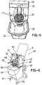
- FIGS 3, 4 and 5 show different views of a second embodiment of the invention, referred, in general, as 20, which is constituted starting from a bucket 22 made of any material, situated on the upper surface of a support and translation part 23 fitted with free turning wheels 24, the bucket 22 having a handle or holder - 26, knurled at its center position to make easy its grasping and adherence to the user's hand.
- a second embodiment of the invention referred, in general, as 20, which is constituted starting from a bucket 22 made of any material, situated on the upper surface of a support and translation part 23 fitted with free turning wheels 24, the bucket 22 having a handle or holder - 26, knurled at its center position to make easy its grasping and adherence to the user's hand.
- a squeezing head 25 is mounted on the bucket 22 by conventional means, which is formed by a casing housing an electric motor, a shaft, gears, a battery and a relay (not shown in the figure, as they are conventional elements, coupled one other in order to achieve the purpose of driving squeezing vanes), the function of the motor being to receive the battery or accumulator current after an external switch 29, located within a notch 28 having a semicircular arc shape, vertically situated, is pressed by the handle or holder of the mop with a ligtht pressure, a relay acting once the switch 29 has been operated, giving the appropiate orders to the inside of the squeezing head with the purpose of causing the motor to act, starting to turn, and setting in motion a shaft acting on the squeezing arms or vanes 27, exerting a pressure on the mop or scrubber located within the basket acting as a filter 30, squeezing the content of water from the mop, this water passing inside the bucket 22, the dirtiness potentially
- the shaft acting in cooperation with the gears due to the fact that it is fitted with a notch acting as end-of-stroke, stops the motion of the squeezing arms or vanes 27, and the presioning operation on the mop by means of the squeezing vanes or arms 27 can be repeated upon acting again on the switch 29, turning the motor fed by an electric current obtained from the battery or accumulator, and commencing again the cycle.
- the bucket 22 has, on its upper edge, a diametrical trimming stiffing it in order to allow a coupling of the squeezing head 25.
- the squeezing head 25 has, in its external portion, exactly on one of its sides, a light pilot 34, showing every moment that the battery or accumulator incorporated inside the squeezing head 25 is being charged by means of an electric current intake configurated as a flexible cable having, at one of its ends, a female pin incorporated in the intake 35, while the other end of the cable has a male pin connected to a conventional electric power intake.
- the squeezing head 25 has a pilot 31 to be lighted on when the lighting switch 32 has been actuated, this switch allowing - that, by operating the grasping element or handle which carries the mop, exactly by the pressure exerted by the user and through the stick on the switch 29, the arms 27 act, squeezing the water carried by the mop and dropping within the bucket 22 thru the bascket or filter 30.
- the squeezing head 25 can be removed from its operational housing, and once the bucket 22 has been duly cleaned up, the squeezing head 25 can be housed within the bucket 22, occupying a minimal space.
- Figures 6 and 7 show a third embodiment of the invention, which has been referenced in a general way with 40, and being constituted starting from a casing or frame 42, on which all the acting mechanisms of the object of the invention are placed, and this assembly of frame or similar 42 being placed on a conventional bucket 43 by using anchoring links 59 located on the back - side thereof, and having lateral projections emerging from steps 60 formed or located at the lower part of the main part.
- the frame or casing 42 is located on a bucket 43, and this, in turn, is placed on a transport carriage 44 fitted with appropiate wheels 45, and it can optionally carry a basket 47 to contain auxiliary elements for cleaning purposes, such as a spare mop, the basket being installed on the vertical arms of handle 46, which facilitates the motion of the assembly composed of a bucket carrying the squeezer on its upper mouth and fixed to one of its - side branches.
- the squeezer has a retaining link for the mop holder 48, fixed to a front area, presenting a center recesss on the upper portion 50, fitted with a switch thru which and with the assistance of the mop o scrubber stick, a light pressure is exerted on said switch,setting automatically in motion the motors in a sense or other, according to the turning of the current obtained from the battery and being determined by a relay driven by said switch 50, and thanks to the cooperation of an end-of-stroke switch (non referenced).
- the motor When the operating switch 50 is enabled, that is to say, when it is subject to the tool and handle or holder of the mop or scrubber pressure, the motor will run in the desired sense, moving the gear assemblies and these latter, in turn, will move the arms 51 and 52, performing the pressing or squeezing operation, so achieving that the arms 51 and 52, when approaching one other, squeeze the mop or scrubber, the water falling towards the lower zone, - passing thru a grating 49, which collects the refuse of the materials caught by the mop, and the water, now practically clean, pass into the bucket 43 on which the assemby is installed.
- the invention relais on a lighting - pilot 54, a main switch 55 and a rapid access protection relay - 56, located on one of the back sides of frame 42, while on the opposite side, a charge indicator pilot 57 is installed, which acts as an indicator for the electric power fed by the battery (not - shown) through a conventional cable 53 plugged in a plug located at the squeezer, and having the other end connected to a conventional socket linked to the electric network.
- the side vanes of support 60 located at the lower part of the frame or casing 42, can optionally have two emerging stubs 58 to be duly engaged on the side walls of bucket 43, exactly on the upper inner zone thereof.
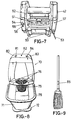
- a fourth embodiment of the invention is illustrated, with general reference 70, which is constituted, as in previous - cases, starting from a bucket 71 made of an appropiate material having a plantar rectangular shape and having all its vertices rounded, presenting, at its upper portion, a perimetral oversized edge acting as a reinforcement link of the own bucket 71, allowing-to fix on same a body 74, inside which all acting elements of the - object of the invention are incorporated.
- the bucket 71 has a handle or holder 75 and it is situated on a platform 72 provided with free turning wheels 73 to make easy its transportation and avoid the user to carry out efforts during the cleaning operations.
- a body containing mechanical and electric elements 74 is installed, having a basket 79 presenting a plurality of perforations in order to allow to pass the water taken out from the mop or scrubber, the main body 79 having a reverse truncated cone shape and with inner vanes 76 acting to perform the mop or scrubber squeezing, these vanes 76 being moved by the motor located in the frame or casing shaping the body 74.
- a pilot light 80 On the upper portion of the main body 74, frame or casing, a pilot light 80. a main switch 81, a fuse holder 82, an indicator 83 are arranged, the function of said indicator 83 being to inform the user about the necessity of recharge the battery located inside, by engaging a feeder in the base of socket 84.
- the automatic mop device by means of the vanes 76 emerging from the inner walls of basket 79, squeezes the fringes - emerging from the mop stick (shown in Fig. 9 with no reference), the vanes 76 exerting an adequate pressure to attain a full squeezing of same.
Landscapes
- Cleaning Implements For Floors, Carpets, Furniture, Walls, And The Like (AREA)
- Seal Device For Vehicle (AREA)
- Preliminary Treatment Of Fibers (AREA)
Claims (5)
- Eine automatische Wischmop-Vorrichtung zur Bodenreinigung, einbegriffen einen merklich verlängerten und zylindrischen Griff oder Stiel aus beliebigem Material, besagter Griff oder Stiel, an einem seiner Extreme mit einem Trägerstück für eine Quaste aus Textilmaterial versehen und geeignet Flüssigkeiten zu absorbieren, einen Kübel (4) oder ähnliches Gefäss beliebigen Materials oder beliebiger Form, ausgestattet mit einer Plattform (2), die als Bodenplatte dient, und am unteren Teil versehen mit sich frei drehenden Rädern (3), die das Gleiten der Vorrichtung erlauben, die Plattform (2) verfügt an einer Seitenwand über ein Gehäuse (15), in dessem Inneren ein Elektromotor untergebracht wird, dadurch charackerisiert, dass der Elektromotor über einen Endausschalter verfügt, eine 12 Volt-Batterie zur Speisung des Motors und der relativen Anschlüsse, das Gehäuse (15) hat an einer seiner Seitenwände einen ersten Arm, zusammengesetzt aus zwei Abschnitten (7-7'), an einer Stelle gegliedert (16), der erste Arm, versehen mit einem Griff oder Henkel (13), einem Gleitrohr (8), dessen Funktion darin besteht, beide Armabschnitte (7-7') zu fixieren, ein zweiter Arm (5), entspringt dem zentralen Bereich des Gehäuses (15), der am mittleren unteren Teil einen zusätzlichen Auswringarm besitzt, der in das Innere des Ablauffbereichs des über der Plattform (2) gelegenen Kübels (4) angeschlossen wird, der zweite Arm (5), an einem seiner Extreme über einen Schalter (6) verfügend, der unter Mitwirkung des Stiels oder Griffs des Wischmops tätig wird; insbesondere ein Kübel (22), vesteift durch eine Verdickung, auf dem mit heckömmlichen Mitteln ein Auswringkopf (25) befestigt wird, in dessem Innenren sich aktivierende Elemente befinden, die sich durch vorherigen Druck des Mopstiels auf einen Schalter (29) in Gang setzen, der Schalter (29), angebracht an der Stirnseite des Gehäuses, gebildet aus dem Auswringkopf, in dessem mittleren Bereich sich eine Kerbe (28) befindet, wo der Schalter (29) angebracht ist, der auf ein Relais wirkt und anschliessend auf den restlichen Mechanismus, bis der Endschalter tätig wird, der die äusseren Arme oder Flügel (27) zum Inneren eines Körbchens (30) hin mobilisieren, auf dem vorher der Wischmop plaziert wurde; insbesondere ein Gehäuse oder Auswringkopf (42), der am oberen Teil eines herkömmlichen Kübels (43) befestigt wird, welcher über einen Verankerungskranz (19) verfügt, angebracht am hinteren und unteren Teil desselben und einigen inneren Ansätzen (6), insbesondere versehen mit hervorragenden Zapfen (58) zur Befestigung an den inneren Seitenwänden des Trägerkübels (43), das Gehäuse oder der Auswringkopf (42) zählt mit einen Gitter (49), das wie ein Filter wirkt, im Inneren des Gehäuses oder Ausinringkopfes (42) befinden sich zwei Motore und zwei Zahneingriff-Einheiten, seitlich angebracht und von zwei Batterien betätigt, verfügt es über eine Kontrollampe (57) zur Anzeige der Ladetätigkeit der Batterien, falls erforderlich, das mehrgelochte Körbchen, das als Filter wirkt und wie ein Körbchen (79) gestaltet ist, verfügt insbesondere über zwei Flügel (76), die dem Inneren der Seitenwände entspringen, und den Mopstiel, ausgestattet mit einem Magnet (85), der bei der Annäherung an den Stirnbereich des oberen Gehäuses einen Mikroschalter tätigt, der die Flügel (76) während einer durch einen Zeitschalter geregelten vorbestimmten Zeit mobilisiert, dieser Zeitschalter befindet sich im Inneren des Gehäuses oder Auswringkopfes (42).
- Verbesserter automatischer Wischmop zur Bodenreinigung, gemäss des ersten Anspruchs, dadurch charakterisiert, dass an der äusseren Vorderseite des Gehäuses (15) eine Basis (10) für die Anbringung des Batterieladers angebracht wurde, versehen mit einem Hauptschalter (14) und einem Sicherungshalter von 15 Ampere (12), wobei das Gehäuse (15) auf der Basis (2) , durch einen Kübel gebildet, mit Hilfe von Schrauben (11) befestigt bleibt.
- Verbesserter automatischer Wischmop zur Bodenreinigung, gemäss des ersten und zweiten Anspruchs, dadurch charakterisiert, dass der Motor in seiner Bewegung während einer vorbestimmten Zeit begrenzt ist, um das Auswringen der Quaste durchzuführen, während die Ruhezeit durch einen Schalter mit Endausschalter festgelegt ist, der die Polarität des Motors umkehrt und seine Drehrichtung ändert; der Endausschalter, durch eine Kerbe gestaltet, die sich öffnet und dadurch die Polarität des Motors umkehrt und damit den Arm in seine Ruhestellung zurückbringt und mit Hilfe der Tätigung des Schalters (6) das Auswringmanöver wieder einsetzt..
- Verbesserter automatischer Wischmop zur Bodenreinigung, gemäss des ersten Anspruchs, dadurch charakterisiert, dass sich über einer der äusseren Vorderseiten des Auswringkopfes eine Kontrollampe (34) befindet, die die Speisung zur Aufladung der Batterie oder des Akkumulators mittels eines an das Stromnetz angeschlossenen elektrischen Kabels anzeigt, welches mit einen Hauptschalter (32) versehen ist, der eine mit einer Schutzsicherung (33)ausgestattete Kontrollampe (31) in Funktion setzt und das Ingangsetzen des Wischmops anzeigt.
- Verbesserter Wischmop zur Bodenreinigung, gemäss des ersten Anspruchs, dadurch charakterisiert, dass, im Falle des Vorhandenseins zweier Motoren, diese sich in einer oder der anderen Richtung drehen, was davon abhängig ist, aus welcher Richtung sie den Strom der Batterien erhalten, wobei diese Tätigkeit mittels eines durch einen Schalter (59) betribenen Relais bestimmt wird und der über einen Endausschalter verfügt, wobei der Schalter durch den Griff oder Stiel des Wischmops in Bewegung gesetzt wird.
Applications Claiming Priority (8)
| Application Number | Priority Date | Filing Date | Title |
|---|---|---|---|
| ES9300636U | 1993-03-11 | ||
| ES9300636U ES1024001Y (es) | 1993-03-11 | 1993-03-11 | Fregona automatica perfeccionada para la limpieza de suelos. |
| ES9302507U ES1025723Y (es) | 1993-09-21 | 1993-09-21 | Fregona automatica perfeccionada. |
| ES9302507U | 1993-09-21 | ||
| ES9302508U | 1993-09-21 | ||
| ES9302508U ES1025724Y (es) | 1993-09-21 | 1993-09-21 | Escurridor autonomo y autonomico de mopas y fregonas. |
| ES9303452U | 1993-12-27 | ||
| ES9303452U ES1026770Y (es) | 1993-12-27 | 1993-12-27 | Fregona automatica perfeccionada. |
Publications (2)
| Publication Number | Publication Date |
|---|---|
| EP0614644A1 EP0614644A1 (de) | 1994-09-14 |
| EP0614644B1 true EP0614644B1 (de) | 1997-09-10 |
Family
ID=27443910
Family Applications (1)
| Application Number | Title | Priority Date | Filing Date |
|---|---|---|---|
| EP94500047A Expired - Lifetime EP0614644B1 (de) | 1993-03-11 | 1994-03-10 | Automatisches Mopgerät |
Country Status (3)
| Country | Link |
|---|---|
| EP (1) | EP0614644B1 (de) |
| AT (1) | ATE157849T1 (de) |
| DE (1) | DE69405428T2 (de) |
Cited By (1)
| Publication number | Priority date | Publication date | Assignee | Title |
|---|---|---|---|---|
| EP4602997A1 (de) * | 2024-02-14 | 2025-08-20 | Desarrollos Vanguardistas, S.L. | Stützplattform für moppeimer |
Families Citing this family (6)
| Publication number | Priority date | Publication date | Assignee | Title |
|---|---|---|---|---|
| EP0797948B1 (de) * | 1996-03-27 | 2000-08-23 | Jens Diehl | Vorrichtung zum Reinigen einer einen Schwamm aufweisenden Schwammscheibe |
| US6065175A (en) * | 1998-08-13 | 2000-05-23 | Tejerina; Silvia Reyero | Flooring mopping system |
| ES2246620B2 (es) * | 2003-01-16 | 2006-12-16 | Sprimsol Limpiezas, S.L. | Escurridor automatico a rodillos de mopas y similares. |
| CN108814485B (zh) * | 2018-08-06 | 2023-11-10 | 浙江美添乐家居用品股份有限公司 | 一种脱水清洗一体式拖把桶 |
| CN113576363B (zh) * | 2020-10-29 | 2022-06-14 | 云和县奥丽多图文设计工作室 | 一种可以自动去除拖把上杂物的洗拖把桶 |
| NL1044299B1 (nl) * | 2022-04-12 | 2023-11-03 | Reborg Solutions B V | Inrichting en werkwijze voor het uitknijpen van een natte doek |
Family Cites Families (7)
| Publication number | Priority date | Publication date | Assignee | Title |
|---|---|---|---|---|
| DE2227554A1 (de) * | 1972-06-07 | 1973-12-20 | Gustav Huebner | Reinigungsautomat fuer tuecher und mops, insbesondere schrubb- und trockenwischtuecher sowie schrubb- und trockenwischmops und reinigungstuecher |
| US3987513A (en) * | 1975-12-18 | 1976-10-26 | Gonzales Charles M | Mop wringer |
| US4344201A (en) * | 1980-12-03 | 1982-08-17 | Trisolini George S | Cleaning apparatus |
| US4722113A (en) * | 1985-12-02 | 1988-02-02 | Olsson Arvid T | Mop handle stabilizer |
| DE4023219A1 (de) * | 1990-07-21 | 1992-01-23 | Dieter Sacks | Auspressgeraet fuer reinigungstuecher u. dgl. |
| FR2672791B1 (fr) * | 1991-02-14 | 1994-12-23 | Maxnet | Dispositif d'essorage pour tete de balai. |
| JPH0724645B2 (ja) * | 1991-05-31 | 1995-03-22 | 修三 小野寺 | モップ洗浄用自動吸水装置 |
-
1994
- 1994-03-10 EP EP94500047A patent/EP0614644B1/de not_active Expired - Lifetime
- 1994-03-10 AT AT94500047T patent/ATE157849T1/de not_active IP Right Cessation
- 1994-03-10 DE DE69405428T patent/DE69405428T2/de not_active Expired - Lifetime
Cited By (1)
| Publication number | Priority date | Publication date | Assignee | Title |
|---|---|---|---|---|
| EP4602997A1 (de) * | 2024-02-14 | 2025-08-20 | Desarrollos Vanguardistas, S.L. | Stützplattform für moppeimer |
Also Published As
| Publication number | Publication date |
|---|---|
| DE69405428D1 (de) | 1997-10-16 |
| EP0614644A1 (de) | 1994-09-14 |
| DE69405428T2 (de) | 1998-04-16 |
| ATE157849T1 (de) | 1997-09-15 |
Similar Documents
| Publication | Publication Date | Title |
|---|---|---|
| US4875246A (en) | Surface treating device | |
| US12213633B2 (en) | Surface cleaning apparatus and tray | |
| US7174603B2 (en) | Multi-purpose position sensitive floor cleaning device | |
| US7434292B2 (en) | Automatic roller wringer | |
| EP0614644B1 (de) | Automatisches Mopgerät | |
| EP2568863B1 (de) | Reinigungsmethode von mop-material | |
| CN203000816U (zh) | 电动扫地机 | |
| WO2015189563A1 (en) | Apparatus for cleaning a floor surface | |
| KR102110385B1 (ko) | 천연 펄프를 이용한 다용도 물걸레 | |
| MX2007014947A (es) | Limpiador de telas. | |
| CN211511662U (zh) | 一种擦地机充电坞 | |
| US4959628A (en) | Rotating electric switch actuated by fixed magnetic means, usable for a surface cleaning device | |
| CN216495125U (zh) | 清洁设备 | |
| KR102357919B1 (ko) | 핸드헬드 진공 청소기 | |
| CN213321876U (zh) | 一种厨余垃圾干湿分离设备 | |
| KR200458082Y1 (ko) | 걸레포 착탈형 물걸레 청소기 및 이를 수용하는 홀더 | |
| CN222751620U (zh) | 一种多功能手持式自动鞋衣刷 | |
| CN211155587U (zh) | 一种可蓄水的旋转拖把 | |
| WO2019026882A1 (ja) | 電気掃除機 | |
| JP3106567U (ja) | プラスチック類圧縮器 | |
| JPH08140920A (ja) | 電動ハンドクリーナー | |
| JPH0824187A (ja) | 充交両用電気掃除機 | |
| KR20070117828A (ko) | 몹걸레의 자동 롤러 링거 | |
| CN112515608A (zh) | 一种利用静电吸附的衣物除尘刷 | |
| CN110558912A (zh) | 改进的拖把清洗器 |
Legal Events
| Date | Code | Title | Description |
|---|---|---|---|
| PUAI | Public reference made under article 153(3) epc to a published international application that has entered the european phase |
Free format text: ORIGINAL CODE: 0009012 |
|
| AK | Designated contracting states |
Kind code of ref document: A1 Designated state(s): AT BE CH DE FR GB GR IE IT LI NL PT SE |
|
| 17P | Request for examination filed |
Effective date: 19950206 |
|
| 17Q | First examination report despatched |
Effective date: 19960326 |
|
| GRAG | Despatch of communication of intention to grant |
Free format text: ORIGINAL CODE: EPIDOS AGRA |
|
| GRAH | Despatch of communication of intention to grant a patent |
Free format text: ORIGINAL CODE: EPIDOS IGRA |
|
| GRAH | Despatch of communication of intention to grant a patent |
Free format text: ORIGINAL CODE: EPIDOS IGRA |
|
| GRAA | (expected) grant |
Free format text: ORIGINAL CODE: 0009210 |
|
| AK | Designated contracting states |
Kind code of ref document: B1 Designated state(s): AT BE CH DE FR GB GR IE IT LI NL PT SE |
|
| PG25 | Lapsed in a contracting state [announced via postgrant information from national office to epo] |
Ref country code: LI Effective date: 19970910 Ref country code: GR Free format text: LAPSE BECAUSE OF FAILURE TO SUBMIT A TRANSLATION OF THE DESCRIPTION OR TO PAY THE FEE WITHIN THE PRESCRIBED TIME-LIMIT Effective date: 19970910 Ref country code: CH Effective date: 19970910 Ref country code: AT Effective date: 19970910 |
|
| REF | Corresponds to: |
Ref document number: 157849 Country of ref document: AT Date of ref document: 19970915 Kind code of ref document: T |
|
| REG | Reference to a national code |
Ref country code: CH Ref legal event code: EP |
|
| REF | Corresponds to: |
Ref document number: 69405428 Country of ref document: DE Date of ref document: 19971016 |
|
| ITF | It: translation for a ep patent filed | ||
| ET | Fr: translation filed | ||
| REG | Reference to a national code |
Ref country code: IE Ref legal event code: FG4D Free format text: 76371 |
|
| REG | Reference to a national code |
Ref country code: PT Ref legal event code: SC4A Free format text: AVAILABILITY OF NATIONAL TRANSLATION Effective date: 19971203 |
|
| REG | Reference to a national code |
Ref country code: CH Ref legal event code: PL |
|
| PLBE | No opposition filed within time limit |
Free format text: ORIGINAL CODE: 0009261 |
|
| STAA | Information on the status of an ep patent application or granted ep patent |
Free format text: STATUS: NO OPPOSITION FILED WITHIN TIME LIMIT |
|
| 26N | No opposition filed | ||
| REG | Reference to a national code |
Ref country code: GB Ref legal event code: IF02 |
|
| PGFP | Annual fee paid to national office [announced via postgrant information from national office to epo] |
Ref country code: IE Payment date: 20100330 Year of fee payment: 17 |
|
| PGFP | Annual fee paid to national office [announced via postgrant information from national office to epo] |
Ref country code: FR Payment date: 20100303 Year of fee payment: 17 |
|
| PGFP | Annual fee paid to national office [announced via postgrant information from national office to epo] |
Ref country code: GB Payment date: 20100323 Year of fee payment: 17 Ref country code: BE Payment date: 20100216 Year of fee payment: 17 |
|
| PGFP | Annual fee paid to national office [announced via postgrant information from national office to epo] |
Ref country code: NL Payment date: 20100223 Year of fee payment: 17 Ref country code: DE Payment date: 20100219 Year of fee payment: 17 |
|
| PGFP | Annual fee paid to national office [announced via postgrant information from national office to epo] |
Ref country code: SE Payment date: 20100305 Year of fee payment: 17 |
|
| BERE | Be: lapsed |
Owner name: *RAMIREZ MORENO MARIA DEL CARMEN Effective date: 20110331 |
|
| REG | Reference to a national code |
Ref country code: NL Ref legal event code: V1 Effective date: 20111001 |
|
| REG | Reference to a national code |
Ref country code: SE Ref legal event code: EUG |
|
| GBPC | Gb: european patent ceased through non-payment of renewal fee |
Effective date: 20110310 |
|
| REG | Reference to a national code |
Ref country code: FR Ref legal event code: ST Effective date: 20111130 |
|
| PG25 | Lapsed in a contracting state [announced via postgrant information from national office to epo] |
Ref country code: BE Free format text: LAPSE BECAUSE OF NON-PAYMENT OF DUE FEES Effective date: 20110331 |
|
| REG | Reference to a national code |
Ref country code: IE Ref legal event code: MM4A |
|
| PG25 | Lapsed in a contracting state [announced via postgrant information from national office to epo] |
Ref country code: NL Free format text: LAPSE BECAUSE OF NON-PAYMENT OF DUE FEES Effective date: 20111001 Ref country code: IE Free format text: LAPSE BECAUSE OF NON-PAYMENT OF DUE FEES Effective date: 20110310 Ref country code: FR Free format text: LAPSE BECAUSE OF NON-PAYMENT OF DUE FEES Effective date: 20110331 Ref country code: DE Free format text: LAPSE BECAUSE OF NON-PAYMENT OF DUE FEES Effective date: 20111001 |
|
| REG | Reference to a national code |
Ref country code: DE Ref legal event code: R119 Ref document number: 69405428 Country of ref document: DE Effective date: 20111001 |
|
| PG25 | Lapsed in a contracting state [announced via postgrant information from national office to epo] |
Ref country code: GB Free format text: LAPSE BECAUSE OF NON-PAYMENT OF DUE FEES Effective date: 20110310 |
|
| PGFP | Annual fee paid to national office [announced via postgrant information from national office to epo] |
Ref country code: IT Payment date: 20120321 Year of fee payment: 19 |
|
| PG25 | Lapsed in a contracting state [announced via postgrant information from national office to epo] |
Ref country code: SE Free format text: LAPSE BECAUSE OF NON-PAYMENT OF DUE FEES Effective date: 20110311 |
|
| PGFP | Annual fee paid to national office [announced via postgrant information from national office to epo] |
Ref country code: PT Payment date: 20130225 Year of fee payment: 20 |
|
| REG | Reference to a national code |
Ref country code: PT Ref legal event code: MM4A Free format text: MAXIMUM VALIDITY LIMIT REACHED Effective date: 20140310 |
|
| PG25 | Lapsed in a contracting state [announced via postgrant information from national office to epo] |
Ref country code: PT Free format text: LAPSE BECAUSE OF EXPIRATION OF PROTECTION Effective date: 20140318 |